ONCWPRRange Enhancing Repeater
DynaQuip Controls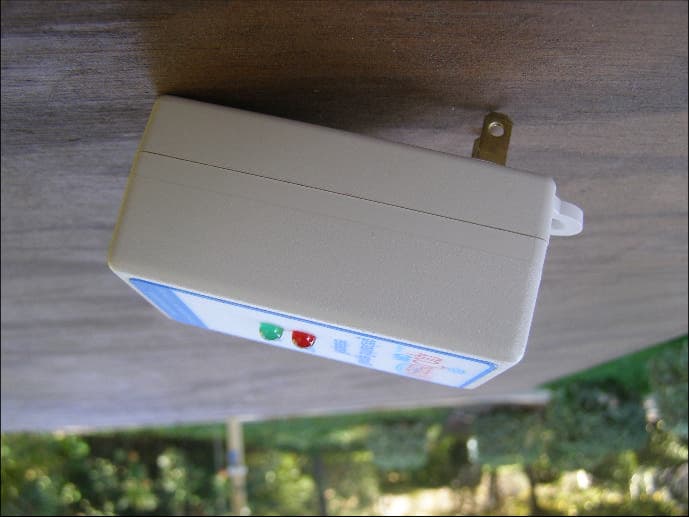
Click to zoom
Application Details
- Equipment Class
- DSR - Part 15 Remote Control/Security Device Transceiver
- Date of Grant
- Feb 21, 2010
- Application Purpose
- Original Equipment
- Date of Application
- Feb 21, 2010
- Equipment Note
- Range Enhancing Repeater
- Frequency Range
- 433.92000000 - 433.92000000
- Company
- DynaQuip Controls
- Country
- United States
Documents & Files
Document Text
Text extracted from the exhibit documents filed with the FCC. Open a document above to read the original.
Users Manual
Owner’s Manual / Installation Guide www.watercop.com 800-545-3636 System Description The WaterCop ® PRO System is designed to detect leaks in your plumbing system at predetermined locations, and automatically shut off the water supply to help effectively reduce the chances of major water damage associated with a leak. System Components Brass Valve: Full Port, brass, 125psi cold water, designed for placement on incoming water main. WaterCop Actuator: NEMA 4 (weatherproof) Polycarbonate enclosure for indoor/outdoor installation, AC/DC power converter with 20’ cord included, Liquid crystal display with back light for sensor/trouble status, ambient temperature 35°F to 105°F, for cold water applications. Manual override, Local open/close water control. Flood Sensor: Power using 2 AA Alkaline Batteries or optional AC/DC power converter (sold separately). Batteries will provide back up power upon loss of electricity. Wireless sensors are addressable and supervised for conditions such as water detection, power lost, sensor short/open and low battery. Ten foot sensor cord allows optimal sensor placement. Flood sensors can support one or two sensor wires. Each WaterCop ® PRO actuator valve can support up to 45 wireless sensors. Range Enhancing Repeater: Enhances transmission range of wireless sensors. Plugs into any standard wall outlet. Receives and re-transmits sensor signals from outlying sensors to the WaterCop ® PRO actuator. Monitoring Station-Standard: LCD display with back light provides instant feedback of sensor alarm and trouble conditions as well as open/close status of water supply. Local push button water controls for instant on/ off of water supply. Audible alarm sounds when any sensor detects flooding. Internal mounting bracket mounts to standard wall boxes for aesthetics and cord management. AC/DC power converter with 20’ cord included. Monitoring Station-Hardwired (pictured above): Accommodates up to 8 zones for WPSC hardwired flood sensors (sold separately). NEED NEW PHOTO use an extension cord. The shut-off valve must be installed • In the main water line; • In place of or just downstream from the main water shut-off valve; • Where it is accessible • Where the case is protected from use as a step or from other excessive loads. Local electrical and plumbing codes should be consulted to ensure that the installation is in complete compliance. (See Installation section for details.) Placement of Flood Sensors Each WaterCop ® PRO can support an unlimited number of flood sensors. Additional sensors may be added at any time. A sensor consists of a transmitter and a sensor probe (a small disc at the end of the wire, with two short gold prongs protruding from one side). Flood sensors should be placed in locations where leaks are most likely to occur. Suggested Locations • Washing Machines • Toilets • Dishwashers • Icemakers/Refrigerators • Kitchen Sinks • Automatic Humidifiers • Bathroom Sinks • Water Heaters • Pipes that are prone to freezing (Freeze sensors are also available) The transmitter in the flood sensors and the receiver in the WaterCop ® PRO communicate by radio frequency. The smaller the distance between them, the stronger the signal will be. Transmission distance is somewhat dependent upon the building layout and type of construction. The transmitter (attached to the sensor) must be kept dry. It is NOT splash proof. Sensors should never be placed outdoors. The sensor probe detects the water from a leak and is completely waterproof. Sensor probes should be placed on the floor or in areas where water would tend to accumulate rapidly in common leak or overflow situations. Make sure that any water from a leak will drain toward the sensor probe, not away from it. Avoid high traffic areas where the cord or sensor could be stepped on or kicked and where children or pets may disturb it. The sensor probe should be placed FLAT on the floor so water can be detected as soon as it begins to accumulate. The sensor probe may be secured to the floor with screws. To avoid damage to transmitters and to provide for the strongest signal possible, the transmitter portion of the flood sensor should be mounted in a convenient location (on the wall, in a cabinet, closet, etc.) two to three feet above the floor (see illustration). (See Installation section for details on sensor installation.) Hard Wired Sensors: Ten foot white cord with single sensor. PRO sensors are easily secured to floor using mounting holes. Sensors provide the same feedback to monitoring station as the wireless WaterCop ® PRO sensors. Use hardwired censors for convenience or if conditions prevent wireless communication. Sensors sold individually and can be wired with up to 200 feet of 22/24 AWG 2-conductor cord (not included). General Safety Information Warning Do not apply electrical power to the unit unless the unit is fully assembled. Failure to do so could result in personal injury and/or damage to the unit. Warning Disconnect power source before working on or servicing the unit. Failure to do so could result in personal injury. Caution It is strongly recommended that eye protection be worn while servicing the system. Failure to do so could result in personal injury. How the System Works Flood sensors constantly monitor their selected areas for accumulating moisture. When a leak is detected, a sensor will send a radio frequency signal to the WaterCop ® PRO unit instructing it to shut off the water supply to the home. The WaterCop ® PRO valve will remain closed until it is manually reset. The flood sensors are a battery powered device enabling it to be located anywhere a leak is likely to occur, or where water might cause damage. The WaterCop ® PRO requires household electrical power (common 115 VAC, grounded outlet) and will not operate during a power outage. Selection of WaterCop ® PRO Installation Sites The WaterCop ® PRO valve should be installed in the main water line just downstream from the main shut- off valve in y…
Text truncated - open the document above for the full version.
Attestation Statements
Telephone: (636) 6: Sales Fax: (636) 6: Operations Fax: (636) 6: J Cont www.dynac o ris Industrial Park St. Clair, MO 63077 November 9, 2009 CETCB 114 Olinda Drive Brea, CA 92823 Gentlemen: This is a letter of authorization to accept Compatible Electronics, .Inc., specifically including the employees of Compatible Electronics, as an Agent for DynaQuip Controls Inc. 10 Harris Industrial Park, St. Clair, MO 63077, for a period of one year, to sign applications before the Commission on our behalf, to make representations to you on our behalf, and to receive and exchange data between our company and the Commission in connection with certification of the following DynaQuip Controls product: Emergency Water Shut-Off System USing Transmitters and Receivers under FCC Docket Number 20780 and General Docket Number 80-284 pursuant to Part 15 of FCC Rules and Regulations. Please also accept this letter as an attestation that neither DynaQuip Controls nor any of its officers, directors, or persons holding 5% or more of the outstanding stock or shares, voting or non-voting, have been denied federal benefits under section 5301 of the Anti Drug-Abuse act of 1988,21 U.S.C. 853(a). In addition, DynaQuip Controls will notify the Federal Communications Commission if, at any time, the situation changes causing DynaQuip Controls to be denied federal benefits. If you have any further questions or need additional information, please feel free to give me a call at 636-629-3700. \Q~-----L ~~neyBryan Jr. I r-.... · President/CEO
Attestation Statements
DBXffi J. Rodney Bryan Jr. President/CtrO Telephone: (636l' 629'3700 Soles Fox: (636) 629-5528 Operotions Fox: (636) 629-7724 www.dynoquip.com I0 Horris lndustriol Pork St. Cloir, MO 63077 January 12,2010 Compatible Electronics TCB 114 Olinda Drive Brea, CA 92823 Subject: TCB application submittal Gentlemen, We, DynaQuip Controls Inc., would like to declare that the application being submitted for the device with FCC ID: ONCWPR has not been submitted to another TCB or FCC for certification. If you have any questions, please do not hesitate to contact us at 636-629-3700. Sincerely, k. ',*.- l:-yh
Cover Letter(s)
l Telephone: (636) 6 DynaQuip Sales Fax: (636) 6 Operations Fax: (636) 6 Controls® www.dyna larris Industrial Park St. Clair, MO 63077 November 9, 2009 Compatible Electronics TCB 114 Olinda Drive Brea, California 92823 Subject: Request for withholding from public disclosure the schematics, block diagrams, and operational description pursuant to an application for certification Gentlemen: We, DynaQuip Controls Inc ., would like to request that all schematics, block diagrams, and operational descriptions submitted with the application for certification be withheld from public disclosure as per Section 0.459 of FCC Rules. . This request is made under the provisions of Section 0.457 (d) of the Commission' s Rules, and Section 552 (b)(4) ofthe Freedom ofInformation Act. These sections authorize the withholding from public inspection, those materials which would be privileged as a matter of law if retained by the person submitting them, and materials which would not customarily be released to the public by that person. If you have any questions, please do not hesitate to contact us at 636-629-3700. Sincerely, ~~-.~. President/CEO
Cover Letter(s)
1 Scott McCutchan From: Scott McCutchan [[email protected]] Sent: Tuesday, February 16, 2010 11:46 PM To: [email protected]; [email protected]; [email protected] Subject: FCC ID: ONCWPR Mr. Fujimoto: In order for processing of this certification application (FCC ID: ONCWPR) to continue, the following issue(s) will have to be addressed: 1) Please provide the FCC ID(s) of the transmitter(s) with which the repeater is intended to operate. 2) Please provide the FCC ID of the transmitter used for the interoperability test. 3) Please describe the methodology employed for determining the repeater continues to comply with the applicable requirements with maximum input levels. 4) Please indicate whether the repeater only transmits when it demodulates and decodes (validates) an incoming signal from the specific transmitter(s) with which it authorized to operate. The item(s) indicated above must be submitted before processing can continue on the above referenced application. Failure to provide the requested information within 60 days of the original e-mail date may result in application dismissal. and forfeiture of the filing fee. Also, please note that partial responses increase processin g time and should not be submitted. Please upload responses and/or exhibits to the electronic filing website. Your correspondence number is ONCWPR. Best regards, Scott McCutchan Operations Manager Compatible Electronics TCB ------------------------------------------------ "Follow our EMC and Regulatory Compliance blog at http://feeds.feedburner.com/EMCNews " 2004/108/EC - Notified Body #: 1925 Conformity Assessment Body #: US0066, US0135, US0145 A U.S. Telecommunications Certification Body (TCB) NVLAP Lab Codes: 200063-0, 200527-0 and 200528-0 If you received this in error, please let us know and delete the file. Compatible Electronics, Inc. advises all recipients to virus scan all emails, thank you for the opportunity to assist with your compliance needs!
Cover Letter(s)
Correspondence by Project Project Number: 1553034481 Correspondence Number Memo ONCWPR 1. The FCC ID of the Transmitter that the repeater is intended to operate is FCC ID: ONCWPFS 2. The transmitter used for the interoperability test is FCC ID: ONCWPFS 3. The test report has been revised to describe the method employed for determining the repeater continues to comply with the applicable requirements with maximum input levels. 4. The first paragraph of the last page of the Theory of Operation addresses if the repeater only transmits when it demodulates and decodes (validates) an incoming signal from the specific transmitter with which it is authorized to operate.
ID Label/Location Info
ECO INTERNAL CORNER RADII .010 MAX. R. UNLESS OTHERWISE SPECIFIED: ALL MACHINED SURFACES TO HAVE 125 RMS FINISH BREAK ALL CORNERS .005/.010 X 45° UNLESS OTHERWISE SPECIFIED ALL DIMENSIONS AREIN INCHES. TOLERANCES ARE: ANGLES +/- 2 DEG.FRACTIONS +/-.015 .X +/-.100.XX +/-.015.XXX +/-.005 FILE NO. DATE ECO LET THIS PRINT IS THE PROPERTY OF DYNAQUIP CONTROLS AND SHALL NOTBE COPIED, REPRODUCED, LOANED, OR DISPOSED OF DIRECTLY OR IN-DIRECTLY, NOR USED FOR ANY PURPOSE OTHER THAN THAT FOR WHICHIT IS SPECIFICALLY FURNISHED EXCEPT BY WRITTEN PERMISSION OFDYNAQUIP CONTROLS. NO DO NOTSCALE TITLE DR CH'KD ENGR DATE DATE DATE MATERIAL FINISH DATE LET ONCWPRLABEL including interference that may cause undesired operation. MJP 11-13-09 FCC LABEL PLACEMENTWPR FCC ID: ONCWPRThis device complies with part 15 of the FCC Rules.Operation is subject to the following two conditions:(1) This device may not cause harmful interference and(2) This device must accept any interference received, Label 1" x 2"
Test Report
Report Number: B91103D2 FCC Part 15 Subpart B and FCC Section 15.231 Test Report Range Enhancing Repeater Model: WPR Brea Division 114 Olinda Drive Brea, CA 92823 (714) 579-0500 Ajoura Division 2337 Troutdale Drive Agoura, CA 91301 (818) 597-0600 Silverado Division 19121 El Toro Road Silverado, CA 92676 (949) 589-0700 Lake Forest Division 20621 Pascal Way Lake Forest, CA 92630 (949) 587-0400 Page 1 of 17 FCC PART 15 SUBPART B and C TEST REPORT for RANGE ENHANCING REPEATER Model: WPR Prepared for DYNAQUIP CONTROLS 10 HARRIS INDUSTRIAL PARK ST. CLAIR, MISSOURI 63077 Prepared by:_____________________ KYLE FUJIMOTO Approved by:____________________ MICHAEL CHIRSTENSEN COMPATIBLE ELECTRONICS INC. 114 OLINDA DRIVE BREA, CALIFORNIA 92823 (714) 579-0500 DATE: NOVEMBER 18, 2009 REPORT APPENDICES TOTAL BODY A B C D E PAGES 17 2 2 2 13 23 59 This report shall not be reproduced except in full, without the written approval of Compatible Electronics. Report Number: B91103D2 FCC Part 15 Subpart B and FCC Section 15.231 Test Report Range Enhancing Repeater Model: WPR Brea Division 114 Olinda Drive Brea, CA 92823 (714) 579-0500 Ajoura Division 2337 Troutdale Drive Agoura, CA 91301 (818) 597-0600 Silverado Division 19121 El Toro Road Silverado, CA 92676 (949) 589-0700 Lake Forest Division 20621 Pascal Way Lake Forest, CA 92630 (949) 587-0400 Page 2 of 17 TABLE OF CONTENTS Section / Title PAGE GENERAL REPORT SUMMARY 4 SUMMARY OF TEST RESULTS 4 1. PURPOSE 5 2. ADMINISTRATIVE DATA 6 2.1 Location of Testing 6 2.2 Traceability Statement 6 2.3 Cognizant Personnel 6 2.4 Date Test Sample was Received 6 2.5 Disposition of the Test Sample 6 2.6 Abbreviations and Acronyms 6 3. APPLICABLE DOCUMENTS 7 4. DESCRIPTION OF TEST CONFIGURATION 8 4.1 Description of Test Configuration – EMI 8 4.1.1 Cable Construction and Termination 9 5. LISTS OF EUT, ACCESSORIES AND TEST EQUIPMENT 10 5.1 EUT and Accessory List 10 5.2 EMI Test Equipment 11 6. TEST SITE DESCRIPTION 12 6.1 Test Facility Description 12 6.2 EUT Mounting, Bonding and Grounding 12 6.3 Facility Environmental Characteristics 12 7. TEST PROCEDURES 13 7.1 RF Emissions 13 7.1.1 Conducted Emissions Test 13 7.1.2 Radiated Emissions (Spurious and Harmonics) Test 14 7.2 Bandwidth of the Fundamental 16 8. CONCLUSIONS 17 Report Number: B91103D2 FCC Part 15 Subpart B and FCC Section 15.231 Test Report Range Enhancing Repeater Model: WPR Brea Division 114 Olinda Drive Brea, CA 92823 (714) 579-0500 Ajoura Division 2337 Troutdale Drive Agoura, CA 91301 (818) 597-0600 Silverado Division 19121 El Toro Road Silverado, CA 92676 (949) 589-0700 Lake Forest Division 20621 Pascal Way Lake Forest, CA 92630 (949) 587-0400 Page 3 of 17 LIST OF APPENDICES APPENDIX TITLE A Laboratory Recognitions B Modifications to the EUT C Additional Models Covered Under This Report D Diagram, Charts, and Photos • Test Setup Diagram • Antenna and Amplifier Factors • Radiated Emissions Photos E Data Sheets LIST OF FIGURES FIGURE TITLE 1 Conducted Emissions Test Setup 2 Plot Map And Layout of Test Site – 3 Meters Report Number: B91103D2 FCC Part 15 Subpart B and FCC Section 15.231 Test Report Range Enhancing Repeater Model: WPR Brea Division 114 Olinda Drive Brea, CA 92823 (714) 579-0500 Ajoura Division 2337 Troutdale Drive Agoura, CA 91301 (818) 597-0600 Silverado Division 19121 El Toro Road Silverado, CA 92676 (949) 589-0700 Lake Forest Division 20621 Pascal Way Lake Forest, CA 92630 (949) 587-0400 Page 4 of 17 GENERAL REPORT SUMMARY Compatible Electronics Inc. generates this electromagnetic emission test report, which is an independent testing and consulting firm. The test report is based on testing performed by Compatible Electronics personnel according to the measurement procedures described in the test specifications given below and in the "Test Procedures" section of this report. The measurement data and conclusions appearing herein relate only to the sample tested and this report may not be reproduced without the written permission of Compatible Electronics, unless done so in full. This report must not be used to claim product endorsement by NVLAP, NIST or any other agency of the U.S. Government. Device Tested: Range Enhancing Repeater Model: WPR S/N: N/A Product Description: See Expository Statement Modifications: The EUT was not modified in order to meet the specifications. Customer: DynaQuip Controls 10 Harris Industrial Park St. Clair, Missouri 63077 Test Date(s): October 27 and 28; and November 2, 2009 Test Specifications: EMI requirements CFR Title 47, Part 15, Subpart B Test Procedure: ANSI C63.4 Test Deviations: The test procedure was not deviated from during the testing. SUMMARY OF TEST RESULTS TEST DESCRIPTION RESULTS 1 Conducted RF Emissions, 150 kHz – 30 MHz Complies with the Class B limits of CFR Title 47, Part 15, Subpart B; and CFR Title 47, Part 15, Subpart C, section 15.207 Highest reading in relation to spec limit: 45.8 dBuV @ 19.950 MHz (*Uc = 0.43 dB) 2 Radiated RF Emissions 10 kHz – 4400 MHz (Transmitter Portion) Complies with the limits of CFR Title 47, Part 15, Subpart C, sections 15.205, 15.209, and 15.231. Highest reading in relation to spec limit: 78.88 dBuV @ 433.92 MHz (*Uc = 1.76 dB) 3 Radiated RF Emissions 10 kHz – 4400 MHz (Digital and Receiver Portion) Complies with the Class B limits of CFR Title 47, Part 15, Subpart B. *U c = combined standard uncertainty Report Number: B91103D2 FCC Part 15 Subpart B and FCC Section 15.231 Test Report Range Enhancing Repeater Model: WPR Brea Division 114 Olinda Drive Brea, CA 92823 (714) 579-0500 Ajoura Division 2337 Troutdale Drive Agoura, CA 91301 (818) 597-0600 Silverado Division 19121 El Toro Road Silverado, CA 92676 (949) 589-0700 Lake Forest Division 20621 Pascal Way Lake Forest, CA 92630 (949) 587-0400 Page 5 of 17 1. PURPOSE This document is a qualification test report based on the Electromagnetic Interference (EMI) tests performed on the Range Enhancing Repeater, Model: WPR. The EMI measurements were performed according to the…
Text truncated - open the document above for the full version.
Test Report
Ref Lvl 82 dB V Ref Lvl 82 dB V RBW 100 kHz VBW 300 kHz RF Att 10 dB A IN1 Unit dB V P20 TDS 1AP SGL SWT 300 ms Center 433.8949499 MHz30 ms/ -10 0 10 20 30 40 50 60 70 -18 82 1 1 Delta 1 [T1] 1.52 dB 100.400802 ms 1 [T1] 6.94 dB V 77.715431 ms 1 [T1] 1.52 dB 100.400802 ms D1 74 dB V D2 54 dB V Date: 26.OCT.2009 07:48:26 Plot Showing Pulse Train Only Shows up once per 100 mS Cycle Ref Lvl 82 dB V Ref Lvl 82 dB V RBW 100 kHz VBW 300 kHz RF Att 10 dB A IN1 Unit dB V 1AP SGL SWT 100 ms Center 433.8949499 MHz10 ms/ P20 TDS -10 0 10 20 30 40 50 60 70 -18 82 1 1 Delta 1 [T1] 1.88 dB 63.126253 ms 1 [T1] 7.06 dB V 51.262525 ms 1 [T1] 1.88 dB 63.126253 ms D1 74 dB V D2 54 dB V Date: 26.OCT.2009 07:49:49 Pulse Train with 100 mS Scale Ref Lvl 82 dB V Ref Lvl 82 dB V RBW 100 kHz VBW 300 kHz RF Att 10 dB A SGL IN1 1AP Unit dB V P20 TDS SWT 5 ms Center 433.8949499 MHz500 s/ -10 0 10 20 30 40 50 60 70 -18 82 1 1 Delta 1 [T1] 1.69 dB 190.380762 s 1 [T1] 14.95 dB V 21.142285 ms 1 [T1] 1.69 dB 190.380762 s D1 74 dB V D2 54 dB V Date: 26.OCT.2009 08:01:52 Time of Small Pulse = 190.380762 uS Ref Lvl 82 dB V Ref Lvl 82 dB V RBW 100 kHz VBW 300 kHz RF Att 10 dB A SGL IN1 1AP Unit dB V P20 TDS SWT 5 ms Center 433.8949499 MHz500 s/ -10 0 10 20 30 40 50 60 70 -18 82 1 1 Delta 1 [T1] 1.19 dB 490.981964 s 1 [T1] 12.30 dB V 22.024048 ms 1 [T1] 1.19 dB 490.981964 s D1 74 dB V D2 54 dB V Date: 26.OCT.2009 08:03:06 Time of Medium Pulse = 490.981964 uS Ref Lvl 82 dB V Ref Lvl 82 dB V RBW 100 kHz VBW 300 kHz RF Att 10 dB A SGL IN1 1AP Unit dB V P20 TDS SWT 5 ms Center 433.8949499 MHz500 s/ -10 0 10 20 30 40 50 60 70 -18 82 11 Delta 1 [T1] 0.04 dB 661.322645 s 1 [T1] 11.41 dB V 21.242485 ms 1 [T1] 0.04 dB 661.322645 s D1 74 dB V D2 54 dB V Date: 26.OCT.2009 08:02:31 Time of Large Pulse = 661.3226545 uS Ref Lvl 82 dB V Ref Lvl 82 dB V RBW 100 kHz VBW 300 kHz RF Att 10 dB A IN1 Unit dB V 1AP SGL P20 TDS SWT 70 ms Center 433.8949499 MHz7 ms/ -10 0 10 20 30 40 50 60 70 -18 82 D1 74 dB V D2 54 dB V Date: 26.OCT.2009 07:56:45 Pulse Train with 70 mS Scale Ref Lvl 82 dB V Ref Lvl 82 dB V RBW 100 kHz VBW 300 kHz RF Att 10 dB A SGL IN1 1AP Unit dB VSWT 20 ms Center 433.8949499 MHz2 ms/ P20 TDS TRG -10 0 10 20 30 40 50 60 70 -18 82 D1 74 dB V D2 54 dB V Date: 26.OCT.2009 08:10:05 First 20 mS of the Pulse Train has 1 Large Pulse and 31 Medium Pulses Ref Lvl 82 dB V Ref Lvl 82 dB V RF Att 10 dB A Unit dB V TRG P20 TDS RBW 100 kHz VBW 300 kHz IN1 1AP SGL SWT 30 ms Center 433.8949499 MHz3 ms/ -10 0 10 20 30 40 50 60 70 -18 82 1 1 Delta 1 [T1] 54.09 dB 19.899800 ms 1 [T1] 14.27 dB V 50.040080 ms 1 [T1] 54.09 dB 19.899800 ms D1 74 dB V D2 54 dB V Date: 26.OCT.2009 08:20:27 Second 20 mS of the Pulse Train has 26 Medium Pulses and 6 Small Pulses Ref Lvl 82 dB V Ref Lvl 82 dB V RF Att 10 dB A Unit dB V TRG P20 TDS RBW 100 kHz VBW 300 kHz IN1 1AP SGL SWT 30 ms Center 433.8949499 MHz3 ms/ -10 0 10 20 30 40 50 60 70 -18 82 1 1 Delta 1 [T1] 6.23 dB 23.266533 ms 1 [T1] 13.48 dB V 43.607214 ms 1 [T1] 6.23 dB 23.266533 ms D1 74 dB V D2 54 dB V Date: 26.OCT.2009 08:31:59 Last 23.266533 mS of the Pulse Train has 29 Medium Pulses and 9 Small Pulses Total Number of Small Pulses = 15 @ 190.380762 uS = 2855.71143 uS Total Number of Medium Pulses = 86 @ 490.981964 uS = 42224.448904 uS Total Number of Large Pulses = 1 @ 661.3226545 uS = 661.3226545 uS Total on Time = 45741.4829885 uS = 45.7414829885 mS = 45.74% Duty Cycle
Test Report
HOW THE EUT MEETS THE REQUIREMENTS OF 15.31 (e) FOR THE DYNAQUIP CONTROLS RANGE ENHANCING REPEATER MODEL: WPR The fundamental was maximized on the Lab D test site using a normal test setup with the EUT connected directly to the AC public mains (115 Vac). Next, the EUT was then connected to the Staco Energy Products Variable Auto Transformer Model: 3PN1010. The Variable Auto Transformer allows the Vac input to be varied. The AC input was then dropped to 85% (97.75 Vac) and raised to 115% (132.25 Vac). The actual AC input was measured using a calibrated Fluke Multimeter Model: 87, Serial Number: 956410240, Calibration Due Date: May 28, 2010. The fundamental was then verified again to see that the amplitude did not change. Test Result: The EUT does NOT change amplitude at the fundamental when the AC input voltage is varied between 85% and 115% of the input nominal rated supply voltage.
Contact Information
Applicant
James R Bryan(President)
Technical Contact
Compatible Electronics, Inc.Kyle Fujimoto
[email protected]714-579-0500
114 Olinda Drive · Brea, California · United States
Test Firm
Compatible Electronics, Inc.Michael Christensen
Technical Specifications
| # | Rule Parts | Frequency Range | Power Output |
|---|---|---|---|
| 1 | 15.231 | 433.92 MHz - 433.92 MHz | - |
Other Applications from DynaQuip Controls
ONCWPFS
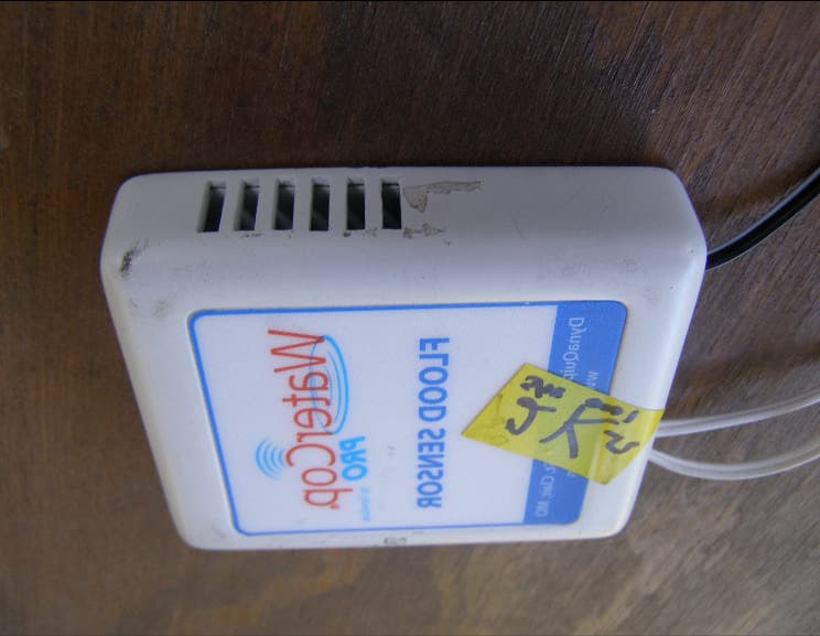
Feb 21, 2010Flood Sensor
Equipment Class
DSC - Part 15 Security/Remote Control Transmitter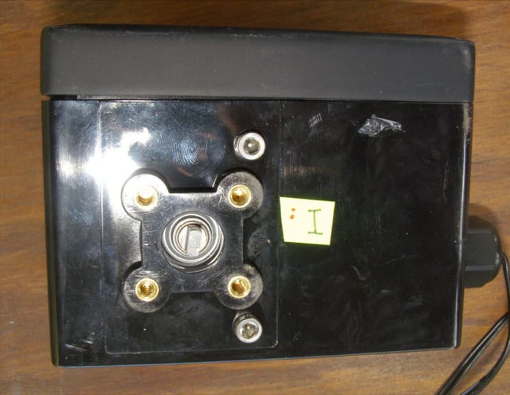
ONCWPACT
Feb 21, 2010Valve Actuator
Equipment Class
DSR - Part 15 Remote Control/Security Device Transceiver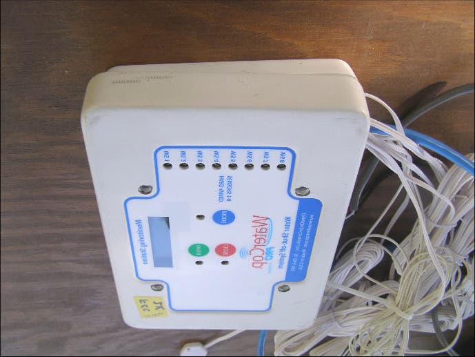
ONCWPMS
Feb 20, 2010Monitoring Station
Equipment Class
DSR - Part 15 Remote Control/Security Device Transceiver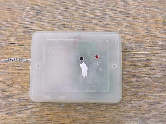
ONCWCK100
Oct 03, 1999Emergency Shut-Off Leak Detection System
Equipment Class
DSC - Part 15 Security/Remote Control Transmitter