OND5615HSA WIRLESS HANDSET SYSTEM
Emkay Innovative Products, Taiwan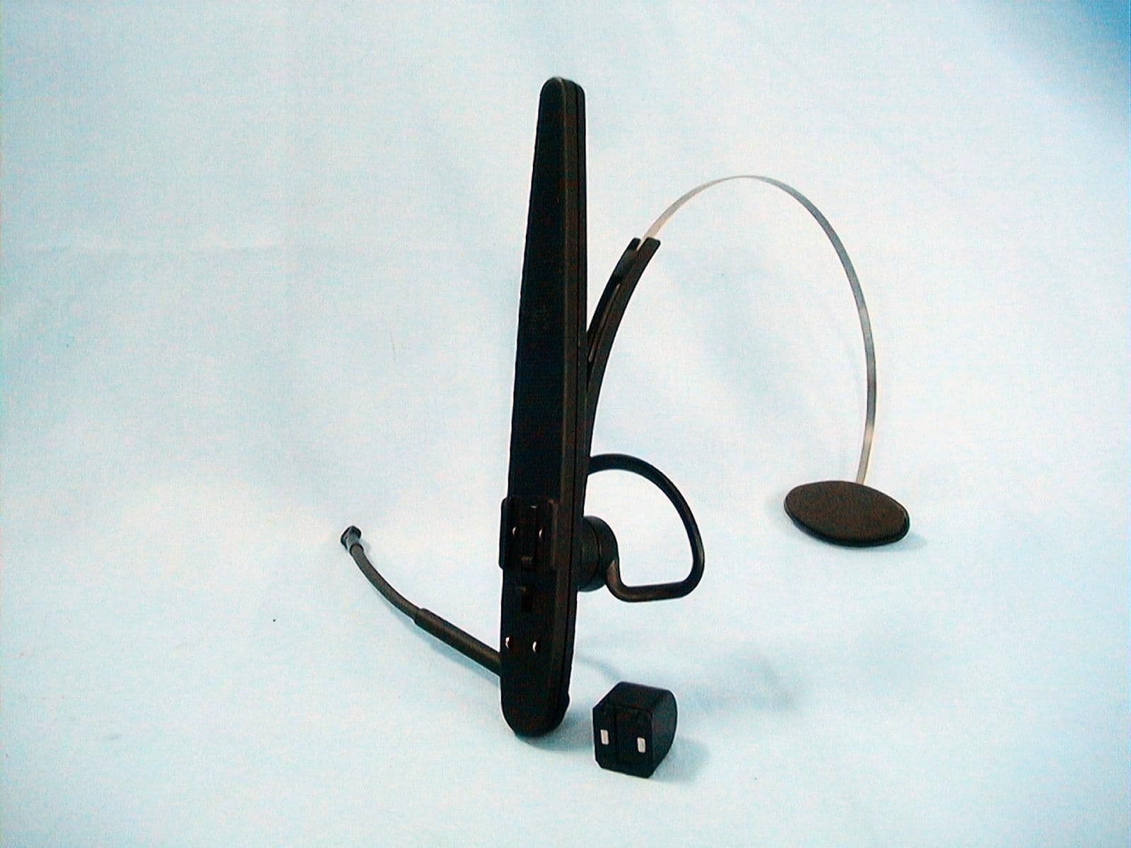
Click to zoom
Application Details
- Equipment Class
- TBF - Licensed Broadcast Transmitter Held to Face
- Date of Grant
- Feb 14, 2000
- Application Purpose
- Original Equipment
- Date of Application
- Jan 30, 2000
- Equipment Note
- A WIRLESS HANDSET SYSTEM
- Frequency Range
- 174.00000000 - 174.90000000
- Country
- Taiwan
Documents & Files
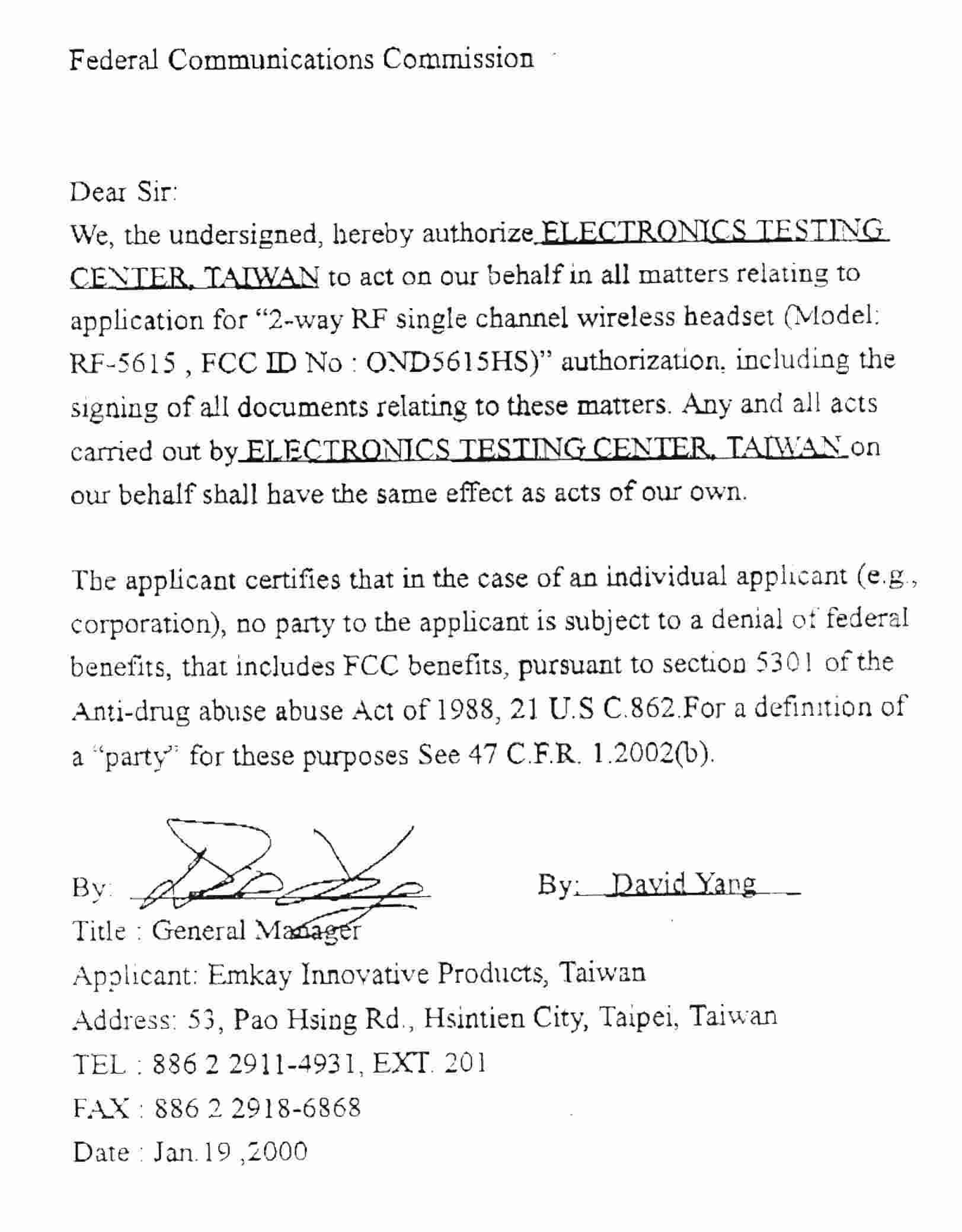
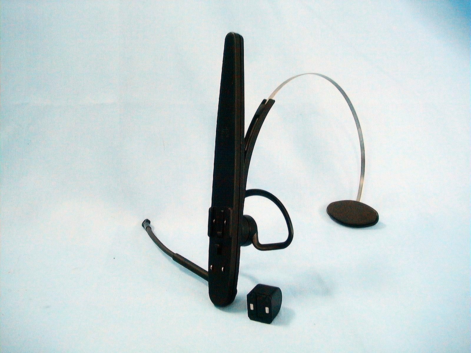
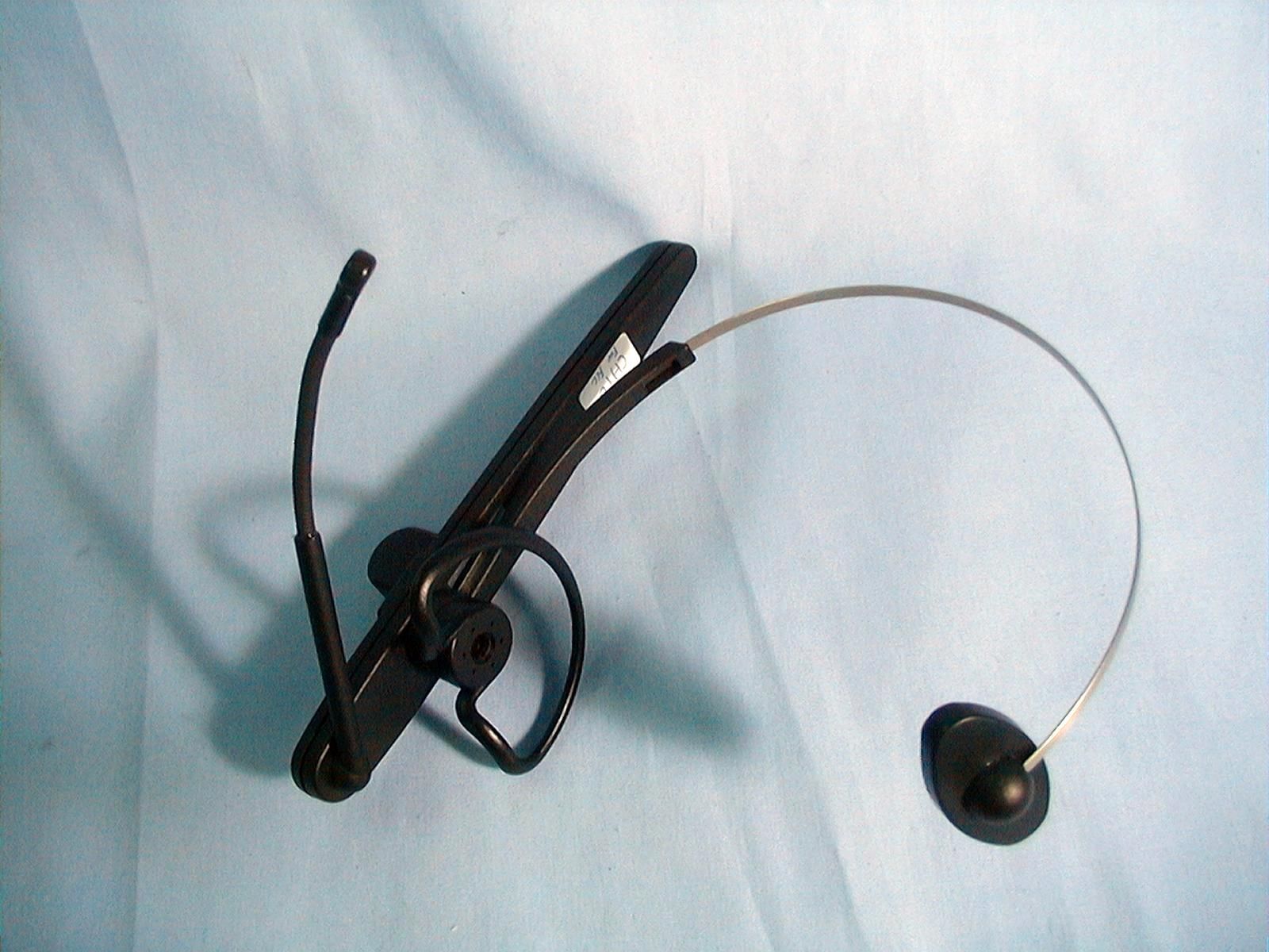
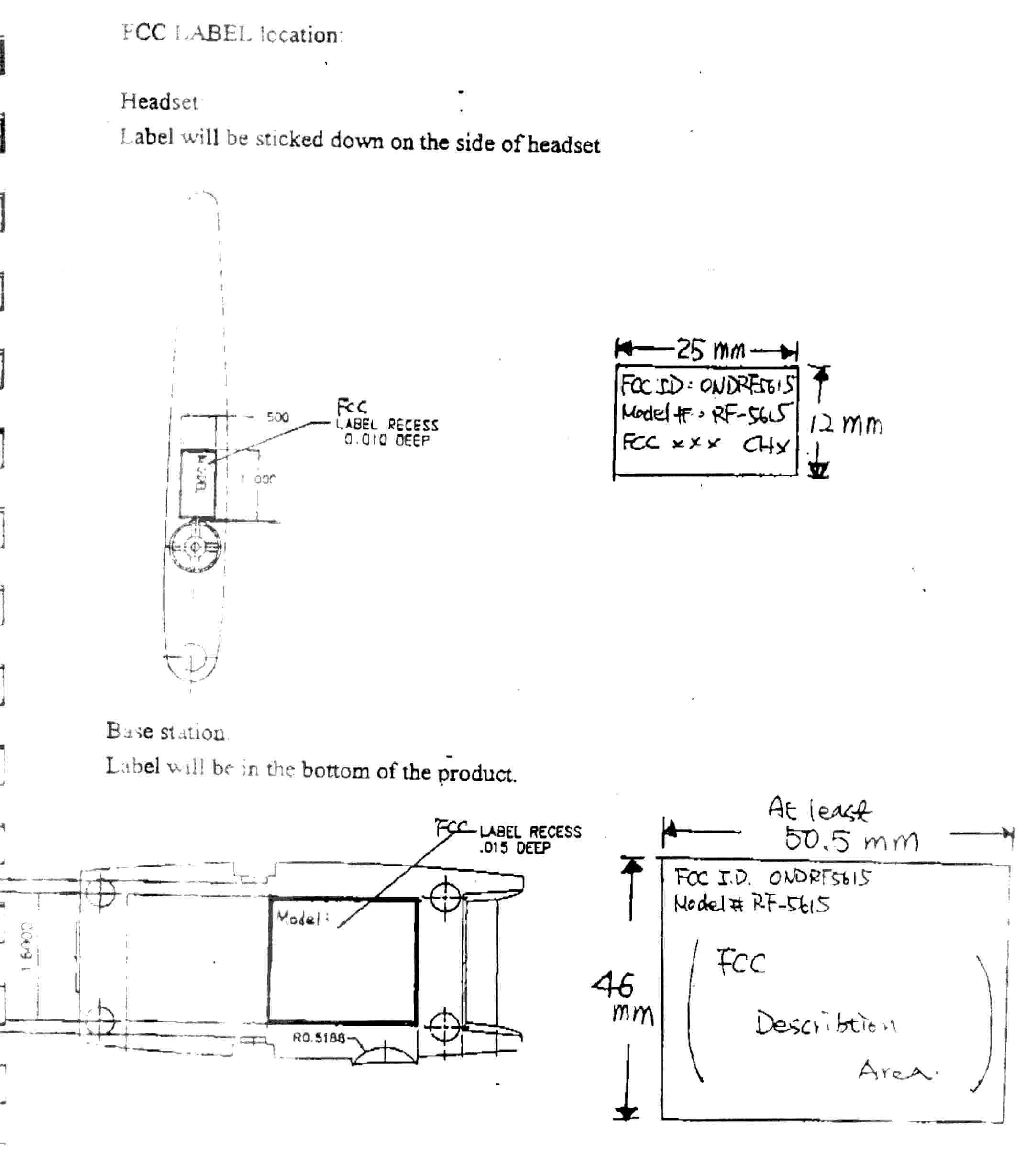
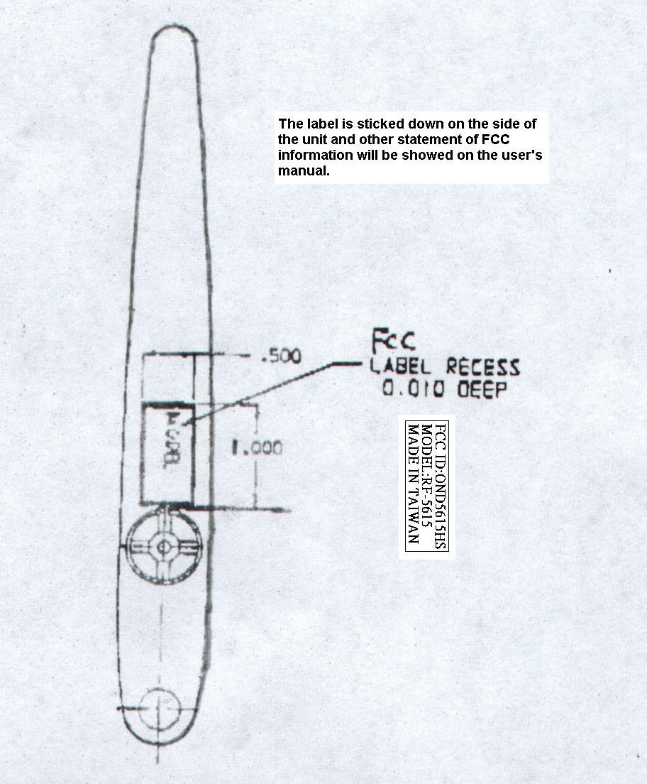
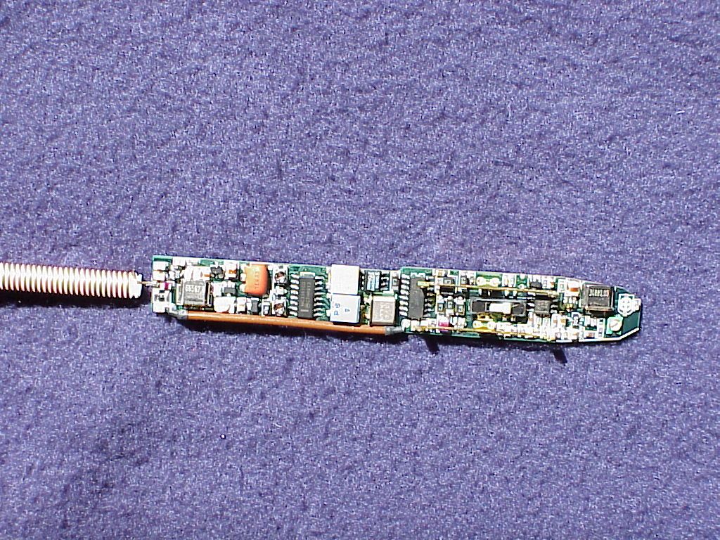
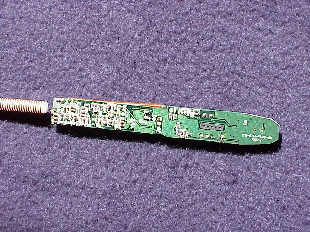

Document Text
Text extracted from the exhibit documents filed with the FCC. Open a document above to read the original.
Users Manual
RF-5615 OPERATING INSTRUCTIONS The RF-5615 is a single channel, full-duplex radio frequency wireless headset microphone, with a range greater than 25 feet. The RF-5615 Wireless Headset System Includes: Headset Base Station DC 9V Adapter Audio Cable Phone Line (2) Phone Jack Splitter Spare Battery To prepare to use your system you must first charge the headset battery in the Base Station. Make sure you have all the components listed on the above list and proceed through the step-by- step instructions. Step 1. Base Station Location The Base Station should be accessible for charging your headset and spare battery. Suggested location: to the side of your computer with line-of-sight to your headset. Please allow four inches separation between the Base Station and your monitor or CPU if possible. Step 2. Connections i.Wall Adapter:Plug the DC Adapter plug into the jack marked 9V DC on the base station and the transformer into the AC wall outlet. ii. Audio Cable:Connect the red Microphone plug into the jack marked PC MIC on the base station, and the plug the other end into the microphone jack of your the speaker jack of the soundcard on your computer. Note:If you want to use your external speakers, plug the external speakers into the jack of the Base Station labeled E iii.Telephone:1.)Unplug your telephone line from your phone and plug it into the 2.)Plug one of the black Phone Lines into a slot of the Phone Jack 3.)Plug the last black Phone Line into the remainging Phone Jack Step 3. Operation i.CONFIRM ALL SWITCHES ARE IN CORRECT POSITION. ii.Computer:When using the headset for computer use, you can put the slide switch on O - Off/Charge I - Microphone Only II - Microphone and Speaker iii.Telephone:To make a telephone call, push down on the TEL/PC silver button button again. Note:When you make a telephone call, your computer microphone connection becomes muted. The computer microphone is rec iv.Volume:You can adjust the speaker volume by turning the silver VOLUME v. Ext. Speaker:If you want to use your external speaker, push the PC/EXT button headset speaker, push the same PC/EXT button again, and the headset option is recovered. vi.Charging:The headset battery charges when the headset is placed into the Base allow eight hours for complete charging. Step 4. Headset Overview Your lightweight headset is designed for extended periods of comfortable wear. Simply place your ear through the loop, and slowly release the headband until the temple piece rests on the opposite side of your head. The unique design allows for right or left side preference. Simply adjust the earloop and microphone boom left or right (180 ) to select side preference (clockwise for right, counter-clockwise for left). You will also notice that the headband adjusts up or down for a more comfortable fit. The optimum microphone position should be about 10mm (thumb s width) distance from the side of your mouth and the tip of the microphone boom.
Block Diagram
12345678 A B C D 87654321 D C B A Title NumberRevisionSize A3 Date:10-Sep-1999Sheet of File:C:\WINDOWS\Desktop\MyDesign.ddbDrawn By: 2 2-WAY SINGLE RF HEADSET BLOCK DIAGRAM 12 A SPEAKER MICROPHONE ANTENNA LNA DUPLEX COMPANDER POWER SWITCH AMP f=174MHz ~ 174.9MHz BAND PASS FILTER MIXER BW= +/- 4MHz 10.7MHz IF AMP AMP 3-POLE DENNY CHOU FILTER 10.7MHz DEMODULATION HPF Fundamental frequency=34.8MHz ~ 34.98MHz ~ Local OSC. frequency=174MHz ~ 174.9MHz BW= +/- 4MHz ~ ~ ~ ~ ~ ~ ~ ~ ~ Fundamental frequency=66.433MHz ~ 66.733MHz ~ Local OSC. frequency=199.3MHz~ 200.2MHz ~ ~ ~ BPF RF-5615 X5 RX Frequency=210MHz ~ 210.9MHz
Operational Description
The EUT is a frequency modulation Wireless Headset System with following features : Operation Frequency Range: 174.0 to 174.9MHz for headset unit, 210.0 to 210.9 MHz for Base unit. Type of Modulation: FM, 12KF3E for headset unit and 35KF3E for base unit This wireless headset system is designed for two way communication, the headset unit with a microphone can modulate the voice to RF carrier and transmit it to the base unit, and the base unit receives the RF signals and demodulates the voice to send to any audio devices with an audio input terminal, for example a speaker or stereo. Also, the base unit has a microphone jet, to which a microphone can connect, and the user can use this to send a voice signal to the one who wears the headset. A special application is connecting the audio out to the line in jet of a sound card of a PC, so the voice recognition is avaible with a software.
Schematics
12345678 A B C D 87654321 D C B A Title NumberRevisionSize A3 Date:10-Sep-1999Sheet of File:C:\WINDOWS\Desktop\MyDesign.ddbDrawn By: 2-WAY RF SINGLE CHANNEL HEADSET CIRCUIT 4-1 DENNY CHOU R12 18K R10 open R11 680 L7 47n C30 5.6p C29 18p L5 47n L6(1008) 820n L4 47n C28 5.6p C27 1n C22 15p C19 10p C24 14p C26 1n C25 5.6p C21 3p C23 2p Q2 AT30533 R14 10K R15 10K R16 150 VCC C13 open C20 18p C18 2.7p L3 47n L1(1008) 1.2u L2 120n VCC Q1 AT30533 C15 39p C14 5-30p Y1 34.xMHz(3rd) R13 22K C17 1n VCD MA45438 CR1 MA4CP101A C16 1n GCELLin 1 RECTin 2 EXPcap 3 EXPout 4 Vcc 16 COMPc2 15 COMPin 14 COMPc1 13 Vref 5 Iref 6 GND 7 PD/MU 8 RECTin 12 GCELLin 11 COMPout 10 S DODE 9 IC1 NE578 + C10 2.2u + C11 2.2u R9 22K C12 2.2n R8 150K R7 33K + C8 2.2u R3 1M 1% R4 10K R2 2.7K R1 1K R6 10K R5 22K + C7 2.2u + C6 2.2u + C3 2.2u C39 1n C2 150p C1 1u C5 1n VCCVCC MIC. NR-3160 VCC L17 47n L15 150nH L14 47n L16 47n C35 openC37 5p C36 10p C34 10p Q3 AT31033 L18 56n C38 5p C41 1n C40 5p R17 56K R18 910 R19 3.3K Vc L19 22n L20 22n C44 3.3p C46 1000p C45 12p C43 18p C42 56p C50 1n Q4 2SC2733 L22 39n C47 3p C52 39p R22 680 R20 470 Vc R21 33K C48 24p C49 1n L23 470n C55 3-10p Y2 66.xMHz C53 39p L24 680n C54 5p SPK SPEAKER C74 0.1u C73 1u(0805) OUT 1 SNS 2 SHDN 3 GND 4 IN 8 IN 7 +5V 6 ER 5 IC4 LP2951 R38 78.7K R39 90.9K C76 100n C75 100n VCC C78 1u(0805) S1 SW BAT 2.6V C57 0.1u Q5 2SC2734 L25 2.7u(1008) C58 1n C59 22p R25 1.5K R24 200 R23 30K Vc C56 56p F3 10.7MHz C60 0.1u Q6 2SC2733 C61 1n R27 470 R26 30K Vc C69120p R28 4.7K OSCin 1 OSCout 2 MIXout 3 Vcc 4 Mixerin 16 Gnd 15 Mute 14 ScanC 13 LIMin 5 Dec 6 Dec 7 Quad 8 Squelch 12 FILout 11 FILin 10 DEMOout 9 IC2 MC3361CD Y4 10.245MHz F1 455KHZ C62 68pC63 220p C64 0.1u C65 0.1u C66 0.1u F2 455K Vc R31 4.7K R36 470K R32 100K R30 1K R29 100K D1 MA111 + C67 0.47u C68 100n VR33 50K C70 120p C72 10n C71 4.7n R35 100K R34 4.7K GND1 1 AUIN1 2 AUIN2 3 GND2 4 VCC 8 AUO1 7 AUO2 6 GND 5 IC3 TDA7050T VR37 50K Vc Vc OFF OFF TX 2WAY1 1 2 2 3 3 L11(0805) 220nH L12(1008) 0 ANT ANTENNA C79 open C77 5p + C9 2.2u RF-5615(36.229.01-x)3.0 Vc TP2 TP3TP4TP5 TP6 TP8 TP7 TP9TP11 TP10 TP12 TP13 TP1 Name SINGLE1.PRJ Name rftelpho.prj R40 open R37 open R33 open R41 open
Test Report
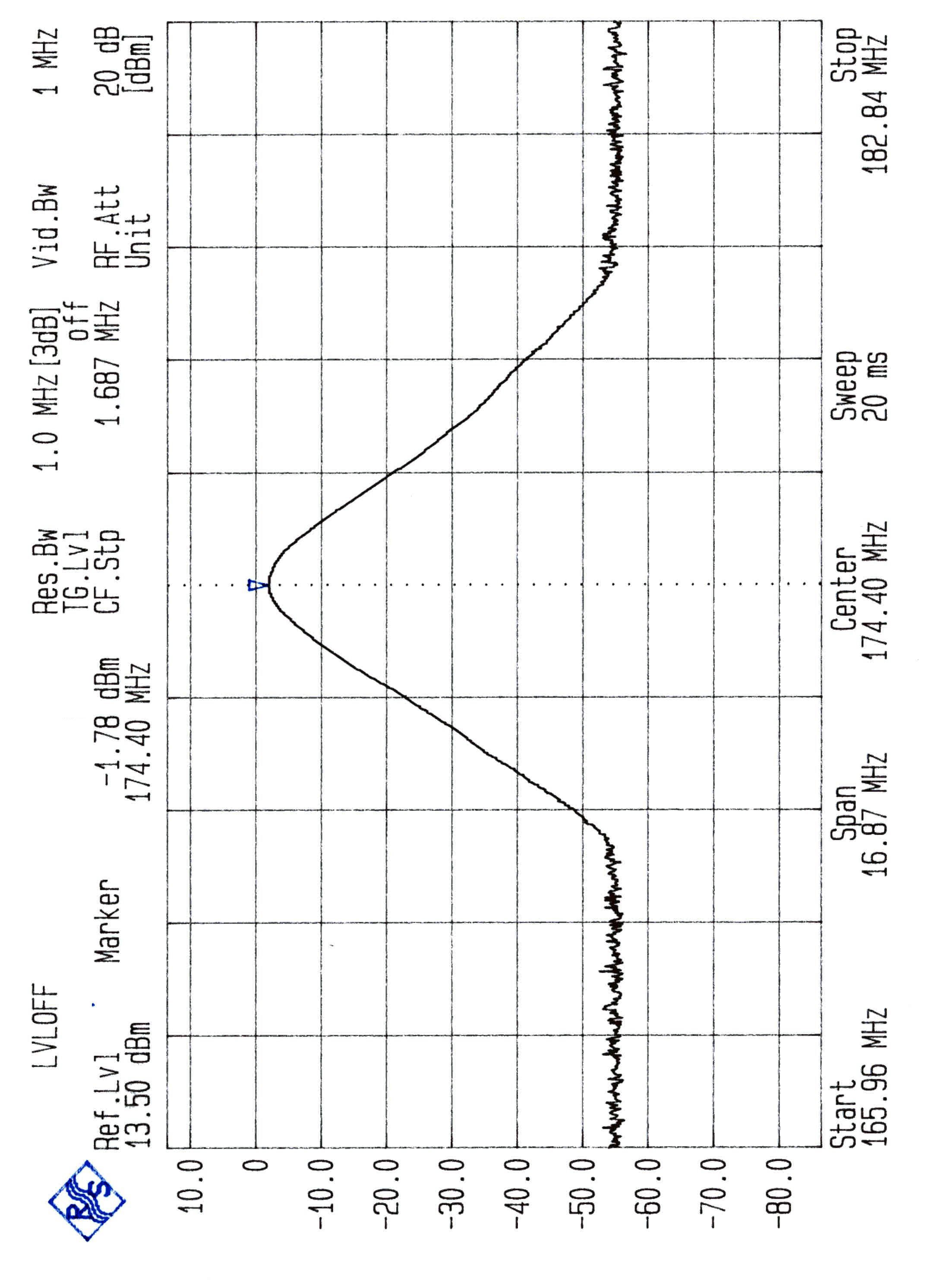
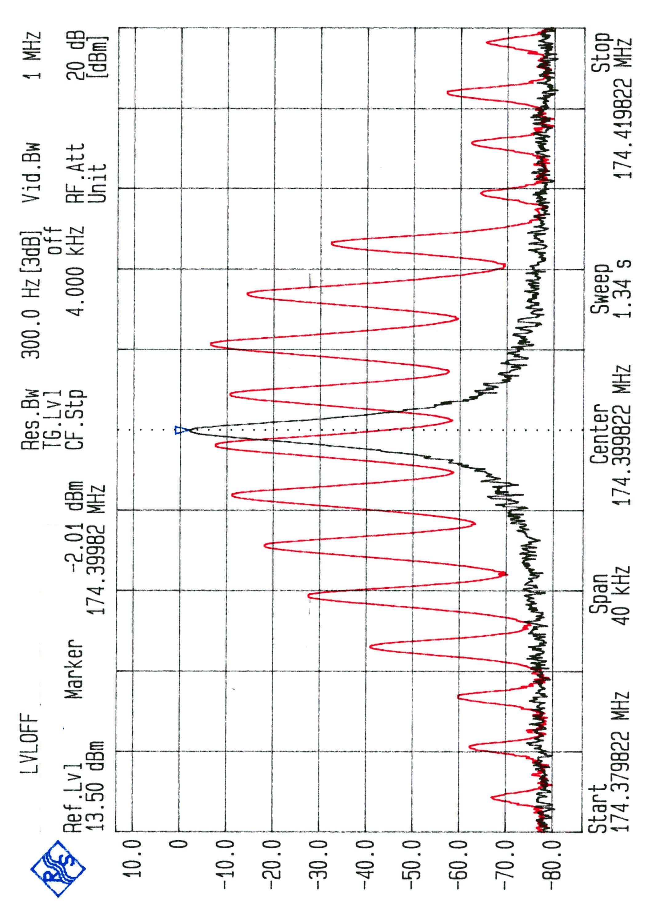
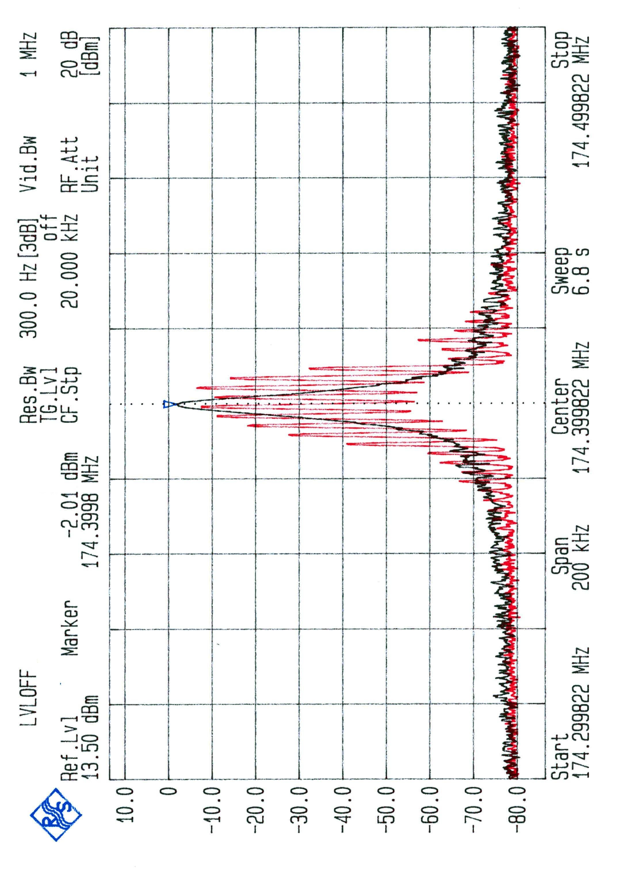
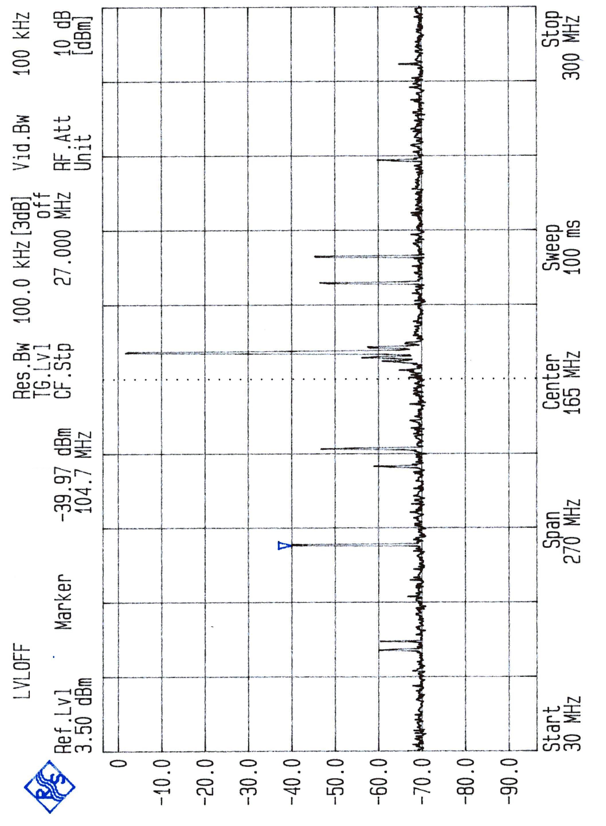
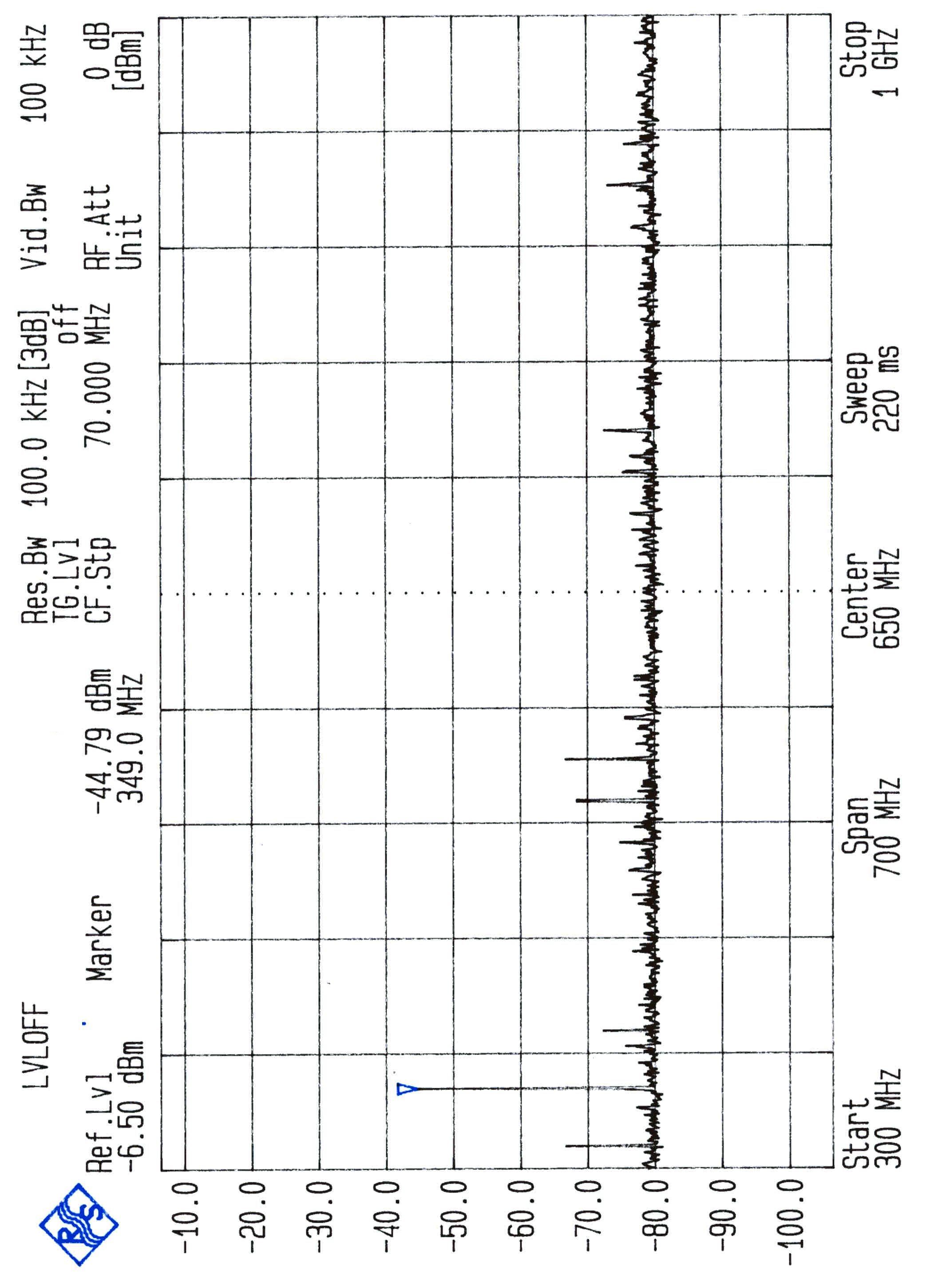
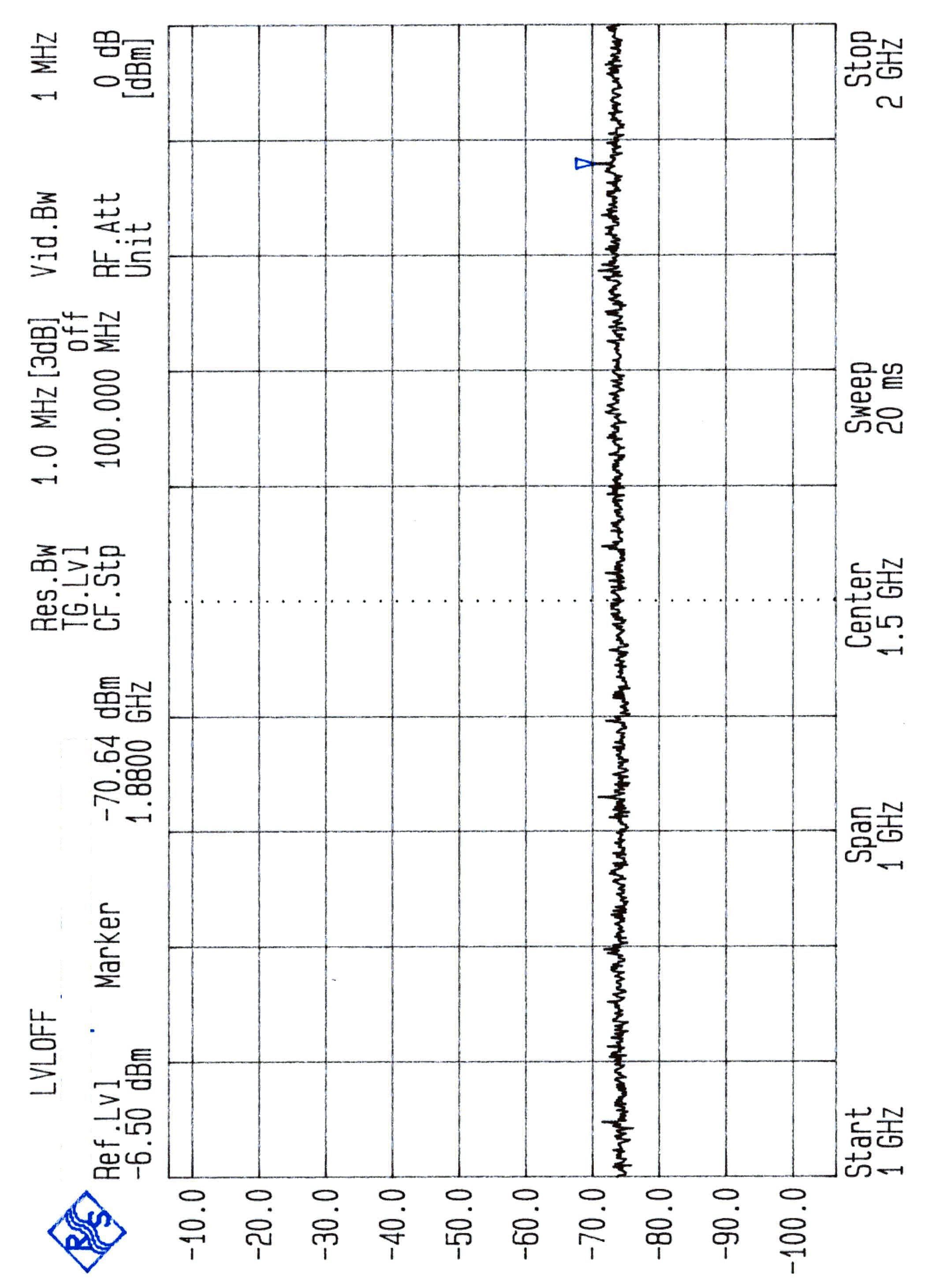
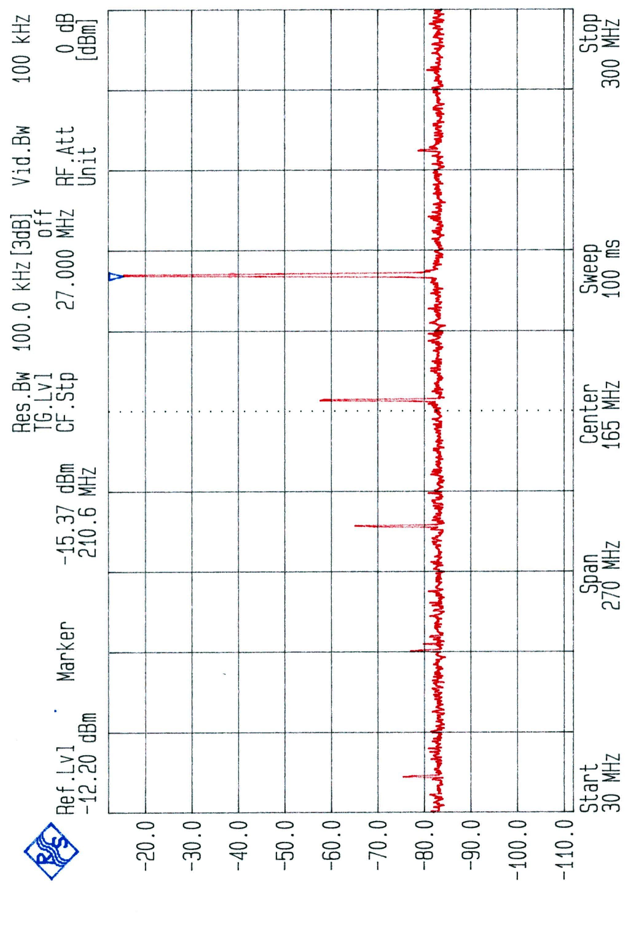
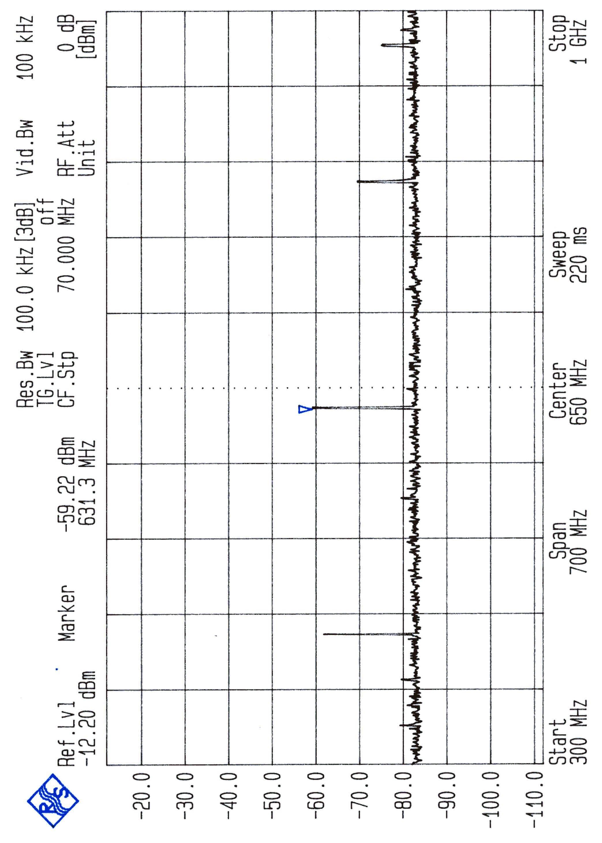
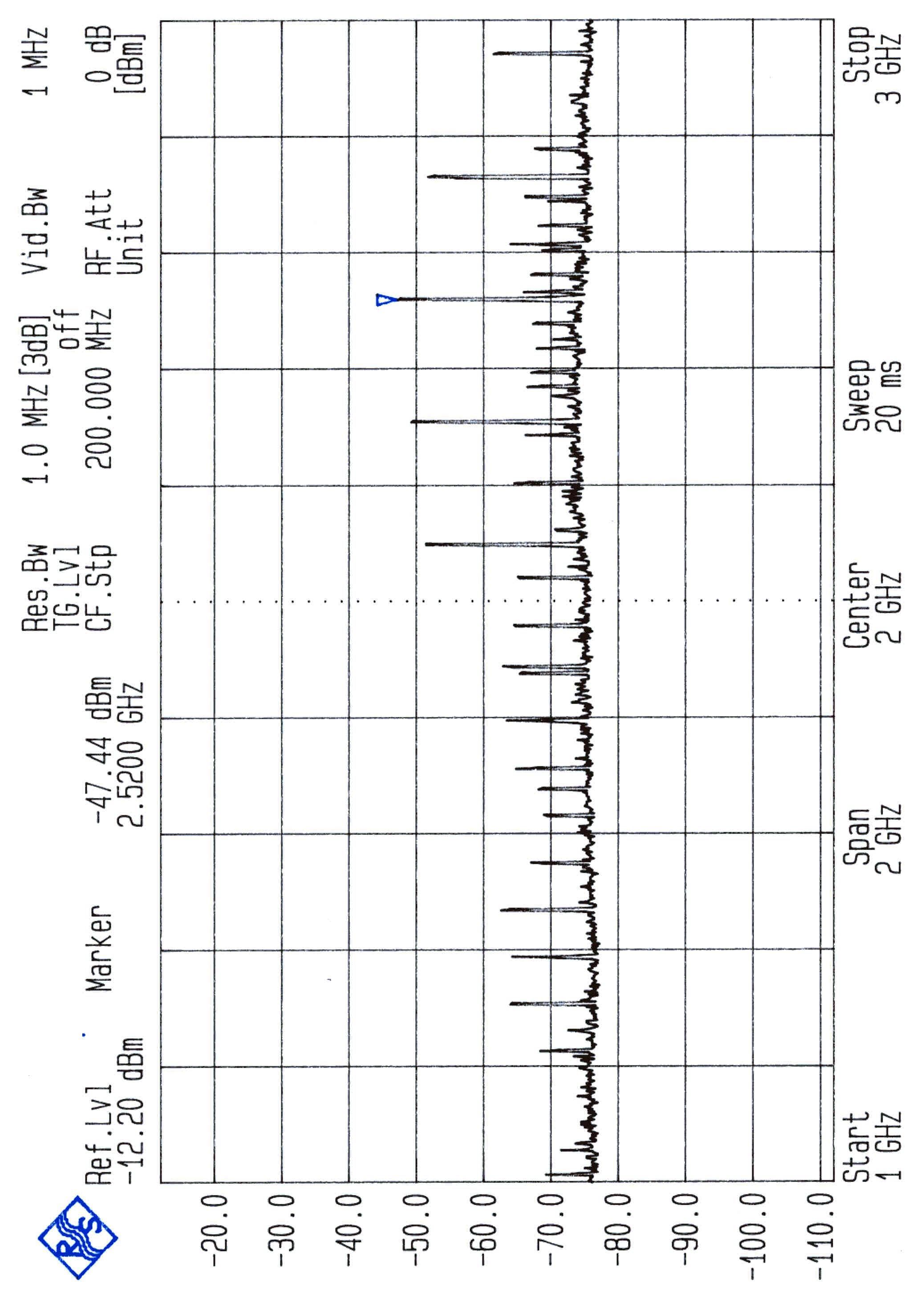
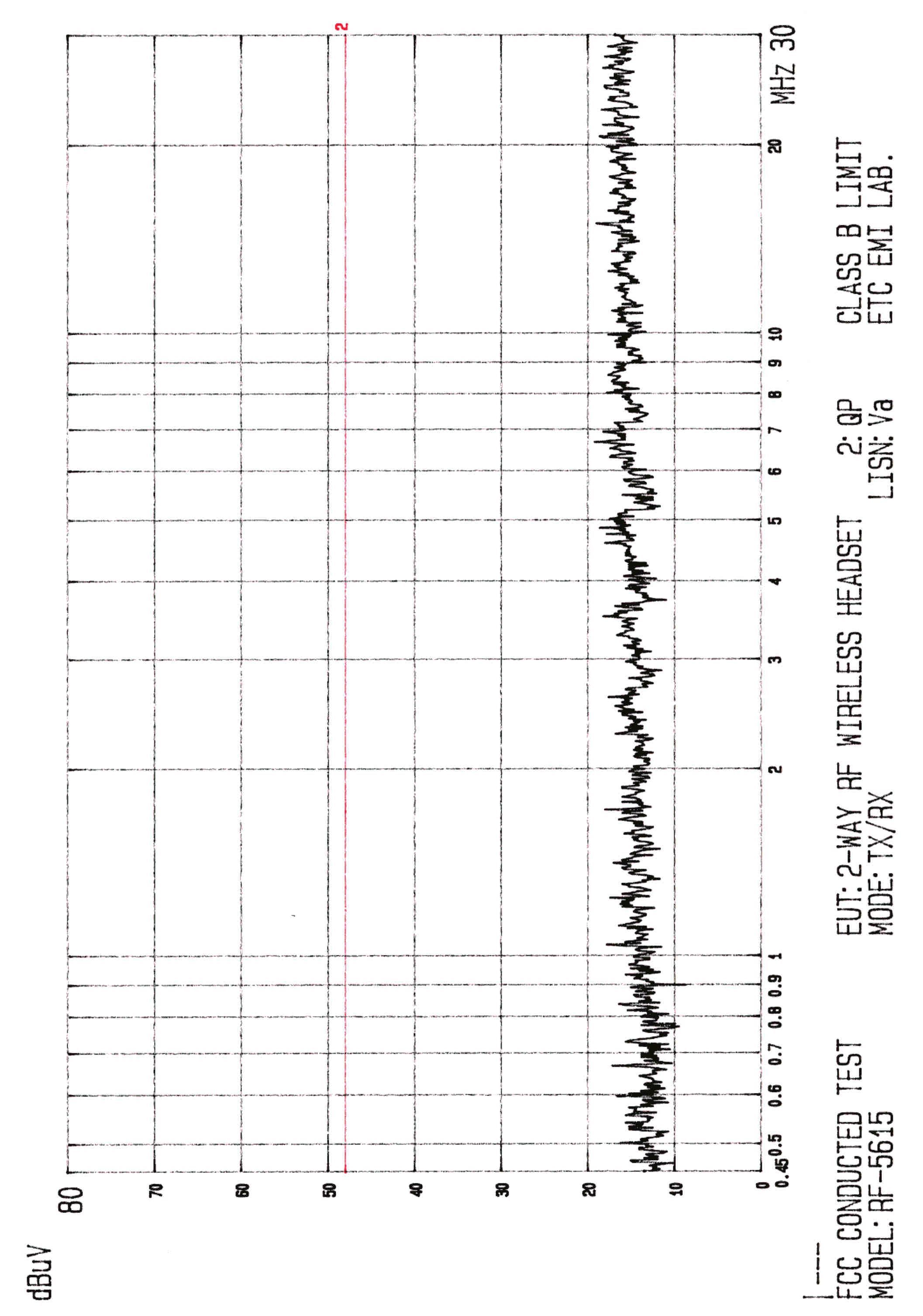
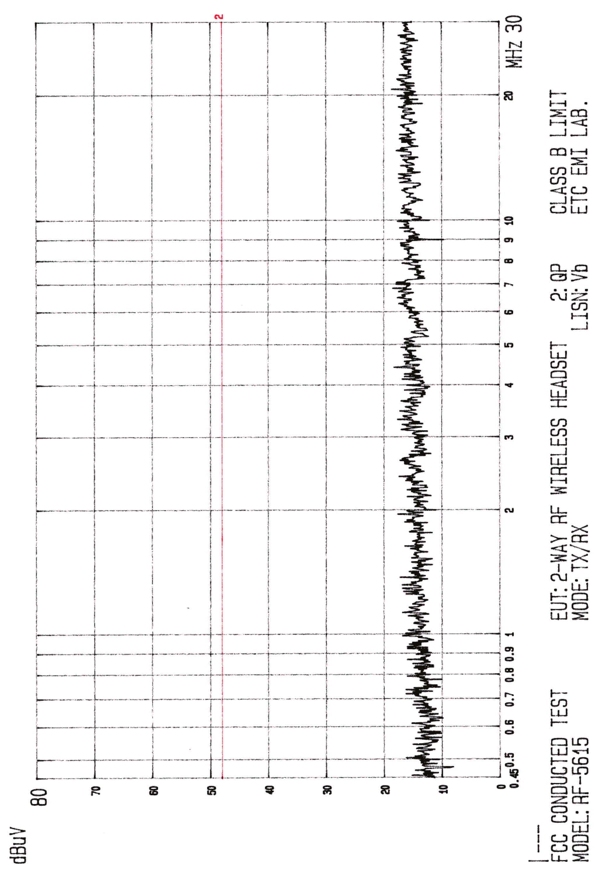
FCC ID.:OND5615HS FCC Part 74 Subpart H EMI TEST REPORT of E.U.T. : Wireless Headset System FCC ID. : OND5615HS MODEL : RF-5615 Working Frequency : 174.0-174.9 MHz for APPLICANT : EMKAY INNOVATIVE PRODUCTS, TAIWAN ADDRESS: 53, PAO HSING RD., HSINTIEN CITY, TAIPEI, TAIWAN, R.O.C. Test Performed by ELECTRONICS TESTING CENTER, TAIWAN NO. 8 LANE 29, WENMIMG ROAD, LOSHAN TSUN, KWEISHAN HSIANG, TAOYUAN, TAIWAN, R.O.C. Tel:(03)3280026-32 Fax:(03)3280034 Report Number : ET88R-07-021-01 FCC ID.:OND5615HS TEST REPORT CIRTIFICATION Applicant: EMKAY INNOVATIVE PRODUCTS, TAIWAN 53, PAO HSING RD., HSINTIEN CITY, TAIPEI, TAIWAN, R.O.C. Manufacturer: EMKAY INNOVATIVE PRODUCTS, TAIWAN 53, PAO HSING RD., HSINTIEN CITY, TAIPEI, TAIWAN, R.O.C. Description of EUT: a) Type of EUT: Wireless Headset System b) Trade Name: N/A c) Model No.: RF-5615 d) FCC ID: OND5615HS e) Working Frequency: 174.0-174.9 MHz f) Power Supply: DC 2.5V Regulation Applied : FCC Rules and Regulations Part 74 Subpart H (1997) & Part 15 Subpart B I HEREBY CERTIFY THAT; The data shown in this report were made in accordance with the procedures given in ANSI C63.4 and the energy emitted by the device was founded to be within the limits applicable. I assume full responsibility for accuracy and completeness of these data. Issued Date :JAN. 27, 2000 Test Engineer : ( Jeff Chuang ) Approve & Authorized Signer : Will Yauo, Supervisor EMI Test Site of ELECTRONICS TESTING CENTER, TAIWAN ETC Report No.:ET88R-07-021-01Sheet 1 of 32 Sheets FCC ID.:OND5615HS Table of Contents Page 1. GENERAL INFORMATION........................................................................................................................................3 1.1P RODUCT DESCRIPTION..........................................................................................................................................3 1.2C HARACTERISTICS OF DEVICE: ...............................................................................................................................3 1.3T EST METHODOLOGY.............................................................................................................................................3 1.4T EST FACILITY........................................................................................................................................................3 2. REQUIREMENTS OF PROVISIONS .........................................................................................................................4 2.1D EFINITION.............................................................................................................................................................4 2.2F REQUENCIES AVAILABLE......................................................................................................................................4 2.3R EQUIREMENTS FOR RADIO EQUIPMENT ON CERTIFICATION...................................................................................4 2.4L ABELING REQUIREMENT.......................................................................................................................................5 3. OUTPUT POWER MEASUREMENT.........................................................................................................................6 3.1P ROVISION APPLICABLE..........................................................................................................................................6 3.2M EASUREMENT PROCEDURE..................................................................................................................................6 3.3T EST DATA.............................................................................................................................................................6 3.3R ESULT CALCULATION............................................................................................................................................7 3.4O UTPUT POWER TEST EQUIPMENT..........................................................................................................................7 4. MODULATION CHARACTERISTICS ......................................................................................................................8 4.1P ROVISIONS APPLICABLE........................................................................................................................................8 4.2M EASUREMENT METHOD........................................................................................................................................8 4.3M EASUREMENT INSTRUMENT.................................................................................................................................9 4.4M EASUREMENT RESULT.........................................................................................................................................9 5. OCCUPIED BANDWIDTH OF EMISSION .............................................................................................................11 5.1P ROVISIONS APPLICABLE......................................................................................................................................11 5.2M EASUREMENT METHOD......................................................................................................................................11 5.3O CCUPIED BANDWIDTH TEST EQUIPMENT............................................................................................................11 5.4B ANDWIDTH MEASURED.......................................................................................................................................12 5.4.1Input Level Derived .........................................................................................................................................12 5.4.2O CCUPIED BANDWIDTH PLOTTED.........................................................................................................................12 6. SPU…
Text truncated - open the document above for the full version.
Contact Information
Applicant
David Yang(General Manager)
886-2-2911-4931Fax: 886-2-2918-6868
Technical Contact
ELECTRONICS TESTING CENTER, TAIWANK. C. CHEN
[email protected]886-2-26023052
NO. 34, LIN 5, DING FU TSUNG, LINKOU HSIANG · TAIPEI HSIEN · Taiwan
Non-Technical Contact
ELECTRONICS TESTING CENTER, TAIWANK. C. CHEN
[email protected]886-2-26023052
Test Firm
Electronics Testing Center, TaiwanWill Yauo
Technical Specifications
| # | Rule Parts | Frequency Range | Power Output | Emission | Tolerance |
|---|---|---|---|---|---|
| 1 | 74.861 | 174 MHz - 174.9 MHz | 1.50 mW | 12KOF3E | 0.0050000000 % |
Other Applications from Emkay Innovative Products, Taiwan
ONDRF5615
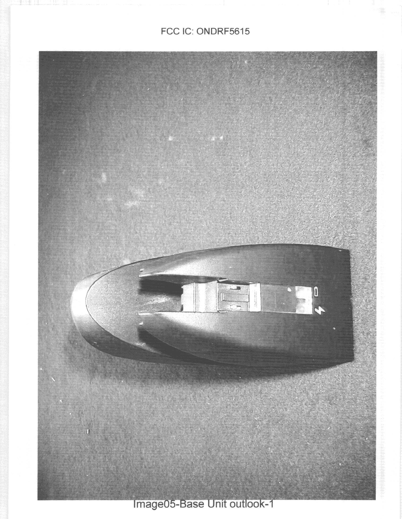
Feb 15, 2000Base Unit
Equipment Class
TBC - Licensed Broadcast Station Transmitter