ONGORBITZ50WCDMA Mobile Phone
MAXWEST TELECOM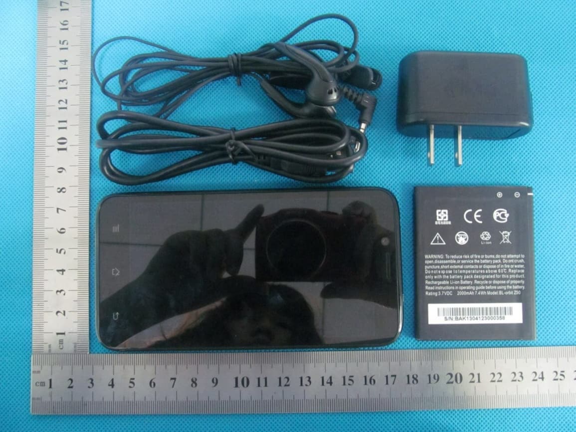
Click to zoom
Application Details
- Equipment Class
- DSS - Part 15 Spread Spectrum Transmitter
- Date of Grant
- May 29, 2013
- Application Purpose
- Original Equipment
- Date of Application
- May 29, 2013
- Equipment Note
- WCDMA Mobile Phone
- Frequency Range
- 2402.00000000 - 2480.00000000
- Company
- MAXWEST TELECOM
- Country
- China
Documents & Files
Document Text
Text extracted from the exhibit documents filed with the FCC. Open a document above to read the original.
Users Manual
WCDMA MOBILE PHONE User Manual BRAND NAME: MAXWEST MODEL NAME: ORBIT Z50 FCC ID:ONGORBITZ50 ORBIT Z50 User Manual Android 4.1(Jelly Bean) is the Operating System for your Touch Screen Smartphone. -2- INTRODUCTION Thanks for choosing the Maxwest, Dual SIM Android smart phone based on 1.2 GHz Quad Core Snapdragon Processor. This smart phone is running on Android OS, v4.1 (Jelly Bean). If you’d like your phone to live a long and fruitful life, please read this guide carefully and keep it for future reference. You never know when you might need it. And don’t worry if the pictures we use to demonstrate your phone’s functions look a little different from what you see on its screen. It’s the functions that matter. * The Manufacturer reserves the right for the changes in the manual without advanced notice . -3- Table of Contents 1 Safety........................................................................ 4 1.1 Safety Precautions..................................................4 1.2 Using your phone safely..........................................4 2 Understanding your Phone........................................... 8 2.1 Your Phone.............................................................8 2.2 Description Icons....................................................9 2.3 Inserting & Removing the battery............................10 2.4 Charging the battery...............................................11 2.5 Power ON/OFF........................................................11 2.6 Enter Main Menu....................................................11 2.7 Enter Sub Menu......................................................10 2.8 Use Notification Panel.............................................10 2.9 Expand Main Interface............................................10 2.10 Add icons on the main interface..............................10 2.11 Move icons on the main interface............................11 2.12 Delete icons on the main interface.............................11 2.13 Change wallpapers..................................................11 2.14 Install APK through File Manager.............................11 3 Using your Phone........................................................ 12 3.1 Main Menu & Its Functions.....................................12 3.2 Wi‐Fi Direct............................................................12 4 Inputting Text............................................................. 22 5 Maintenance.............................................................. 23 6 Taking Care of your Device............................................ 24 1 1 -4- S S a a f f e e t t y y 1 1 . . 1 1 S S a a f f e e t t y y P P r r e e c c a a u u t t i i o o n n s s Please read through the following briefings carefully, and act in accordance with these rules, so as to prevent causing any danger or violating any law. • Your mobile phone model has been designed to compile with applicable safety requirements for exposure to radio waves. The radio wave exposure guidelines employ a unit of measurement called Specific Absorption Rate (SAR). The recommended SAR limit for mobile handset is 1.6 W/Kg averaged over a 6 minutes period and taken over a volume containing a mass 1g of human tissue. • The highest SAR value for this mobile phone model is 1.482 watt/kg averaged over a 6 minutes period and taken over a volume containing a mass 1g of human tissue. • Use cell phone when the signal strength is good. Keep your calls short or instead use headset or send a text message. This advice applies especially to children, adolescents and pregnant women. • If you are using a Bluetooth headset device, please make sure it has a low power emitter. 1 1 . . 2 2 U U s s i i n n g g y y o o u u r r p p h h o o n n e e s s a a f f e e l l y y On The Road Using a phone while driving is illegal in many countries. Please follow local laws and drive safely at all times. Near Sensitive Electronics Don’t use your phone near sensitive electronic equipment – particularly medical devices such as pacemakers – as it could cause them to malfunction. It can also interfere with the operation of fire detectors and other automatic‐control equipment. For more information about how your phone affects pacemakers or other electronic equipment, please contact the manufacturer or your local distributor. Your phone may cause interference when used near TVs, radios or automated office equipment. While Flying Your phone can cause interference with aircraft equipment. So it’s essential you follow airline regulations. And if airline personnel ask you to switch off your phone, or disable its wireless functions, please do as they say. In Hospital Your phone may interfere with the normal operation of medical equipment. Follow all hospital regulations and turn it off when you’re asked to by posted warnings or medical staff. At a Petrol Station Don’t use your phone at petrol stations. In fact, it’s always best to switch off whenever you’re near fuels, chemicals or explosives. Around Water Keep your phone away from water (or any other liquid). It’s not a waterproof model. Making Repairs Never take your phone apart. Please leave that to the professionals. Unauthorized repairs could break the terms of your warranty. Broken Antenna Don’t use your phone if the antenna is damaged, as it could cause injury. Around Children -5- Keep your mobile out of children’s reach. It should never be used as a toy and it might not be good for their health. Original Accessories Only use the original accessories supplied with your phone or those approved by the manufacturer. Using unapproved accessories may affect performance, make the warranty void, break national regulations on the use of mobile phones, or even cause injury. Near Explosives Turn off your phone in or near areas where explosive materials are used. Always obey local laws and turn off your phone when requested. Emergency Calls To make an emergency call your phone must be turned on and in an area…
Text truncated - open the document above for the full version.
Cover Letter(s)
May. 25, 2013 Federal Communication Commission Authorization and Evaluation Division FCC ID: ONGORBITZ50 Re: Confidentiality Request Pursuant to Sections 0.457 and 0.459 of the Commission’s Rules, the applicant hereby requests confidential treatment of information applied this application as outlined below: 1: Block Diagram 2: Circuit Diagram 3: Operational Description 4: Parts List 5: Tune Up Procedure The above materials contain trade secrets and proprietary information not customarily released to the public. The public disclosure of these matters might be harmful to the applicant and provide unjustified benefits to its competitors. The Applicant understands that pursuant to Rules 0.457, disclosure of this Application and all accompanying documentation will not be made before the date of the Grant for this application. Sincerely, MAXWEST TELECOM Contact person: ADAM YU Title: General Manager
Cover Letter(s)
Ersteller: D. Brandhorst Revision: 00 Erstelldatum: 21.06.07 Datum: 00.00.00 Seite 1 von 1 Date: May 25, 2013 Subject: Ad Hoc Mode Function Declaration FCC ID: ONGORBITZ50 To Whom it may concern, This device is acting as slave and operating in the 2.4 GHz (2412 – 2462 MHz) band. Ad Hoc function is supported but not able to operate on non-US frequencies. Please contact the one signed below or the authorized agent for this filing. Thank you. Regards , MAXWEST TELECOM Contact person: ADAM YU Title: General Manager
Cover Letter(s)
MAXWEST TELECOM 11037 warner ave #201 fountain valley, ca, 92708 USA Date: May 25, 2013 Statement We, MAXWEST TELECOM states that our device, FCC ID: ONGORBITZ50, has no space to put the label except the battery compartment of this device. It is visible to the users as they purchase the products and install the battery. Regards Company: MAXWEST TELECOM Contact Person: ADAM YU Title: General Manager
Cover Letter(s)
Ersteller: D. Brandhorst Revision: 01 Erstelldatum: 07.03.2008 Datum: 27.06.2011 Seite 1 von 1 MAXWEST TELECOM 11037 warner ave #201 fountain valley, ca, 92708 USA PHOENIX TEST-LAB GmbH Product Certification Königswinkel 10 D 32825 Blomberg Date: May 25,2013 FCC ID: ONGORBITZ50 Subject: Attestation Letter “Declaration of Conformity” Dear Sirs, Our products with the above FCC ID: ONGORBITZ50 are defined as composite device. The transmitter is authorized under the “Certification” procedure. The device is also defined as “PC Periphery” acc to §15.101 Equipment authorization of unintentional radiators, where we hereby declare, that we apply and follow the “FCC Declaration of Conformity” procedure, based on testing from a FCC accredited testing laboratory or involvement of a CB. And we will settle the JBP parts with DOC. If you have any questions, please feel free to contact me at the address shown below. Yours sincerely, Regards , MAXWEST TELECOM Contact person: ADAM YU Title: General Manager
External Photos
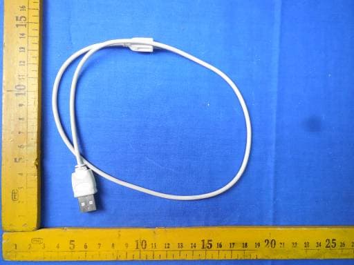
ORBIT Z50 External Photos TOTAL VIEW OF EUT TOP VIEW OF EUT BOTTOM VIEW OF EUT FRONT VIEW OF EUT BACK VIEW OF EUT LEFT VIEW OF EUT RIGHT VIEW OF EUT
ID Label/Location Info
FCC ID W Label Lo WCDMA MO Model: ORB Trade Nam FCC ID: O N ocation OBILE PHO BIT Z50 e: MAXWE S NGORBITZ5 ONE ST 50
Internal Photos
ORBIT Z50 Internal Photos OPEN VIEW OF EUT-1 BT & WIFI Antenna GSM & WCDM A OPEN VIEW OF EUT-2 OPEN VIEW OF EUT-3 INTERNAL VIEW OF EUT-1 INTERNAL VIEW OF EUT-2
Test Report
Report No.: AGC00117130501FE03 Page 1 of 52 FCC Test Report Report No.: AGC00117130501FE03 FCC ID : ONGORBITZ50 APPLICATION PURPOSE : Original Equipment PRODUCT DESIGNATION : WCDMA MOBILE PHONE BRAND NAME : MAXWEST MODEL NAME : ORBIT Z50 CLIENT : MAXWEST TELECOM DATE OF ISSUE : May 23,2013 STANDARD(S) : FCC Part 15 Rules REPORT VERSION : V1.0 Attestation of Global Compliance (Shenzhen) Co., Ltd CAUTION: This report shall not be reproduced except in full without the written permission of the test laboratory and shall not be quoted out of context. Report No.: AGC00117130501FE03 Page 2 of 52 Report Revise Record Report Version Revise Time Issued Date Valid VersionNotes V1.0 / May 23,2013Valid Original Report Report No.: AGC00117130501FE03 Page 3 of 52 TABLE OF CONTENTS 1. VERIFICATION OF CONFORMITY ...................................................................................... 5 2. GENERAL INFORMATION .................................................................................................. 6 2.1. PRODUCT DESCRIPTION ........................................................................................................... 6 2.2. TABLE OF CARRIER FREQUENCYS .......................................................................................... 6 2.3. RECEIVER INPUT BANDWIDTH ................................................................................................. 7 2.4. EXAMPLE OF A HOPPING SEQUENCY IN DATA MODE ........................................................... 7 2.5. EQUALLY AVERAGE USE OF FREQUENCIES AND BEHAVIOUR ............................................ 7 2.6. RELATED SUBMITTAL(S) / GRANT (S) ....................................................................................... 8 2.7. TEST METHODOLOGY................................................................................................................ 8 2.8. SPECIAL ACCESSORIES ............................................................................................................ 8 2.9. EQUIPMENT MODIFICATIONS ................................................................................................... 8 3. MEASUREMENT UNCERTAINTY........................................................................................ 9 4. DESCRIPTION OF TEST MODES ........................................................................................ 9 5. SYSTEM TEST CONFIGURATION .................................................................................... 10 5.1. CONFIGURATION OF EUT SYSTEM ........................................................................................ 10 5.2. EQUIPMENT USED IN EUT SYSTEM ....................................................................................... 10 5.3. SUMMARY OF TEST RESULTS ................................................................................................ 10 6. TEST FACILITY .................................................................................................................. 11 7. PEAK OUTPUT POWER .................................................................................................... 12 7.1. MEASUREMENT PROCEDURE ................................................................................................ 12 7.2. TEST SET-UP (BLOCK DIAGRAM OF CONFIGURATION) ....................................................... 12 7.3. LIMITS AND MEASUREMENT RESULT .................................................................................... 12 8. 20DB BANDWIDTH ............................................................................................................ 14 8.1. MEASUREMENT PROCEDURE ................................................................................................ 14 8.2. TEST SET-UP (BLOCK DIAGRAM OF CONFIGURATION) ....................................................... 14 8.3. LIMITS AND MEASUREMENT RESULTS .................................................................................. 14 9. CONDUCTED SPURIOUS EMISSION ............................................................................... 21 9.1. MEASUREMENT PROCEDURE ................................................................................................ 21 9.2. TEST SET-UP (BLOCK DIAGRAM OF CONFIGURATION) ....................................................... 21 9.3. MEASUREMENT EQUIPMENT USED ....................................................................................... 21 9.4. LIMITS AND MEASUREMENT RESULT .................................................................................... 21 10. RADIATED EMISSION ..................................................................................................... 25 10.1. MEASUREMENT PROCEDURE .............................................................................................. 25 10.2. TEST SETUP ............................................................................................................................ 27 Report No.: AGC00117130501FE03 Page 4 of 52 10.3. TEST RESULT .......................................................................................................................... 28 11. BAND EDGE EMISSION .................................................................................................. 32 11.1. MEASUREMENT PROCEDURE .............................................................................................. 32 11.2. TEST SET-UP ........................................................................................................................... 32 11.3. TEST RESULT .......................................................................................................................... 33 12. NUMBER OF HOPPING FREQUENCY ............................................................................ 37 12.1. MEASUREMENT PROCEDURE .............................................................................................. 37 12.2. TEST SETUP (BLOCK DIAGRAM OF CONFIGURATIO…
Text truncated - open the document above for the full version.
Test Setup Photos
APPENDIX D: PHOTOGRAPHS OF TEST SETUP CONDUCTED EMISSION RADIATED SPURIOUS EMISSION
Contact Information
Applicant
ADAM YU
Test Firm
Attestation of Global Compliance Shenzhen Co. Ltd.Forrest Lei
Technical Specifications
| # | Rule Parts | Frequency Range | Power Output |
|---|---|---|---|
| 1 | 15C | 2.40 GHz - 2.48 GHz | 2.90 mW |
Other Applications from MAXWEST TELECOM
ONGASTRO55
Nov 06, 2014Mobile Phone
Equipment Class
DSS - Part 15 Spread Spectrum Transmitter
ONGASTRO4
Nov 02, 2014Mobile Phone
Equipment Class
DTS - Digital Transmission System
ONGTABPHONE76DC
Sep 21, 2014Tablet
Equipment Class
PCE - PCS Licensed Transmitter held to ear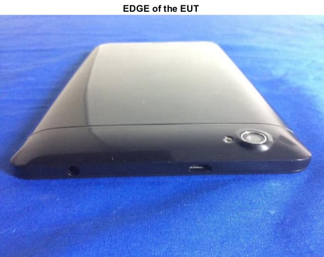
ONGVIRTUETAB7
Aug 04, 2014Tablet
Equipment Class
DSS - Part 15 Spread Spectrum Transmitter
ONGGRAVITY55
Jun 02, 2014WCDMA Mobile Phone
Equipment Class
PCE - PCS Licensed Transmitter held to ear