ONTJETIR18USReceiver/transmitter for radio control model toys
Esprit Model Inc.
Click to zoom
Application Details
- Equipment Class
- DSS - Part 15 Spread Spectrum Transmitter
- Date of Grant
- Jan 20, 2013
- Application Purpose
- Original Equipment
- Date of Application
- Jan 20, 2013
- Equipment Note
- Receiver/transmitter for radio control model toys
- Frequency Range
- 2405.00000000 - 2480.00000000
- Company
- Esprit Model Inc.
- Country
- United States
Documents & Files
Document Text
Text extracted from the exhibit documents filed with the FCC. Open a document above to read the original.
Users Manual
3998 FAU Blvd. Suite 310 Boca Raton, FL 33431 Tel: 561-961-5585 Fax: 561-961-5587 Certification Exhibit FCC ID: ONTJETIR18US IC: 10491A-JETIR18US FCC Rule Part: 15.247 IC Radio Standards Specification: RSS-210 ACS Project: 12-2163 Manufacturer: Esprit Model Models: JETIR18US, JETIR14US User Manual The JETI DUPLEX EX series of receivers are designated to operate with the JETI DUPLEX EX transmitters using the 2.4GHz band. Thanks to the fully digital and bidirectional communication between the transmitter and receiver the Duplex EX system offers many new features and concepts for the remote control pilot. The DUPLEX EX transmitters and receivers take advantage of the latest modern technologies, precise manufacturing and exhaustive test methods to provide a system that gives you maximum safety and reliability. The DUPLEX EX system provides extended capabilities by allowing the use of telemetry data transfer to give unparalleled insight into the actual condition of your model during flight. The JETIBOX PROFI allows you to view telemetry data either in parallel to the Jeti Transmitters or as a stand-alone system when used with a Jeti receiver. You can use the FlightMonitor program to view and analyze your recorded telemetry data. An additional R5 auxiliary receiver can be used to complement the R9, R11, R14 and R18 receivers. Power Supply: You can supply power to Duplex EX receivers through the use of NiCd batteries, stabilized voltage supplied by the BEC from your motor controller or by using Li-xx cells and a voltage regulator like the MAX BEC. Make sure that your selected power supply can yield enough current to power all of the servos and the receiver in your aircraft. If all servo connectors in your receiver are being used, you can use a Y- cable to supply power to your receiver. You can supply power to your receiver through any receiver output EXCEPT the output marked “Ext”. This output is used only for telemetry sensors or expanders. The EPC R11, R14 and R18 receivers are equipped with a separate Multiplex power supply connector. We recommend that you use this connector for the receiver and servo power supply because of its high current capability and reliability. Operation: Operation of the DUPLEX system is very similar to an FM system. We recommend that you switch on the transmitter first and then the receiver. The transmitter confirms the on state of the receiver sounding a short beep. When switching off the system we recommend that you switch off the receiver first and then the transmitter. Installation: Wrap the receiver with soft foam and position it as far as possible away from potential interference sources (servos, electric motors, ESCs). Orient the active ends of the antennas 90° from each other and as far away as possible from each other. The minimum bending radius of the antenna cables should not be smaller than 1 cm (.39”). The active antenna parts must remain straight and should be kept as far as possible away from metal or carbon fiber parts. If your model’s fuselage contains large amounts of carbon fiber then the active antenna parts should be mounted through the fuselage observing the 90° orientation. Binding: Before you can use a new receiver with a transmitter or JetiBox Profi It must be bound to your transmitter or JetiBox Profi. Because the data stream between the receiver and your transmitter or JetiBox Profi is fully digital, the receiver’s unique ID must be recorded into the device. To wirelessly bind a receiver to your transmitter simply insert the bind plug into the Ext slot, supply power to the receiver and then switch your transmitter on. Within a few seconds your transmitter will automatically “see” the new receiver and ask you to confirm its use. Once the receiver is bound remove the bind plug from the receiver and disconnect the power supply. Your transmitter will continue to beep as a warning if you forget to remove the bind plug. It is possible to bind any number of receivers to one transmitter. The receivers, however, can only be bound to one transmitter at a time. Telemetry Data Transfer in Real Time: All of the receivers will automatically transfer the actual on-board system voltage without any additional telemetry sensors. You can either connect a single telemetry sensor directly to the receiver’s Ext port or you can connect several sensors by using one or more of the E4 EX expanders connected to the same Ext receiver port. Bidirectional Signal Loss Alert: An alarm will sound if you lose the bidirectional telemetry data communication between your transmitter and receiver. This alarm simply means that at the given instant there is no data available from the telemetry sensors or other equipment connected to the receiver input (Ext.). Note: In this situation you still have full control of your model. For receivers we grant a warranty of 24 months from the day of purchase under the assumption that they have been operated in conformity with these instructions at recommended voltages and that they were not damaged mechanically. Warranty and post warranty service is provided by the manufacturer. This equipment complies with FCC radiation exposure limits set forth for an uncontrolled environment. This equipment should be installed and operated with minimum distance 20cm between the radiator and your body. This transmitter must not be co-located or operating in conjunction with any other antenna or transmitter. THIS DEVICE COMPLIES WITH PART 15 OF THE FCC RULES. OPERATION IS SUBJECT TO THE FOLLOWING TWO CONDITIONS. (1) THIS DEVICE MAY NOT CAUSE HARMFUL INTERFERENCE, AND (2) THIS DEVICE MUST ACCEPT ANY INTERFERENCE RECEIVED, INCLUDING INTERFERENCE THAT MAY CAUSE UNDESIRED OPERATION. Warning: Changes or modifications to this device not expressly approved by Esprit Model/Jeti USA could void the user’s authority to operate the equipment. NOTE: This equipment has been tested and found to comply with the limits for a Class B digital device, pursuant to Part 15 of t…
Text truncated - open the document above for the full version.
Cover Letter(s)
ESPR~ 'L Eser] Groyp ___ ..,~ Date: Nov 8, 2012 Federal Communications Commission Equipment Authorization Branch 7 435 Oakland Mills Road Columbia, MD 21046 Dear Sir or Madam: I hereby appoint Sam Wismer at Advanced Compliance Solutions, Inc. to act as our agent in the preparation of an application for equipment authorization of FCC ID: ONT JETIR18US to the FCC Rules and Regulations. I certify that all exhibits contained within this filing properly describe the device or system for which authorization is sought. I further certify that appropriate arrangements have been made to assure that production units of this equipment bearing the name and FCC IDENTIFIER listed in this application will continue to comply with the Commission's requirements. I further certify by signature below that no party (per 47 CFR 1.2002(b)) to the application is subject to a denial of Federal benefits, including FCC benefits, pursuant to Section 5301 of the Anti-Drug Abuse Act of 1988, 21 U.S.C.853(a). This appointment also includes the authority to complete FCC Form 731 on our behalf and sign the application as an authorized agent. Sincerely, Name: Zbynek Hubacek Title: \) 8 \ (J~ \ Esprit Model Inc, 1240 Clearmont St. NE #12. Palm Bay, FL, 32905, USA, Signature: Date: Phonel: (1) 321-729-4287 Phone2: (1) 321-725-3208 Fax: (1) 321-725-8920 www.espritmodel.com [email protected]
Cover Letter(s)
Advanced Compliance Solutions – 5015 B.U. Bowman Drive, Buford, GA 30518 January 14, 2013 Federal Communications Commission Equipment Authorization Branch 7435 Oakland Mills Road Columbia, MD 21046 Gentlemen: Esprit Model, Inc., respectfully requests confidentiality of certain materials provided with the submission of the JETIR18US (Jeti Duplex EX R18 2.4GHz Receiver w/Telemetry ) under FCC ID: ONTJETIR18US in accordance with 47 CFR 0.457(d) and 47 CFR 0.459. This permanent confidentiality request applies to the following files. 12-2163 – Block Diagram.pdf 12-2163 – Schematics.pdf 12-2163 – Theory of Operation.pdf The JETIR18US (Jeti Duplex EX R18 2.4GHz Receiver w/Telemetry) has been developed at considerable effort and expense by Esprit Model, Inc. These items are considered as Trade Secrets and therefore public access to the proprietary material could possible result in duplication of equipment that could severely damage the company’s business advantage. I appreciate your assistance in this matter. Sincerely, Sam Wismer Vice President, Technology Agent Phone: (770) 831-8048 Fax: (770) 831-8598
Cover Letter(s)
5015 B. U. Bowman Dr. Buford, GA 30518 December 26, 2012 ACS TCB 5015 B.U. Bowman Drive Buford, GA 30518 Re: FCC ID: ONTJETIR18US To Whom It May Concern: The following application is submitted on behalf of our client, Esprit Model, for evaluation of their model JETIR18US for certification under FCC Part 15.247. The JETIR18US is a 2.4 GHz transceiver for remote control toys. The unit hops continuously among 16 non-overlapping channels in the 2405 MHz to 2480 MHz frequency range using a Jeti proprietary application based on the 802.15.4 platform. The FCC ID: ONTJETIR18US includes another model variant in addition to the JETIR18US which is JETIR14US. The JETIR18US and the JETIR14US are identical from a hardware standpoint; the only difference between the two models is the firmware controlling the I/O ports. In the JETIR18US 18 ports are configured to support servo motors while in the JETIR14US only 14 ports are allocated for servo motors. The FCC ID: ONTJETIR18US was tested in full for the model JETIR18US to the aforementioned tests requirements and was found to be in compliance. The applicant Esprit Model declares the model tested JETIR18US as the worst case and the model JETIR14US compliant based on similarity. Sincerely, Sam Wismer Vice President, Technology Advanced Compliance Solutions, Inc.
External Photos
3998 FAU Blvd. Suite 310 Boca Raton, FL 33431 Tel: 561-961-5585 Fax: 561-961-5587 Certification Exhibit FCC ID: ONTJETIR18US IC: 10491A-JETIR18US FCC Rule Part: 15.247 IC Radio Standards Specification: RSS-210 ACS Project: 12-2163 Manufacturer: Esprit Model Models: JETIR18US, JETIR14US External Photos Models: JETIR18US, JETIR14US FCC ID: ONTJETIR18US IC: 10491A-JETIR18US Figure 1: JETIR18US (Top View) ACS Project: 12-2163 Advanced Compliance Solutions Page 2 Models: JETIR18US, JETIR14US FCC ID: ONTJETIR18US IC: 10491A-JETIR18US Figure 2: JETIR18US (Bottom View) ACS Project: 12-2163 Advanced Compliance Solutions Page 3 Models: JETIR18US, JETIR14US FCC ID: ONTJETIR18US IC: 10491A-JETIR18US Figure 3: JETIR18US (Front View) ACS Project: 12-2163 Advanced Compliance Solutions Page 4 Models: JETIR18US, JETIR14US FCC ID: ONTJETIR18US IC: 10491A-JETIR18US Figure 4: JETIR18US (Back View) ACS Project: 12-2163 Advanced Compliance Solutions Page 5 Models: JETIR18US, JETIR14US FCC ID: ONTJETIR18US IC: 10491A-JETIR18US Figure 5: JETIR18US (Right Side View) ACS Project: 12-2163 Advanced Compliance Solutions Page 6 Models: JETIR18US, JETIR14US FCC ID: ONTJETIR18US IC: 10491A-JETIR18US Figure 6: JETIR18US (Left Side View) ACS Project: 12-2163 Advanced Compliance Solutions Page 7 Models: JETIR18US, JETIR14US FCC ID: ONTJETIR18US IC: 10491A-JETIR18US Figure 7: JETIR14US (Top View) ACS Project: 12-2163 Advanced Compliance Solutions Page 8 Models: JETIR18US, JETIR14US FCC ID: ONTJETIR18US IC: 10491A-JETIR18US Figure 8: JETIR14US (Bottom View) ACS Project: 12-2163 Advanced Compliance Solutions Page 9 Models: JETIR18US, JETIR14US FCC ID: ONTJETIR18US IC: 10491A-JETIR18US Figure 9: JETIR14US (Front View) ACS Project: 12-2163 Advanced Compliance Solutions Page 10 Models: JETIR18US, JETIR14US FCC ID: ONTJETIR18US IC: 10491A-JETIR18US Figure 10: JETIR14US (Back View) ACS Project: 12-2163 Advanced Compliance Solutions Page 11 Models: JETIR18US, JETIR14US FCC ID: ONTJETIR18US IC: 10491A-JETIR18US Figure 11: JETIR14US (Right Side View) ACS Project: 12-2163 Advanced Compliance Solutions Page 12 Models: JETIR18US, JETIR14US FCC ID: ONTJETIR18US IC: 10491A-JETIR18US Figure 12: JETIR14US (Left Side View) ACS Project: 12-2163 Advanced Compliance Solutions Page 13
ID Label/Location Info
3998 FAU Blvd. Suite 310 Boca Raton, FL 33431 Tel: 561-961-5585 Fax: 561-961-5587 Certification Exhibit FCC ID: ONTJETIR18US IC: 10491A-JETIR18US FCC Rule Part: 15.247 IC Radio Standards Specification: RSS-210 ACS Project: 12-2163 Manufacturer: Esprit Model Models: JETIR18US, JETIR14US Label Information Models: JETIR18US, JETIR14US FCC ID: ONTJETIR18US IC: 10491A-JETIR18US Figure 1: Sample Label JETIR18US ACS Project: 12-2163 Advanced Compliance Solutions Page 2 Models: JETIR18US, JETIR14US FCC ID: ONTJETIR18US IC: 10491A-JETIR18US Figure 2: Sample Label JETIR14US ACS Project: 12-2163 Advanced Compliance Solutions Page 3 Models: JETIR18US, JETIR14US FCC ID: ONTJETIR18US IC: 10491A-JETIR18US Figure 3: Sample Label Location ACS Project: 12-2163 Advanced Compliance Solutions Page 4
Internal Photos
3998 FAU Blvd. Suite 310 Boca Raton, FL 33431 Tel: 561-961-5585 Fax: 561-961-5587 Certification Exhibit FCC ID: ONTJETIR18US IC: 10491A-JETIR18US FCC Rule Part: 15.247 IC Radio Standards Specification: RSS-210 ACS Project: 12-2163 Manufacturer: Esprit Model Models: JETIR18US, JETIR14US Internal Photos Models: JETIR18US, JETIR14US FCC ID: ONTJETIR18US IC: 10491A-JETIR18US Figure 1: JETIR18US (PCB Top View) ACS Project: 12-2163 Advanced Compliance Solutions Page 2 Models: JETIR18US, JETIR14US FCC ID: ONTJETIR18US IC: 10491A-JETIR18US Figure 2: JETIR18US (PCB Bottom View) ACS Project: 12-2163 Advanced Compliance Solutions Page 3 Models: JETIR18US, JETIR14US FCC ID: ONTJETIR18US IC: 10491A-JETIR18US Figure 3: JETIR14US (PCB Top View) ACS Project: 12-2163 Advanced Compliance Solutions Page 4 Models: JETIR18US, JETIR14US FCC ID: ONTJETIR18US IC: 10491A-JETIR18US Figure 4: JETIR14US (PCB Bottom View) ACS Project: 12-2163 Advanced Compliance Solutions Page 5
RF Exposure Info
3998 FAU Blvd. Suite 310 Boca Raton, FL 33431 Tel: 561-961-5585 Fax: 561-961-5587 Certification Exhibit FCC ID: ONTJETIR18US IC: 10491A-JETIR18US FCC Rule Part: 15.247 IC Radio Standards Specification: RSS-210 ACS Project Number: 12-2163 Manufacturer: Esprit Model Model: JETIR18US RF Exposure Model: JETIR18US FCC ID: ONTJETIR18US IC: 10491A-JETIR18US General Information: Applicant: Esprit Model ACS Project: 12-2163 Device Category: Mobile Environment: General Population/Uncontrolled Exposure Technical Information: Antenna Type: Antenna Gain: 2.1 dBi Maximum Transmitter Conducted Power: 16.38 dBm, 43.451 mW Maximum System EIRP: 18.48 dBm, 70.47 mW Exposure Conditions: Greater than 20 centimeters MPE Calculation The Power Density (mW/cm 2 ) is calculated as follows: S = 2 4R PG π Where: S = power density (in appropriate units, e.g. mW/cm2) P = power input to the antenna (in appropriate units, e.g., mW) G = power gain of the antenna in the direction of interest relative to an isotropic radiator R = distance to the center of radiation of the antenna (appropriate units, e.g., cm) MPE Calculator for Mobile Equipment Limits for General Population/Uncontrolled Exposure* 240516.381.0043.452.11.622 200.014 Power Densit y (mW/cm^2) Distance (cm) Transmit Frequency (MHz) Radio Power (dBm) Power Density Limit (mW/Cm2) Radio Power (mW) Antenna Gain (dBi) Antenna Gain (mW eq.) Installation Guidelines The installation manual should contain text similar to the following advising how to install the equipment to maintain compliance with the FCC RF exposure requirements: RF Exposure In accordance with FCC requirements of human exposure to radio frequency fields, the radiating element shall be installed such that a minimum separation distance of 20 centimeters will be maintained. Conclusion This device complies with the MPE requirements by providing adequate separation between the device, any radiating structure and the general population. ACS Project: 12-2163 Advanced Compliance Solutions Page 2
Test Report
3998 FAU Blvd. Suite 310 Boca Raton, FL 33431 Tel: 561-961-5585 Fax: 561-961-5587 Certification Test Report FCC ID: ONTJETIR18US IC: 10491A-JETIR18US FCC Rule Part: 15.247 IC Radio Standards Specification: RSS-210 ACS Report Number: 12-2163.W06.1A Manufacturer: Esprit Model Model: JETIR18US Test Begin Date: December 11, 2012 Test End Date: December 17, 2012 Report Issue Date: January 7, 2013 FOR THE SCOPE OF ACCREDITATION UNDER CERTIFICATE NUMBER AT-1533 This report must not be used by the client to claim product certification, approval, or endorsement by ACLASS, ANSI, or any agency of the Federal Government. Project Manager: Reviewed by: Thierry Jean-Charles Kirby Munroe EMC Engineer Director, Wireless Certifications Advanced Compliance Solutions, Inc. Advanced Compliance Solutions, Inc. This test report shall not be reproduced except in full. This report may be reproduced in part with prior written consent of ACS, Inc. The results contained in this report are representative of the sample(s) submitted for evaluation. This report contains 42 pages TABLE OF CONTENTS 1 GENERAL ......................................................................................................3 1.1 Purpose .............................................................................................................................................. 3 1.2 Manufacturer Information .............................................................................................................. 3 1.3 Product description .......................................................................................................................... 3 1.4 Test Methodology and Considerations ........................................................................................... 4 2 TEST FACILITIES ..........................................................................................5 2.1 Location ............................................................................................................................................. 5 2.2 Laboratory Accreditations/Recognitions/Certifications ............................................................... 5 2.3 Radiated & Conducted Emissions Test Site Description .............................................................. 6 3 APPLICABLE STANDARD REFERENCES...................................................7 4 LIST OF TEST EQUIPMENT..........................................................................8 5 SUPPORT EQUIPMENT ................................................................................9 6 EQUIPMENT UNDER TEST SETUP BLOCK DIAGRAM ..............................9 7 SUMMARY OF TESTS .................................................................................10 7.1 Antenna Requirement – FCC: Section 15.203 ............................................................................. 10 7.2 Peak Output Power - FCC Section 15.247(b)(1) IC: RSS-210 A8.4(2)....................................... 10 7.3 Channel Usage Requirements........................................................................................................ 14 7.4 Band-Edge Compliance and Spurious Emissions-FCC 15.247(d) IC:RSS-210 A8.5................ 27 8 CONCLUSION..............................................................................................41 Model: JETIR18US FCC ID: ONTJETIR18US IC: 10491A-JETIR18US ACS Report: 12-2163.W06.1A Advanced Compliance Solutions Page 3 of 42 1 GENERAL 1.1 Purpose The purpose of this report is to demonstrate compliance with Part 15 Subpart C of the FCC’s Code of Federal Regulations and Industry Canada’s Radio Standards Specification RSS-210. 1.2 Manufacturer Information Esprit Model, Inc. 1240 Clearmont St. NW Palm Bay, FL 32905, USA 1.3 Product description The JETIR18US is a 2.4 GHz wireless transceiver for remote controlled toys. The unit provides 18 channels for servo connection. The JETIR18US comports two coaxial antennas which alternate based on the received signal strength on each antenna. Band of Operation: 2405 MHz - 2480 MHz Number of Channels: 16 Mode of Operation: FH/DSSS Modulation Format: O-QPSK Antenna Type/Gain: Coaxial Wire Antenna, 2.1 dBi Operating Voltage: 5 VDC Model Numbers: JETIR18US Model Variants: The JETIR18US is one of multiple Esprit Model transceivers with identical printed circuit boards design. The additional model variants differ by the amount of servo channels available. The model variants are listed below. Table 1.3-1: Model Variants Model Variants Description Complete Test JETIR18US 18 Servo Channels Yes JETIR14US 14 Servo Channels ---- Test Sample Serial Number(s): ACS#1, ACS#2 Test Sample Condition: The samples were in good conditions with no observable physical damages. Model: JETIR18US FCC ID: ONTJETIR18US IC: 10491A-JETIR18US ACS Report: 12-2163.W06.1A Advanced Compliance Solutions Page 4 of 42 1.4 Test Methodology and Considerations The unit was powered using a DC bench power supply set to 5V. The EUT was evaluated for RF conducted and radiated emissions for both antenna paths. When applicable, the data is provided for the worst case configuration. For the radiated emissions, preliminary measurements were performed for the EUT set in three orthogonal orientations on the table top. The results are reported for the orientation leading to the highest emissions. The RF conducted measurements were performed with a temporary connector at the antenna ports. The power settings used for the evaluation were configured as listed below: 2405 MHz: 9 2440 MHz: 9 2480 MHz: 15 The EUT was also evaluated for unintentional emissions. The results are documented separately in a Verification test report. Model: JETIR18US FCC ID: ONTJETIR18US IC: 10491A-JETIR18US ACS Report: 12-2163.W06.1A Advanced Compliance Solutions Page 5 of 42 2 TEST FACILITIES 2.1 Location The radiated and conducted emissions test sites are located at the following address: Advanced Compliance Solutions, Inc. 3998 FAU Blvd, Suite 310 Bo…
Text truncated - open the document above for the full version.
Test Setup Photos
3998 FAU Blvd. Suite 310 Boca Raton, FL 33431 Tel: 561-961-5585 Fax: 561-961-5587 Certification Exhibit FCC ID: ONTJETIR18US IC: 10491A-JETIR18US FCC Rule Part: 15.247 IC Radio Standards Specification: RSS-210 ACS Project: 12-2163 Manufacturer: Esprit Model Models: JETIR18US, JETIR14US Test Setup Photos Models: JETIR18US, JETIR14US FCC ID: ONTJETIR18US IC: 10491A-JETIR18US Figure 1: Radiated Emissions – Front View (EUT Flat) ACS Project: 12-2163 Advanced Compliance Solutions Page 2 Models: JETIR18US, JETIR14US FCC ID: ONTJETIR18US IC: 10491A-JETIR18US Figure 2: Radiated Emissions – Back View (EUT Flat) ACS Project: 12-2163 Advanced Compliance Solutions Page 3 Models: JETIR18US, JETIR14US FCC ID: ONTJETIR18US IC: 10491A-JETIR18US Figure 3: Radiated Emissions – Front View (EUT Standing) ACS Project: 12-2163 Advanced Compliance Solutions Page 4 Models: JETIR18US, JETIR14US FCC ID: ONTJETIR18US IC: 10491A-JETIR18US Figure 4: Radiated Emissions – Back View (EUT Standing) ACS Project: 12-2163 Advanced Compliance Solutions Page 5 Models: JETIR18US, JETIR14US FCC ID: ONTJETIR18US IC: 10491A-JETIR18US Figure 5: Radiated Emissions – Front View (EUT Side) ACS Project: 12-2163 Advanced Compliance Solutions Page 6 Models: JETIR18US, JETIR14US FCC ID: ONTJETIR18US IC: 10491A-JETIR18US Figure 6: Radiated Emissions – Back View (EUT Side) ACS Project: 12-2163 Advanced Compliance Solutions Page 7 Models: JETIR18US, JETIR14US FCC ID: ONTJETIR18US IC: 10491A-JETIR18US Figure 7: RF Conducted Emissions ACS Project: 12-2163 Advanced Compliance Solutions Page 8
Contact Information
Applicant
Zbynek Hubacek(President)
Test Firm
Advanced Compliance Solutions, Inc.Sam Wismer
[email protected]561-961-5585
Technical Specifications
| # | Rule Parts | Frequency Range | Power Output |
|---|---|---|---|
| 1 | 15C | 2.40 GHz - 2.48 GHz | 43.50 mW |
Other Applications from Esprit Model Inc.
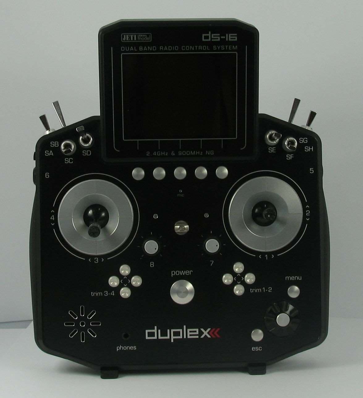
ONTJETIDS16G2US
Apr 12, 2021Receiver/transmitter for radio control model toys
Equipment Class
DSS - Part 15 Spread Spectrum Transmitter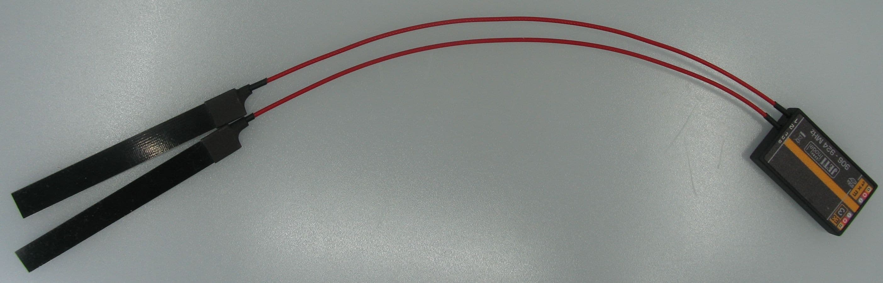
ONTJETIR900NGUS
Feb 22, 2021Receiver/transmitter for radio control model toys
Equipment Class
DSS - Part 15 Spread Spectrum Transmitter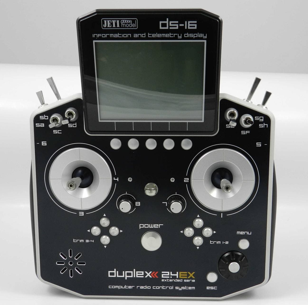
ONTJETIDS16US
Apr 01, 2013Receiver/Transmitter for Radio Control Model Toys
Equipment Class
DSS - Part 15 Spread Spectrum Transmitter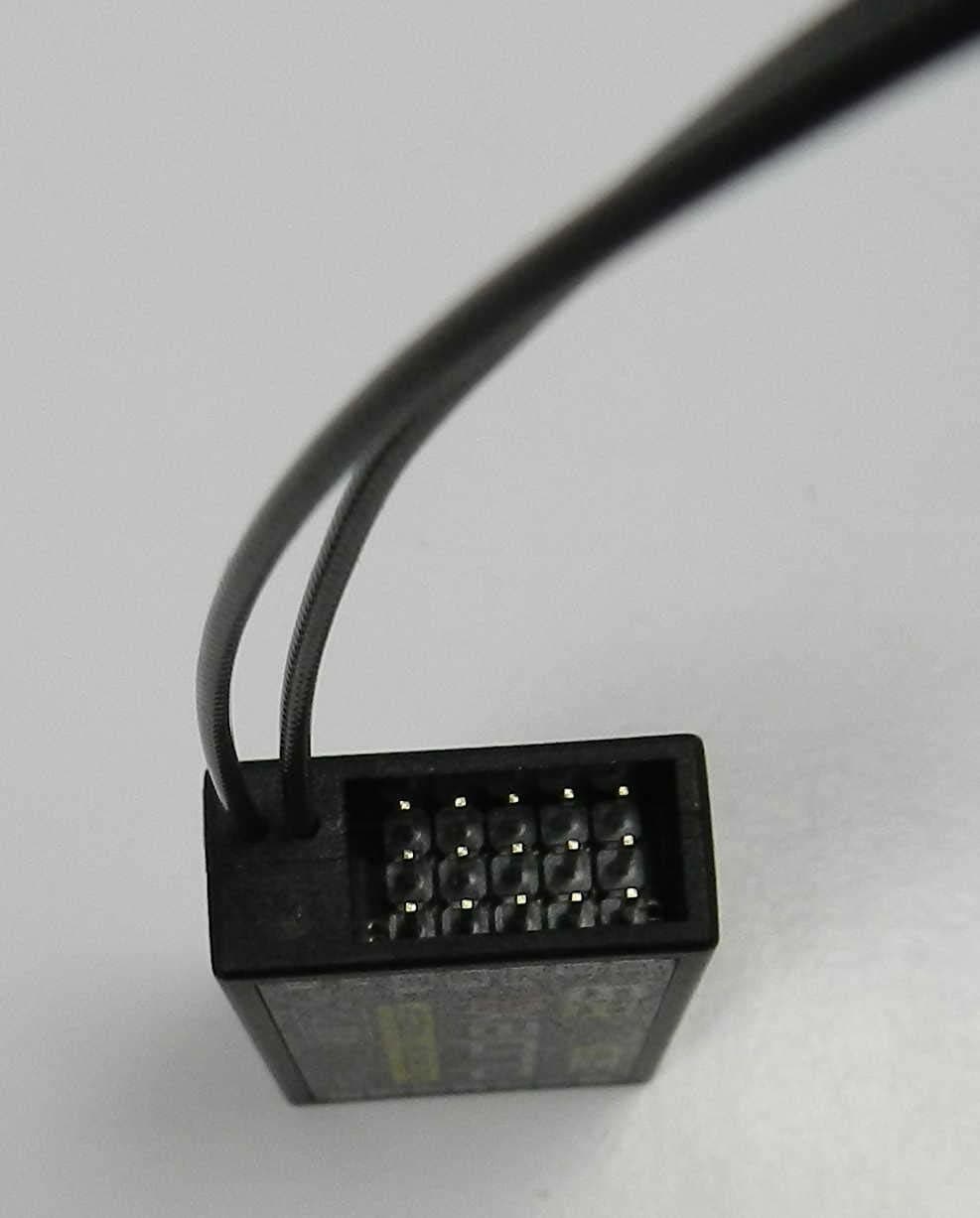
ONTJETIR11EPCUS
Dec 09, 2012Receiver/transmitter for radio control model toys
Equipment Class
DSS - Part 15 Spread Spectrum Transmitter
ONTJETIDC16US
Nov 29, 2012Receiver/Transmitter for Radio Control Model Toys
Equipment Class
DSS - Part 15 Spread Spectrum Transmitter