OOB2018WIRELESS CALL PENDANT
Inter Page Limited Partnership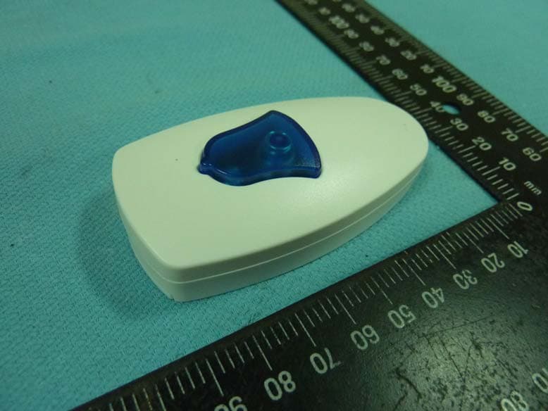
Click to zoom
Application Details
- Equipment Class
- DSC - Part 15 Security/Remote Control Transmitter
- Date of Grant
- Aug 25, 2010
- Application Purpose
- Original Equipment
- Date of Application
- Aug 25, 2010
- Equipment Note
- WIRELESS CALL PENDANT
- Frequency Range
- 433.92000000 - 433.92000000
- Country
- United States
Documents & Files
Document Text
Text extracted from the exhibit documents filed with the FCC. Open a document above to read the original.
Users Manual
1 Pendant IPLP Item No. 2018 Operation Manual Wireless Devices Inc. (Taiwan) 2 The Port item #2018 able transmitter is designed to directly page the nurses or health care persons with a single “Bell button” depressing. No need to dial telephone to get the helps. And the installation is simple without any wires connections. Also, the operation is easy to access the quick emergency aids. Calling Nurse for helps? You can simply just by pressing the “Bell” button. 3 Specifications Mode No. 2018 Paging format: POCSAG Frequency:: 430~470MHz. 1 Channel Crystal controller. Baud rate: 512bps / 1200bps / 2400bps. Message: Numeric and Alphanumeric (Max 40 Character). Message data: Numeric or Alphanumeric. RF output <4 mW (+6.0 db). Modulation: FSK ,NRZ. Deviation: 4.5Khz. Stability: ±10 ppm. Pager Capacity: 1 Button Battery: Type 23A 9V Alkaline battery. Battery life about 240 days ( 3 Time per day). Programming I/O: via USB with P/C. Size: 80mm X 42mm X 18mm. Housing Color: White (other desired colors in minimum 500PCs per order). Model Weight: 34gs (with battery). 4 A. How to program the Item #2108 1). Open the Item #2018 battery cover and take out battery 5 2). Insert the USB programming cable into the item #2018 set 3).Connected USB cable to P/C or N/B computer 4).Install the programming CD software on your P/C or N/B computer 5).Click [WCP2.00] icon to run the Item #2108 programming AP 6 a. Pager No.: Reference Key number of the total 16 message inputs 01 for Bell button message out contents, 02 for magnet switch 2 (*option part no. 820-02), 03 for magnet switch 3 (*option part no. 820-03) 04~16 for other item usages. b. Capcode : This is for 7 digits address use. And it must be same as the used receiving pager. c. Type : Numeric or Alphanumeric Please set the same message type with your used numeric or alphanumeric pager. d. Message This is for the pre-programmed messages to be send out to receiving pagers. e. Date rate This should also be set on the same speed rate with the used pagers. And the baud rate is in POCSAG 512bps or 1200bps or 2400bps type only. f. Preamble Please set this function at the 1000 bits above. And it might not work properly if under the 576 bits. g. Repeater This is for the same 1-4 times repeat message set-up with a single Red button depressing. h. Read Reading the programmed data from your item #2018 i. Write Writing the programming data to your item #2018 7 B. How to insert a necklace hanger string into Item #2018 1. Use the screwdriver to open the rear case first. Then insert the necklace hanger string thru the side case hole as shown on the above picture. 8 2. Put the string thru the case side hole and place on the case holding post. 3. Carefully close the case and put the screen back on. 9 4. Plug in both strings’ conjunction connectors and ready to use it. 10 Part List of item #2018 10mw 430.~470.0MHz Item Part No. Description Size Q'ty 1 U1 HT-7550-1 SOT-89 1 2 U2 HT-7044A-1 SOT-89 1 3 U3 WDIT FC47 SOP24 1 4 U4 93C66 SOT-89 1 5 Y1 6MHZ X'tal 49US 1 6 X1 74mhZ UM-1 1 7 Q1,2,3 MRF6612-24-25 SOT23 3 8 Q6 2N4403 SOT23 2 9 Q5,Q7 2N3904 SOT23 1 10 11 D0,1 IN4148 SMD 1008 2 12 D2 IS5603 SMD 0805 1 13 D3,4,5,6,7,8 MA118 SOD323 6 14 15 VC1 10P 3 x 5 mm SMD 1 16 VR1 10K ohm 3mm SMD 1 17 18 C3 OR SMD 0603 1 19 C4 36P NP0 SMD 0603 1 20 C5,12,15,20 102 SMD 0603 4 21 C6,7,26,CY 22P NP0 SMD 0603 4 22 C8 47P NP0 SMD 0603 1 23 C9,10,11,16,17,19,27 51P NP0 SMD 0603 7 24 C13 13P NP0 SMD 0603 1 25 C14,18,21, 22P NP0 SMD 0603 3 26 27 C22,31,33 103 SMD 0603 3 28 C22A,23,24 NC 11 29 C25 6P NP0 SMD 0603 1 30 C30,32 105 Y5V SMD 0805 2 31 CX NC 32 33 R0 4.7K SMD 0603 1 34 R1,3,20,21,22,23 10K SMD 0603 6 35 R2 1K SMD 0603 1 36 R4 100R ohm SMD 0603 1 37 R15,16,17 100K SMD 0603 3 38 R5,6,9, 22K SMD 0603 3 39 R7,8 220R SMD 0603 2 40 R10 12K SMD 0603 1 41 R11,12 470R SMD 0603 2 42 R18 33K SMD 0603 1 43 R19 2.2K or 2K SMD 0603 1 44 45 46 L1 680nH SMD 1008 1 47 L2,4,5,6,8,9 91nH SMD 0603 6 48 L3 630nH SMD 1008 1 49 L7 12nH SMD 0603 1 50 L10,11 56nH SMD 0805 2 51 52 SW1 6mm X 6MM X 8H DIP4 1 53 J1 1.27mm 180D X 4P 1.27X4P 1 55 LED1 5mm RED+BLUE HL DIP 5mm3P 1 56 PCB1 M-820 2L 2L 1.0mm 1 12 Part No. and location on PCB. FCC ID: OOB2018 FCC Compliance and Advisory Statement This device complies with Part 15 of the FCC rules. Operation is subject to the following two conditions:(1) this device may not cause harmful interference, and (2) this device must accept any interference received, including interference that may cause undesired operation. This equipment has been tested and found to comply with the limits for a Class B digital device, according to Part 15 of the FCC rules. These limits are designed to provide reasonable protection against harmful interference in a residential installation. This equipment generates, uses and can radiate radio frequency energy and if not installed and used in accordance with the instructions, may cause harmful interference to radio communications. However, there is no guarantee that interference will not occur in a particular installation. If this equipment does cause harmful interference to radio or television reception, which can be determined by turning the equipment off and on, the user is encouraged to try correct the interference by one or more of the following measures: 1.Reorient the receiving antenna. 2.Increase the separation between the equipment and receiver. 3.Connect the equipment into and outlet on a circuit different from that to which the receiver is connected. 4.Consult the dealer or an experienced radio/TV technician for help. Any special accessories needed for compliance must be specified in the instruction manual. Warning: A shielded-type power cord is required in order to meet FCC emission limits and also to prevent interference to the nearby radio and television reception. It is essential that only the supplied power cord be used. Use only shielded cables to connect I/O devices to this equipment. CAUSION: Any changes or modifications not …
Text truncated - open the document above for the full version.
Block Diagram
Item # 2018 Pendant Block Diagram Wireless devices Inc. (Taiwan) 20100625 USB interface 5V Regulator 9V Battery Low battery check CPU & Encoder EEPROM FSK Transmitter Low Pass FilterCrystal controller & On Air ind Battery low ind Antenna VR1 Modulation adj VC1 Frequency fine adj SW1 Buzzer Clock Clock 6MHz Y1 CRYSTALX1 76.258333 MHz
External Photos
Spectrum Research & Testing Lab., Inc. No. 101-10, Ling 8, Shan-Tong Li, Chung-Li City, Taoyuan, Taiwan, R.O.C. Reference No.: A10053102 Photo Page: 1 of 3 PHOTOS OF EUT
ID Label/Location Info
Spectrum Research & Testing Lab., Inc. No. 101-10, Ling 8, Shan-Tong Li, Chung-Li City, Taoyuan, Taiwan, R.O.C. Sample of FCC ID Label The device is so small that the 2 parts warning statement does not have to go on the device. It will be really hard to read. We remove the 2 parts statement from the device since we already have it in the manual. FCC ID : OOB2018
Internal Photos
Spectrum Research & Testing Lab., Inc. No. 101-10, Ling 8, Shan-Tong Li, Chung-Li City, Taoyuan, Taiwan, R.O.C. Reference No.: A10053102 Photo Page: 2 of 3 PHOTOS OF EUT Spectrum Research & Testing Lab., Inc. No. 101-10, Ling 8, Shan-Tong Li, Chung-Li City, Taoyuan, Taiwan, R.O.C. Reference No.: A10053102 Photo Page: 3 of 3 PHOTOS OF EUT
Operational Description
FCC ID: OOB2018 Operational Description of the equipment 1). Open the Item #2018 battery cover and take out battery. 2). Insert the USB programming cable into the item #2018 set. 3).Connected USB cable to P/C or N/B computer. 4).Install the programming CD software on your P/C or N/B computer 5).Click [WCP2.00] icon to run the Item #2108 programming AP. a. Pager No.: Reference Key number of the total 16 message inputs 01 for Bell button message out contents, 02 for magnet switch 2 (*option part no. 820-02), 03 for magnet switch 3 (*option part no. 820-03) 04~16 for other item usages. b. Capcode : This is for 7 digits address use. And it must be same as the used receiving pager. c. Type : Numeric or Alphanumeric Please set the same message type with your used numeric or alphanumeric pager. d. Message This is for the pre-programmed messages to be send out to receiving pagers. e. Date rate This should also be set on the same speed rate with the used pagers. And the baud rate is in POCSAG 512bps or 1200bps or 2400bps type only. f. Preamble Please set this function at the 1000 bits above. And it might not work properly if under the 576 bits. g. Repeater This is for the same 1-4 times repeat message set-up with a single Red button depressing. h. Read Reading the programmed data from your item #2018 i. Write Writing the programming data to your item #2018 Frequency Band UHF Band 430-470 MHz Carrier Frequency 433.92 MHz Number of Channel 1 RF Output Power 4mW Modulation Type FSK I.F. & L.O. I.F. : None ; L.O. : 72.320 MHz Duty Cycle 10 % Mode of operation Simplex Bit Rate of Transmission 512 or 1200 or 2400 bps Antenna Type NA Antenna Gain NA Operating Temperature Range 0 ~ 50 o C
Operational Description
TECHNOLOGICAL SPEC. 1. Product Name: Wireless Call Pendant Model: 2018 Brand: INTER PAGE 2. Power Source: ■ DC 9 V, 0.1 A; □ AC V, A 3. Frequency Band: UHF Band 430-470 MHz Carrier Frequency: 433.920 MHz 4. Number of Channel: 1 5. Channel Spacing: 12.5KHz/25KHz 6. RF Output Power (ERP or EIRP) : 6 dBm = 4m W 7. I.F.: non MHz; L.O.: 72.32 MHz 8. Modulation Type: FSK 9. Duty Cycle: 10 % 10. Mode of operation (duplex, simplex, half duplex) : Simplex 11. Bit Rate of Transmission: 512 or 1200 or 2400 bps 12. Antenna Type: NA 13. Antenna gain: dBi 14. Operating Temperature Range: 0 ~ 50 °C 15. Channel bandwidth : 0.025 MHZ
Schematics
Q1 Antenna CX VC1 C7 Q2 C8 C9 C5 C15 C12 Q3 C16 C24 D2 VR1 R2 R3 R4R9 R7 C4 C6 L2 L1 L3 L6 L4 L5 C11 C10 C13 C14 R1 R22 R11 Item # 2018 Pendant C30 R5 TX Ind Y1 PTT 1 -DATA OUT 2 +DATA OUT 3 XIN 12 XOUT 13 OUT 1 5 OUT 2 20 OUT 3 6 OUT 4 19 SEL 11 D- 15 D+ 16 IN 1 7 IN 2 18 IN 3 8 Mode 4 IN 4 17 VSS 9 VCC 14 DO 22 DI 23 SK 21 CS 24 TEST 10 U3 USB CONTROLLER FC47 R20 Wireless devices Inc. (Taiwan) 1 2 3 4 To USB J1 R19 R18 V+ GND D+ D- R15,16,17 R25 R21 CY D3~D4 CS 1 CK 2 DI 3 DO 4 VCC 8 NC 7 ORG 6 GND 5 93LC46 A type Q6 Q8 Q7 R23 R21 R28 LED1 2/2 LED1 2/2 Battery Lo Ind C20 C31 20100622 VI G 5VVI G LO 7050-17044-1 BZ1 Buzzer PTT2&Buzzer BT1 A23 9V 1AD5 X1 SW1 U4 U1U2 D1 D0 L11 C27C23 C19C17 L10 L8 C18 R8 R6 TP1 C33C32 Band Pass Filter
Test Report
Spectrum Research & Testing Lab., Inc. No. 101-10, Ling 8, Shan-Tong Li, Chung-Li City, Taoyuan, Taiwan TEST REPORT Reference No.: A10070606 Report No.: FCCA10070606 FCCID: OOB2018 Page:2 of 21 Date :Jul. 26, 2010 TABLE OF CONTENTS 1. DOCUMENT POLICY AND TEST STATEMENT....................................................... 3 1.1 DOCUMENT POLICY ............................................................................................. 3 1.2 TEST STATEMENT ................................................................................................ 3 1.3 EUT MODIFICATION.............................................................................................. 3 2. DESCRIPTION OF EUT AND TEST MODE ........................................................... 4 2.1 GENERAL DESCRIPTION OF EUT ....................................................................... 4 2.2 DESCRIPTION OF SUPPORT UNIT...................................................................... 4 2.3 DESCRIPTION OF TEST MODE ........................................................................... 5 3 DESCRIPTION OF APPLIED STANDARDS............................................................ 5 4. CONDUCTED EMISSION TEST ............................................................................ 5 5 20dB BANDWIDTH.................................................................................................... 6 5.1 LIMIT ......................................................................................................................6 5.2 TEST EQUIPMENT ................................................................................................ 6 5.3 TEST SET-UP......................................................................................................... 6 5.4 TEST PROCEDURE............................................................................................... 6 5.5 EUT OPERATING CONDITION.............................................................................. 6 5.6 TEST RESULT........................................................................................................ 7 6. RELEASE OR OPERATING TIME ........................................................................... 8 6.1 LIMIT ......................................................................................................................8 6.2 TEST EQUIPMENT ................................................................................................ 8 6.3 TEST SET-UP......................................................................................................... 8 6.4 TEST PROCEDURE............................................................................................... 8 6.5 EUT OPERATING CONDITION.............................................................................. 9 6.6 TEST RESULT........................................................................................................ 9 7. FUNDERMENTAL & SPURIOUS RADIATED EMISSION TEST ............................ 10 7.1 LIMIT .................................................................................................................... 10 7.2 TEST EQUIPMENT ...............................................................................................11 7.3 TEST SET-UP....................................................................................................... 12 7.4 TEST PROCEDURE............................................................................................. 14 7.5 EUT OPERATING CONDITION............................................................................ 14 7.6 TEST RESULT...................................................................................................... 15 8. PHOTOS OF TESTING ........................................................................................ 19 9. TERMS OF ABBREVIATION .................................................................................. 21 Spectrum Research & Testing Lab., Inc. No. 101-10, Ling 8, Shan-Tong Li, Chung-Li City, Taoyuan, Taiwan TEST REPORT Reference No.: A10070606 Report No.: FCCA10070606 FCCID: OOB2018 Page:3 of 21 Date :Jul. 26, 2010 1. DOCUMENT POLICY AND TEST STATEMENT 1.1 DOCUMENT POLICY - The report shall not be reproduced except in full, without the written approval of SRT Lab, Inc. - The report must not be used by the client to claim product certification, approval, or endorsement by NVLAP, NIST, or any agency of the Federal Government. 1.2 TEST STATEMENT - The test results in the report apply only to the unit tested by SRT Lab. - There was no deviation from the requirements of test standards during the test. - DC power source, 9 VDC, was used during the test. 1.3 EUT MODIFICATION - Serial R180 between X1 and R5 - Remove ANT,L4 - R4 change to 180 - R7,R8 change to 150 - ANT add in 51pf to ground Spectrum Research & Testing Lab., Inc. No. 101-10, Ling 8, Shan-Tong Li, Chung-Li City, Taoyuan, Taiwan TEST REPORT Reference No.: A10070606 Report No.: FCCA10070606 FCCID: OOB2018 Page:4 of 21 Date :Jul. 26, 2010 2. DESCRIPTION OF EUT AND TEST MODE 2.1 GENERAL DESCRIPTION OF EUT Product Wireless Call Pendant Model NO. 2018 Power Supply DC 9V / 0.1A Frequency Band UHF Band 430-470 MHz Carrier Frequency 433.92 MHz Number of Channel 1 RF Output Power 4mW Modulation Type FSK I.F. & L.O. I.F. : None ; L.O. : 72.320 MHz Duty Cycle 10 % Mode of operation Simplex Bit Rate of Transmission 512 or 1200 or 2400 bps Antenna Type NA Antenna Gain NA Operating Temperature Range 0 ~ 50 o C NOTE: 1. For more detailed information, please refer to the EUT’s specification or user’s manual provided by manufacturer. 2.2 DESCRIPTION OF SUPPORT UNIT The transmitter part of EUT was tested along and configured by the requirement of ANSI C63.4. All interface ports were connected to the appropriate support units via specific cables. The support units and cables are listed below. No Device Brand Model # FCC ID/DoC Cable N/A NOTE : For the actu…
Text truncated - open the document above for the full version.
Test Setup Photos
Spectrum Research & Testing Lab., Inc. No. 101-10, Ling 8, Shan-Tong Li, Chung-Li City, Taoyuan, Taiwan TEST REPORT Reference No.: A10070606 Report No.: FCCA10070606 FCCID: OOB2018 Page:19 of 21 Date :Jul. 26, 2010 8. PHOTOS OF TESTING Radiated test : below 1GHz Spectrum Research & Testing Lab., Inc. No. 101-10, Ling 8, Shan-Tong Li, Chung-Li City, Taoyuan, Taiwan TEST REPORT Reference No.: A10070606 Report No.: FCCA10070606 FCCID: OOB2018 Page:20 of 21 Date :Jul. 26, 2010 Radiated test : above 1GHz
Contact Information
Applicant
Christel A. Coffin(Office Manager/Bookkeeper)
Test Firm
Spectrum Research & Testing Laboratory, IncJohnson Ho
Technical Specifications
| # | Rule Parts | Frequency Range | Power Output |
|---|---|---|---|
| 1 | 15.231 | 433.92 MHz - 433.92 MHz | - |