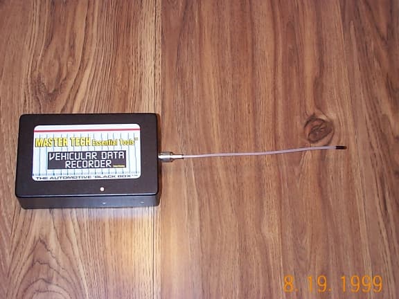
Click to zoom
Application Details
- Equipment Class
- CRR - Superregenerative Receiver
- Date of Grant
- Oct 25, 1999
- Application Purpose
- Original Equipment
- Date of Application
- Aug 23, 1999
- Frequency Range
- 318.00000000 - 318.00000000
- Country
- United States
Documents & Files
Document Text
Text extracted from the exhibit documents filed with the FCC. Open a document above to read the original.
Users Manual
1 Preliminary Draft MASTER TECH Essential Tools TM Vehicular Data Recorder Installation and Operating Instructions 1- Installation In The Vehicle Determine whether a Custom Interconnect System, appropriate for the vehicle and for the problem being investigated, is available for use. If an appropriate Custom Interconnect System is not available, the Universal Interconnect System must be used. When Using A Custom Interconnect System: 1- Locate the vehicle computer(s) or other electronic device(s) that the Custom Interconnect System is specified for. 2- Disconnect the vehicle wiring harness connector(s) and replace them with the corresponding connector(s) on the Custom Interconnect System. 3- Connect the vehicle wiring harness connector(s) (which were just disconnected from the vehicle electronics) to the corresponding connector(s) on the Custom Interconnect system. 4- When using the optional Fuel Pressure Sensor, connect the sensor assembly to the vehicle fuel system. When the Custom Interconnect System is installed in the engine compartment, connect the fuel pressure Sensor assembly directly to the 4-pin connector on the Custom Interconnect System. When the Custom Interconnect System is installed in the passenger compartment, use the optional Fuel Pressure Extension Cable to connect the Fuel Pressure Sensor assembly to the 4-pin connector on the Custom Interconnect System, routing the extension cable out through the hood cowling and through the door seal into the passenger compartment. 5- Connect the Custom Interconnect System to the Vehicular Data Recorder. When Using the Universal Interconnect System: 1-Identify the signals within the vehicle that are to be monitored. 2- Using the vehicle wiring diagram, identify the connector pins that are to be back-probed. 3- Locate the vehicle connectors that are to be back-probed, carefully insert the appropriate probe pins on the Universal Interconnect System into the desired vehicle connector locations by sliding the probe pin along the vehicle wire and into the vehicle connector housing, so that the probe pin is touching the contact inside the vehicle connector housing. 4-When using the optional Fuel Pressure Sensor, connect the sensor assembly to the vehicle fuel system. When the Universal Interconnect System is installed in the engine compartment, connect the Fuel Pressure Sensor assembly directly to the 4-pin connector on the Universal Interconnect System. When the Universal Interconnect System is installed in the passenger compartment, use the optional Fuel Pressure Extension Cable to connect the fuel Pressure Sensor assembly to the 4- pin connector on the Universal Interconnect System, routing the extension cable out through the hood cowling and through the door seal into the passenger compartment. 5- Connect the Universal Interconnect System to the Vehicular Data Recorder. 2 6- Place the Vehicular Data Recorder in a secure location close to the installed Interconnect System. When the installation is in the engine compartment, keep the recorder and cabling as far as possible from metal surfaces that will become extremely hot! Whenever possible, place the recorder in a location that will cause air to flow over the recorder. When the installation is in the passenger compartment, keep the recorder and cabling away from passengers, preferably placing them up inside the hush panel. 7- Position the wire antenna on the Vehicular Data Recorder so that it forms the top of a letter "T" on an imaginary line drawn from the vehicle steering wheel, while not allowing the antenna wire to come in direct contact with any metal surface. 8- Install the Wireless Pushbutton on the vehicle steering wheel, using the attached hook-and-loop fastener strip. The Wireless Pushbutton should be positioned on an area of the steering wheel that the driver would normally grip, with the plastic case toward the inside of the steering wheel. This ensures that the pushbutton is close to the driver's hand, while not interfering with movement of the hand on the steering wheel. 2-Operation In the Vehicle The vehicle should be operated normally, with the following exception. In the event that the Vehicular Data Recorder is being used to troubleshoot a starting problem, the ignition should be ON for approximately 30 seconds before attempting to start the vehicle, to allow time for the Vehicular Data Recorder to initialize and start the recording process. While the vehicle is being operated with the Vehicular Data Recorder installed and functioning, the "Check Engine" light will flash briefly at 4 second intervals. In the event that the vehicle stalls or the "Check Engine" light activates, the driver does not have to press the Wireless Pushbutton on the steering wheel - the data recorder will automatically record the event. In the event that a problem occurs that does not result in a stall or in activation of the "Check Engine" light, the vehicle operator should press the Wireless Pushbutton within 20 seconds, holding it pressed for approximately 1 second, to record the event. The "Check Engine" light will rapidly (3 times per second) flash on-and-off to indicate that the event has been recorded. When one or more events have been recorded (due to a vehicle stall and/or the operator has pressed the Wireless Pushbutton) or the "Check Engine" light is remaining on steady, the vehicle should be returned to the automotive technician as soon as possible to have the problem identified and corrected. 6- Retrieving and Viewing Recorded Event Data Recorded event data can be retrieved from the Vehicular Data Recorder while the recorder is installed in a vehicle, or the recorder can be removed and taken to a more convenient location. When data is to be retrieved from the recorder while the recorder is installed in a vehicle, connect a 9-pin serial null-modem cable from the 9-pin D-sub connector on the Vehicular Data Recorder to a pc-compatible computer (usually a lap-top when the recorder is in…
Text truncated - open the document above for the full version.
Block Diagram
Power Supply 12 V DC in 5 V DC out RF Pre-amp Superregen Oscillator Quench Oscillator Amplifier Open-Collector Ouptut Switch Microcontroller 4.005 MHz Ceramic Resonator Ant 65 kHz R/C Circuit 318 MHz L/C Tank Output +12V Ground +5V Master Tech Engineering, Inc. Block Diagram of Superregererative Receiver in the MASTER TECH Essential Tools (tm) Vehicular Data Recorder
ID Label/Location Info
Label Placement on Device (on side opposite Product Label) Facsimile of FCC Label (Shown Actual Size – 3.5” x 2”) FCC ID: OOI VDR1 -------------------------------
Internal Photos
Internal Photographs Included in Test Report FCC07099
Operational Description
Page 1 of 1 Master Tech Engineering, Inc. Technical Description of Superregenerative Receiver in the MASTER TECH Essential Tools ™ Vehicular Data Recorder The MASTER TECH Essential Tools ™ Vehicular Data Recorder is a piece of commercial test equipment for use in motor vehicles, for the purpose of recording and identifying electronic malfunctions within the motor vehicle. Due to its use in motor vehicles and as commercial test equipment, the digital device within the Vehicular Data Recorder is an exempted device per 15.103(a) and 15.103(c) respectively. The superregenerative receiver is installed in the Vehicular Data Recorder to provide wireless control of the recording process, when used in conjunction with the MODEL ACT-21 transmitter from LINEAR CORPORATION (FCC ID: EF4 DNT00057), which is an amplitude modulated garage-door-type transmitter operating at 318 MHz. An external antenna (9 inch wire antenna is supplied with the receiver) is coupled to the RF pre- amp, which provides amplification and isolates the antenna from the superregen oscillator. This isolation serves to minimize loading of the oscillator as the antenna impedance varies – primarily due to changes in the proximity to metal surfaces, and to minimize the amount of superregen oscillator energy that is coupled to the antenna. The signal at the output of the RF pre-amp is coupled to the superregen oscillator, which is free-running at or close to the operating frequency of 318 MHz. The quench oscillator, which operates at approximately 65 kHz, is also coupled to the superregen oscillator, and acts to power the free-running oscillator on and off at an approximately 65 kHz rate. With an applied RF signal from the RF pre-amp, the superregen oscillator reaches its equilibrium amplitude sooner than it does on thermal noise alone. The effect of the applied RF signal is to increase the average area under the RF envelope according to the level of the applied signal. The output from the superregen oscillator is applied to an amplifier to boost its level and square up the signal, and the output of the amplifier is coupled to a microcontroller. The microcontroller, which contains an internal clock oscillator controlled by an external 4.005 MHz resonator) performs the demodulation of the RF signal by pulse-width demodulation, as well as performing the decoding function by comparing the received data with one or more stored “activation codes”. When a demodulated data structure matches a stored “activation code”, the microcontroller briefly activates an open-collector switch, causing the receiver output to be forced to ground, which triggers the recording function of the Vehicular Data Recorder. The receiver ground connects to a metal box at the power ground input and at the antenna connector, and the receiver is encased within a metal shield. Thus, the metal box/shield serves as ground for the receiver circuit and as the ground reference for the antenna. The supplied antenna is a 9 inch (approximately ¼ wavelength at 318 MHz) wire antenna, which couples to a TNC connector attached to the receiver box. The TNC connector allows for user replacement of the antenna in the event that the antenna is damaged.
Test Setup Photos
Test Setup Photographs Included in Test Report FCC07099
Contact Information
Applicant
Robert P Cooper(President)
Test Firm
IQS, a Division of Degree ControlsGaby Abboud
Technical Specifications
| # | Rule Parts | Frequency Range | Power Output | Emission |
|---|---|---|---|---|
| 1 | 15B | 318 MHz - 318 MHz | - | N/A |