OOLUKL60104Base Station Transceiver LMDS Service
Ericsson Microwave Systems AB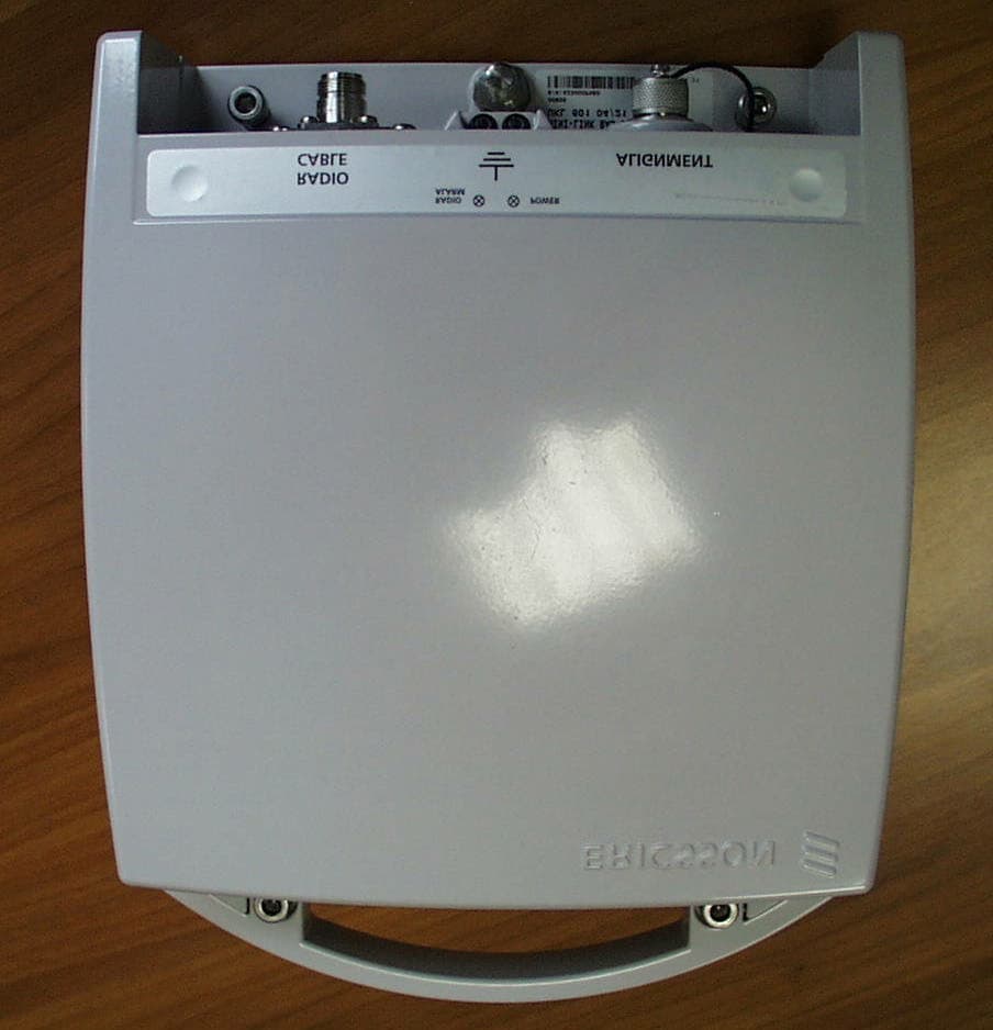
Click to zoom
Application Details
- Equipment Class
- TNB - Licensed Non-Broadcast Station Transmitter
- Date of Grant
- Mar 18, 2001
- Application Purpose
- Original Equipment
- Date of Application
- Dec 18, 2000
- Equipment Note
- Base Station Transceiver LMDS Service
- Frequency Range
- 31000.00000000 - 31300.00000000
- Country
- United States
Documents & Files
Document Text
Text extracted from the exhibit documents filed with the FCC. Open a document above to read the original.
Users Manual
MINI-LINK BAS Technical Description Ericsson is the leading provider in the new telecom world, with communications solutions that combine telecom and datacom technologies with freedom of mobility for the user. With more than 100,000 employees in 140 countries, Ericsson simplifies communications for its Customers - network operators, service providers, enterprises and consumers - the world over. Ericsson Information on Demand Database can be addressed at: http://www.ericsson.com We continuously develop and improve our products and therefore reserve the right to alter technical details without notice. Ericsson Microwave Systems AB Microwave Radio Division S-431 84 Mölndal SWEDEN Telephone: +46 31 747 00 00 Fax: +46 31 27 72 25 EN/LZB 111 0542 P2B © Ericsson Microwave Systems AB 2000 Designed and developed by Ericsson Lab Italy R&D Global Product Center via Cadorna 73, 20090 Vimodrone, Milan ITALY 1MINI-LINK BAS EN/LZB 111 0542 P2BTechnical Description MINI-LINK BAS Technical Description Copyright Ericsson 2000 MINI-LINK BAS2 Technical DescriptionEN/LZB 111 0542 P2B Foreword The customer documentation includes all information and documents necessary for a basic knowledge of Ericsson systems. The above said documentation has its own code number and release; the latter is subject to changes whenever eventual updates may occur. The customer documentation is subdivided into the following manuals: • AT Installation Manual • Installation Manual • Operation and Maintenance Manual • Planning and Engineering Manual • Product Catalogue • Technical Description The purpose of this description is to support the reader with detailed information on the product from technical and functional points of view. It supplies all information necessary to understand equipment operation and technical characteristics. This document is addressed to the network planner and operation personnel who will find the information they are interested in. Use of any trademark in this document is not intended in any way to infringe on the rights of the trademark holder. 3MINI-LINK BAS EN/LZB 111 0542 P2BTechnical Description Preface For more information, please refer to the MINI-LINK BAS Product Catalogue. You may also contact your Ericsson representative or the area sales manager for your country at: Ericsson Microwave Systems AB Microwave Radio Division S-431 84 Mölndal SWEDEN Telephone: +46 31 747 00 00 Fax: +46 31 27 72 25 Please contact your Ericsson representative for latest details and data. The specifications or configuration contained in this document are subject to change without notice due to continuous design improvement. If there is any conflict between this document and Compliance statements, the latter will supersede this document. Please refer to the “Information Revision” document for details about the updating level of the present description. The MINI-LINK BAS and the relative Customer documentation have been designed and developed by: Ericsson Lab Italy R&D Global Product Center via Cadorna 73 20090 Vimodrone Milan ITALY. MINI-LINK BAS4 Technical DescriptionEN/LZB 111 0542 P2B Contents 1Introduction ............................. 1-1 1.1General Information .................................. 1-2 1.2Manual Structure....................................... 1-2 1.3General Overview ..................................... 1-3 1.3.1Opportunities..................................................... 1-3 1.3.2Product Benefits................................................ 1-4 1.4Terminology .............................................. 1-6 2System Description ................ 2-1 2.1Overview................................................... 2-2 2.2System Components................................. 2-4 2.2.1AT ..................................................................... 2-5 2.2.1.1FlexNU ................................................................2-6 2.2.1.2ODU ....................................................................2-6 2.2.1.3ACT .....................................................................2-6 2.2.2RN ..................................................................... 2-6 2.2.2.1R-AAS .................................................................2-8 2.2.2.2ODU ..................................................................2-10 2.2.3C-AAS ............................................................. 2-11 2.2.4Control and Management................................ 2-11 2.2.4.1CP .....................................................................2-11 2.2.4.2EM.....................................................................2-11 2.3Configuration Limits ................................ 2-12 2.4System Interfaces ................................... 2-12 2.4.1Intra-System Interfaces ................................... 2-12 2.4.2Customer Service Interfaces ........................... 2-13 2.4.3Local Exchange/ISP Interfaces ....................... 2-14 3Network Architecture.............. 3-1 3.1Introduction ............................................... 3-2 3.2SN............................................................. 3-3 3.2.1SN R-AAS Stand-alone ..................................... 3-3 3.2.2SN C-AAS ......................................................... 3-4 3.2.3Generic MINI-LINK BAS Network...................... 3-6 3.2.4SN connection to CP and EM............................ 3-7 3.2.5Examples of an Overall Network ....................... 3-8 3.3System Synchronisation ........................... 3-9 3.4Traffic Routing ........................................ 3-10 5MINI-LINK BAS EN/LZB 111 0542 P2BTechnical Description 3.5Typical Network Applications...................3-11 4End-User Services................... 4-1 4.1Introduction ...............................................4-2 4.2Data Communication.................................4-3 4.2.1Ethernet Frames Encapsulation According to RFC 1483 ......................................................4-4 4.3CE Services .......…
Text truncated - open the document above for the full version.
Attestation Statements
Applicant: FCC ID: Ericsson Microwave Systems AB OOLUKL60104 CERTIFICATION OF DATA The technical data contained in this application has been taken personally or under my supervision and is certified true and correct. My relevant qualifications are: Graduated in Telecommunication Engineering, Rome University Nine years experience in design and testing of analog/digital communication equipment with Ericsson Rome, Italy Ten years experience as Line Manager for Hardware and Firmware Technological Unit in Ericsson Rome, Italy. One year as Product Unit Manager for Microwave Access Product in Ericsson, Italy NAME: Alessandro Giacalone POSITION:Local Executive Officer Product Unit Manager Wireless Broadband Access DATE:02 October 2000 © 2000 Ericsson Microwave System AB
Cover Letter(s)
December 19, 2000 Federal Communications Commission Authorization & Evaluation Division 7435 Oakland Mills Road Columbia, Maryland 21046 Attention: Equipment Authorization Branch Subject:Type Acceptance for FCC ID: OOLUKL60104 Gentlemen, Ericsson Microwave Systems AB requests a grant of Certification for the above mentioned FCC Identifier. This base station is designed for use in part 101 Fixed Microwave Service, Subpart L - Local Multipoint Distribution Service. The base station operates in the 31.0 to 31.3 GHz range. Ericsson Microwave System AB requests confidentiality under 47 CFR 0.459 for the following exhibits listed: Exhibit 4 Block Diagrams Exhibit 5 Circuit Diagrams Exhibit 12 Operational Description Exhibits 4, 5 and 12 are marked CONFIDENTIAL on the electronic filing submission. Justification of this request for confidentiality is to protect Ericsson’s competitive advantage on the design of this base station and the unique methods employed in the RF design of this unit. To protect Ericsson’s competitive advantage on these proprietary techniques, we request the above listed exhibits be held as confidential and withheld from the Public Information File. Sincerely, John P. Rothgeb Regulatory Services Lynchburg, VA 24502 Tel: (804) 592-7476 Fax: (804) 592-6510 [email protected]
ID Label/Location Info
Open INSTRUCTION 1(2) Prepared (also subject responsible if other) No. EMW/SP/MLT Lennart Johansson +46 33 1797089708 151 86-1/CSU 105 20Uen Approved Checked Date Rev Reference EMW/SP/MLC (Lennart Persson) 2000-11-04 PN1 4.6 Market marking The unit shall marks with label LZF 401 1079. FCC ID: OOLUKL60104 Table 7 UKL 601 03 FCC ID: OOLUKL60103 UKL 601 04 FCC ID: OOLUKL60104 4.6.1 Positioning FCC ID: OOLUKL60104 Open INSTRUCTION 2(2) Prepared (also subject responsible if other) No. EMW/SP/MLT Lennart Johansson +46 33 1797089708 151 86-1/CSU 105 20Uen Approved Checked Date Rev Reference EMW/SP/MLC (Lennart Persson) 2000-11-04 PN1 2.4 Positioning
Parts List/Tune Up Info
Applicant:FCC ID: Ericsson Microwave Systems AB OOLULKL60104 © 2000 Ericsson Microwave Systems AB Exhibit 10 ALIGNMENT PROCEDURE Alignment Procedure All the necessary adjustments are set in the factory and will need no further adjustments in the field. (Oscillators, waveguide filters are tuned to the right frequencies, Tx amplifier are set and verified not exceed maximum output levels, etc.) Actual channel frequency as well actual transmitter output power are selected, through software, during installation and commisioning. If a failure occurs, causing for instance the RF oscillator to go out of phase-lock, the transmitter will automatically shut down. 10-1MINI-LINK BAS EN/LZB 111 0542 P2BTechnical Description Technical Data MINI-LINK BAS10-2 Technical DescriptionEN/LZB 111 0542 P2B 10.1 System Parameters The MINI-LINK BAS operates with the following high frequency parameters. 10.1.1 Frequency Range The following channel spacing feature is available: 28 MHz for 37.5 Mbps. The RAU is available for different frequency channel arrangements, according to FCC, ITU-R and ETSI recommendations. The MINI-LINK BAS frequency bands are listed below. Frequency bands (GHz) Frequency range (GHz) Duplex distance (MHz) Channel spacing (MHz) ETSI 26 GHz24.5-26.5100828 LMDS "A" 28 GHz27.5-28.3542028 LMDS “B” 31 GHz31,0-31,3022528 ETSI 26 GHz frequency plan, related to CEPT rec. TR 13-02 Channel numberDuplex (MHz)Downlink TxUplink Tx 1100824.563 GHz25.571 GHz 2100824.591 GHz25.599 GHz 3100824.619 GHz25.627 GHz 4100824.647 GHz25.655 GHz 5100824.675 GHz25.683 GHz 6100824.703 GHz25.711 GHz 7100824.731 GHz25.739 GHz 8100824.759 GHz25.767 GHz 9100824.787 GHz25.795 GHz 10100824.815 GHz25.823 GHz 11100824.843 GHz25.851 GHz 12100824.871 GHz25.879 GHz 13100824.899 GHz25.907 GHz 14100824.927 GHz25.935 GHz 15100824.955 GHz25.963 GHz 10-3MINI-LINK BAS EN/LZB 111 0542 P2BTechnical Description ETSI 26 GHz frequency plan, related to CEPT rec. TR 13-02 Channel numberDuplex (MHz)Downlink TxUplink Tx 16100824.983 GHz25.991 GHz 17100825.011 GHz26.019 GHz 18100825.039 GHz26.047 GHz 19100825.067 GHz26.075 GHz 20100825.095 GHz26.103 GHz 21100825.123 GHz26.131 GHz 22100825.151 GHz26.159 GHz 23100825.179 GHz26.187 GHz 24100825.207 GHz26.215 GHz 25100825.235 GHz26.243 GHz 26100825.263 GHz26.271 GHz 27100825.291 GHz26.299 GHz 28100825.319 GHz26.327 GHz 29100825.347 GHz26.355 GHz 30100825.375 GHz26.383 GHz 31100825.403 GHz26.411 GHz 32100825.431 GHz26.439 GHz MINI-LINK BAS10-4 Technical DescriptionEN/LZB 111 0542 P2B LMDS "A" 28 GHz frequency plan Channel numberDuplex (MHz)Downlink TxUplink Tx 1420 MHz27.519 GHz27.939 GHz 2420 MHz27.547 GHz27.967 GHz 3420 MHz27.575 GHz27.995 GHz 4420 MHz27.603 GHz28.023 GHz 5420 MHz27.631 GHz28.051 GHz 6420 MHz27.659 GHz28.079 GHz 7420 MHz27.687 GHz28.107 GHz 8420 MHz27.715 GHz28.135 GHz 9420 MHz27.743 GHz28.163 GHz 10420 MHz27.771 GHz28.191 GHz 11420 MHz27.799 GHz28.219 GHz 12420 MHz27.827 GHz28.247 GHz 13420 MHz27.855 GHz28.275 GHz 14420 MHz27.883 GHz28.303 GHz 15420 MHz27.911 GHz28.331 GHz LMDS “B” 31 GHz frequency plan Channel numberDuplex (MHz)Downlink TxUplink Tx 1225 MHz31,021 GHz31,251 GHz 2225 MHz31,049 GHz31,279 GHz 10.1.2 Transmitter Performance Transmitter output power has the following typical values with the guaranteed value within parentheses: • 23(21) dBm for ETSI 26 GHz • 23(21) dBm for LMDS "A" 28 GHz • 23(21) dBm for LMDS "B" 31 GHz Note:Filter loss is included. 10-5MINI-LINK BAS EN/LZB 111 0542 P2BTechnical Description Frequency Tolerances The frequency stability is +/- 10 ppm from nominal centre frequency. Both Tx and Rx oscillators (VCO) are phase locked loop controlled. Output Spectrum The transmitter spectrum stays in all operating conditions within the given mask centred at nominal channel frequency. There is also a typical output spectrum reported, see Figure 10–1. f-fo [MHz] 0 10203040506070 0 -10 -20 -30 -40 -50 -60 Spectrum Mask [dBc] Spectrum Mask Typical Output Spectrum Figure 10–1 Transmitter Mask Capacity Power density level (dB)Frequency (MHz) MbpsA0A1A2f1f2f3f4f5 37.50-23-451119254570 MINI-LINK BAS10-6 Technical DescriptionEN/LZB 111 0542 P2B 10.1.3 Receiver Performance Receiver input threshold has the following typical values with the guaranteed values within parentheses: BERBER 10 -3 BER 10 -6 BER 10 -9 Power Level (dBm)-82 (-81)-78 (-77)-75 (-74) Co-Channel Interference The limits of co-channel interference are given in the table below with the guaranteed values on brackets. BER limitC/I for 1dB increase of BER limit C/I for 3dB increase of BER limit 10 -3 17 (18) dB14 (15) dB 10 -6 21 (23) dB17 (19) dB Adjacent Channel Interference The limits of adjacent channel interference are given in the table below with the guaranteed values on brackets. Channel spacing BER limitC/I for 1dB increase of BER limit C/I for 3dB increase of BER limit 10 -3 -6 (-5) dB-9 (-8) dB28 MHz 10 -6 -2 (0) dB-6 (-4) dB Signature Reference delay is 6.3 ns. Values between brackets for non-minimum phase. BER 10 -3 BER 10 -6 Traffic capacity Mbps Notch depth (dB) Signature width (MHz) Notch depth (dB) Signature width (MHz) 37.514 (17)24 (20)11 (14)24 (21) 10-7MINI-LINK BAS EN/LZB 111 0542 P2BTechnical Description 10.1.4 Transmission Technology Downlink TDM and Uplink TDMA are in accordance with the ETSI standards EN 301 213 Part 1 and Part 3. • Maximum number of sectors for Hub is 4, with a 90°-sector antenna. Note:For added capacity it is possible to have more overlapped sectors, for example, up to 6 sector for each Hub, using different channel frequencies. • Frequency reuse: 2. • Modulation Scheme: C-QPSK. • Spectral Efficiency:1.3 bps/Hz. • System power level control: overall dynamic range is greater than 60 dB, for semi fade compensation and path loss compensation. Compensated fade slope up to 50 dB/sec. Transmitter Power Control (ATPC) dynamic range is 35 dB. • Path coverage calculations are based on the following standards: − Flat multipath fading according to ITU-R Rec. P. 530- 7, sec. …
Text truncated - open the document above for the full version.
RF Exposure Info
EXIBIT 11 APPLICANT: ERICSSON MICROWAVE SYSTEM AB FCC ID NO. OOLUKL60104 RF EXPOSURE STATEMENT OF COMPLIANCE I hereby, as applicant, I certify that UKL 601 04 with FCC ID: OOLUKL60104 , manufactured by Ericsson Microwave System AB, is compliant to the FCC's requirements part 1.1310 – “Radio frequency radiation exposure limits” subject to the following conditions in the antenna boresight: 1.1310 Table 1 (A) Occupational/Controlled safe distance > 4.2” (1.06 mt) 1.1310 Table 1 (A) General Population safe distance > 9.4” (2.37 mt) NAME Roberto Crosta_______________ POSITION Product Manager_____________ DATE15 December 2000____________
RF Exposure Info
Ericsson Lab Italy S.p.A.Pag. 1 (8) PWBA (Product Unit Wireless Broadband Access) D:\DOCUMENTI\Certificazione\Safety\Health&Safety\FCC_HEALTH&SAFETY.doc EN/FAD 109 242 R1B Technical-information report relevant to the requirements on the electromagnetic emission and compatibility with the human health of the ERICSSON Mini-Link BAS radio equipment. 1Introduction............................................................................................................................................1 2Terminal Station....................................................................................................................................1 2.1Installation area.................................................................................................................................1 2.2Technical data...................................................................................................................................2 2.3Electromagnetic fields evaluation.....................................................................................................2 2.4Typical installation of a Mini-Link BAS terminal................................................................................2 2.5Model to calculate the health & safety distance...............................................................................4 2.6Labelling............................................................................................................................................4 3Radio equipment mechanical data.......................................................................................................5 3.1Radio Unit..........................................................................................................................................5 3.2Antenna.............................................................................................................................................6 3.3Radio equipment installation.............................................................................................................7 3.4Cables...............................................................................................................................................8 1 INTRODUCTION The present document states the main characteristics of a terminal radio equipment of the Ericsson Mini-Link BAS Point to Multipoint, with the purpose to evaluate the compliance with the FCC exposure requirement 47CFR 1.1310. The system is composed by a node and by remote terminals. The node consists of a radio equipment that transmits/receives in the frequency band 31÷31.3 GHz through antennas installed on a mast. Each antenna radiate a 90° beam in azimuth so as to cover the surrounding area at 360°. The terminals are installed on each remote site, composed by the same node radio equipment, but with directive antennas. The installation has to guarantee the line-of-sight between the node antenna and each terminal antenna: such fact together with the antenna beam characteristics in elevation guarantee that in any way the building, or the node or terminals surrounding areas, cannot be exposed to electromagnetic fields of significant amount. Notice that the terminal transmitter doesn’t work continuously but it’s switched. 2 TERMINAL STATION 2.1 INSTALLATION AREA An antenna, with integrated transmission equipment, is installed on the roof, as for section 3 Ericsson Lab Italy S.p.A.Pag. 2 (8) PWBA (Product Unit Wireless Broadband Access) D:\DOCUMENTI\Certificazione\Safety\Health&Safety\FCC_HEALTH&SAFETY.doc EN/FAD 109 242 R1B 2.2 TECHNICAL DATA • Operation frequency band: 31÷31.3 GHz • Channel band 28 MHz • Max antenna input power: 23 dB m • Max antenna gain (a 0°): 35.5 dB i • Antenna diameter: 0.24 m • Antenna beam width (–3dB): 3.4° • Antenna gain at -45°: 1 dB • Antenna gain at -90°: -18 dB • EIRP on the max. radiation direction: 58.5 dB m • EIRP a 45°: 24 dB m • EIRP a 90°: 5 dB m 2.3 ELECTROMAGNETIC FIELDS EVALUATION The 47CFR 1.1301, state the exposure limit value of the population of the electromagnetic field connected to the working of telecommunication and radio-broadcasting fixed systems. The limit values foreseen by the above decree, in the 1500 MHz-100.000 MHz frequency band, where Ericsson Mini-Link BAS is included, allows a maximum exposure equal to a power density of 1mW/cm 2 (10W/ mV2 ) for an averaging time of exposure of 30 minutes 2.4 TYPICAL INSTALLATION OF A MINI-LINK BAS TERMINAL In the below figure 1 a typical installation of a Mini-Link BAS radio terminal is reported, in an urban or sub-urban environments with building and streets. The system needs line of sight between the terminal and the node station where the terminal itself is radio connected; therefore the presence of obstacles along the path doesn’t allow for the correct operation. Where is possible, the terminal will be installed is such position to maintain the first Fresnel ellipsoid free. This, with the use of highly directive antennas on the terminal, have the effect of almost null electromagnetic emission out of the direction of maximum radiation of the antenna itself. Ericsson Lab Italy S.p.A.Pag. 3 (8) PWBA (Product Unit Wireless Broadband Access) D:\DOCUMENTI\Certificazione\Safety\Health&Safety\FCC_HEALTH&SAFETY.doc EN/FAD 109 242 R1B I 90 I 0 I 45 Figure 2-1. Typical scenario of the Mini-Link BAS connection. The node station is red, the terminal is green. The figure 2-1 actually show three possible exposure situations: • due to a partial interception of the beam in the direction I 0 from a nearness building; • due to the radiation in the direction I 45 of streets or other building (when the host building is very high) • or due to the radiation I 90 through the same host building. Please note that in a typical installation the node station will be installed higher than all the terminals; that in order to maximise the percentage of the area in the line of sight itself. Consequentl…
Text truncated - open the document above for the full version.
RF Exposure Info
Ericsson Lab Italy S.p.A. 1 (8) PWBA (Product Unit Wireless Broadband Access) C:\Documents and Settings\teirobc\My Documents\PRIVATE\DOCUMENTI\Certificazione\Safety\Health&Safety\FCC_HEALTH&SAFETY.doc EN/FAD 109 242 R1B Technical-information report relevant to the requirements on the electromagnetic emission and compatibility with the human health of the ERICSSON Mini-Link BAS radio equipment. 1 Introduction ...................................................................................................................................... 1 2 Terminal Station ............................................................................................................................... 1 2.1 Installation area ............................................................................................................................ 1 2.2 Technical data .............................................................................................................................. 2 2.3 Electromagnetic fields evaluation.................................................................................................. 2 2.4 Typical installation of a Mini-Link BAS terminal............................................................................. 2 2.5 Model to calculate the health & safety distance ............................................................................3 2.6 Labelling ....................................................................................................................................... 4 3 Radio equipment mechanical data ................................................................................................... 5 3.1 Radio Unit..................................................................................................................................... 5 3.2 Antenna ........................................................................................................................................ 6 3.3 Radio equipment installation ......................................................................................................... 7 3.4 Cables .......................................................................................................................................... 8 1 INTRODUCTION The present document states the main characteristics of a terminal radio equipment of the Ericsson MINI-LINK BAS Point to Multipoint, with the purpose to evaluate the compliance with the FCC exposure requirement 47CFR 1.1310. The system is composed by a node and by remote terminals. The node consists of a radio equipment that transmits/receives in the frequency band 31÷31.3 GHz through antennas installed on a mast. Each antenna radiate a 90° beam in azimuth so as to cover the surrounding area at 360°. The terminals are installed on each remote site, composed by the same node radio equipment, but with directive antennas. The installation has to guarantee the line-of-sight between the node antenna and each terminal antenna: such fact together with the antenna beam characteristics in elevation guarantee that in any way the building, or the node or terminals surrounding areas, cannot be exposed to electromagnetic fields of significant amount. Notice that the terminal transmitter does not work continuously but it is switched. 2 TERMINAL STATION 2.1 INSTALLATION AREA An antenna, with integrated transmission equipment, is installed on the roof, as seen in Section 3.3. Ericsson Lab Italy S.p.A. 2 (8) PWBA (Product Unit Wireless Broadband Access) C:\Documents and Settings\teirobc\My Documents\PRIVATE\DOCUMENTI\Certificazione\Safety\Health&Safety\FCC_HEALTH&SAFETY.doc EN/FAD 109 242 R1B 2.2 TECHNICAL DATA • Operation frequency band: 31~31.3 GHz • Channel band: 28 MHz • Max antenna input power: 22.7 dB m • Max antenna gain (@0°): 35.5 dB i • Antenna diameter: 0.24 m • Antenna beam width (-3dB): 3.4° • Antenna gain @45°: 1 dB • Antenna gain @90°: -18 dB • EIRP on the max. radiation direction: 58.5 dB m • EIRP @45°: 24 dB m • EIRP @90°: 5 dB m 2.3 ELECTROMAGNETIC FIELDS EVALUATION The 47CFR 1.1301, states the electromagnetic field exposure limit for the population, as applicable to fixed radio telecommunications and broadcasting systems. The limit values foreseen by the above document, in the 1.5-100 GHz frequency band, where Ericsson MINI-LINK BAS operates, allows a maximum exposure equal to a power density of 1 mW/cm 2 (10 W/m 2 ) for an average exposure time of 30 minutes. 2.4 TYPICAL INSTALLATION OF A MINI-LINK BAS TERMINAL In Figure 2-1 below, a typical installation of a MINI-LINK BAS radio terminal is shown, in an urban or sub-urban environment with buildings and streets. The system requires Line-Of-Sight (LOS) between the terminal and the node station where the terminal itself is to be connected; therefore the presence of obstacles along the path is incompatible with normal operation. Wherever possible, the terminal will be installed so as to ensure that the first Fresnel ellipsoid is free of obstacles. Together with the use of highly directive antennas on the terminal, this has the effect of almost null electromagnetic emission out of the antenna boresight. Ericsson Lab Italy S.p.A. 3 (8) PWBA (Product Unit Wireless Broadband Access) C:\Documents and Settings\teirobc\My Documents\PRIVATE\DOCUMENTI\Certificazione\Safety\Health&Safety\FCC_HEALTH&SAFETY.doc EN/FAD 109 242 R1B I 90 I 0 I 45 Figure 2-1. Typical scenario for MINI-LINK BAS. The node station is red, the terminal is green. Figure 2-1 shows three possible exposure situations: • Due to a partial interception of the beam in the direction I 0 from a nearby building; • Due to radiation in the direction I 45 towards streets or other buildings (when the host building is very high); • Due to the radiation in the direction I 90 through the host building. In order to maximize the percentage of area in LOS, the node station will be typically higher than all terminals. Consequently, in order to ensu…
Text truncated - open the document above for the full version.
RF Exposure Info
Ericsson Lab Italy S.p.A. 1 (8) PWBA (Product Unit Wireless Broadband Access) C:\Program Files\Adobe\Acrobat 4.0\Acrobat\plug_ins\OpenAll\Transform\temp\FCC_HEALTH&SAFETY.doc EN/FAD 109 242 R1B Technical-information report relevant to the requirements on the electromagnetic emission and compatibility with the human health of the ERICSSON Mini-Link BAS radio equipment. 1 Introduction ...................................................................................................................................... 1 2 Terminal Station ............................................................................................................................... 1 2.1 Installation area ............................................................................................................................ 1 2.2 Technical data .............................................................................................................................. 2 2.3 Electromagnetic fields evaluation.................................................................................................. 2 2.4 Typical installation of a Mini-Link BAS terminal............................................................................. 2 2.5 Model to calculate the health & safety distance ............................................................................3 2.6 Labelling ....................................................................................................................................... 4 3 Radio equipment mechanical data ................................................................................................... 5 3.1 Radio Unit..................................................................................................................................... 5 3.2 Antenna ........................................................................................................................................ 6 3.3 Radio equipment installation ......................................................................................................... 7 3.4 Cables .......................................................................................................................................... 8 1 INTRODUCTION The present document states the main characteristics of a terminal radio equipment of the Ericsson MINI-LINK BAS Point to Multipoint, with the purpose to evaluate the compliance with the FCC exposure requirement 47CFR 1.1310. The system is composed by a node and by remote terminals. The node consists of a radio equipment that transmits/receives in the frequenc…
Text truncated - open the document above for the full version.
Contact Information
Applicant
Peter Nohren(Director, Broadband Access)
Technical Contact
Ericsson Inc.John P Rothgeb
[email protected](8040 592 7476
1 Mountain View Road · Lynchburg, Virginia · United States
Non-Technical Contact
Ericsson Inc.John p Rothgeb
[email protected](804) 592 7476
Technical Specifications
| # | Rule Parts | Frequency Range | Power Output | Emission | Tolerance |
|---|---|---|---|---|---|
| 1 | 101 | 31.00 GHz - 31.30 GHz | 186.00 mW | 29MOG7W | 0.0030000000 % |