OOURBSIIIRadio Base Station
Remanco International, Inc., a subsidiary of Geac Computers, Inc.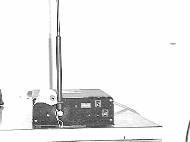
Click to zoom
Application Details
- Equipment Class
- TNB - Licensed Non-Broadcast Station Transmitter
- Date of Grant
- Nov 21, 1999
- Application Purpose
- Original Equipment
- Date of Application
- Aug 25, 1999
- Equipment Note
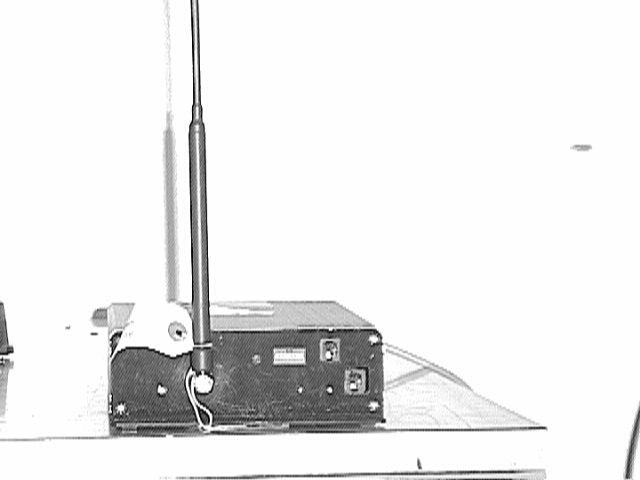
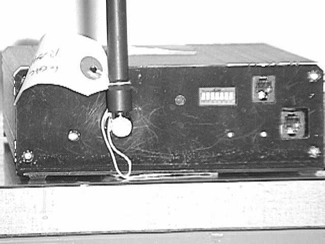
- Radio Base Station
- Frequency Range
- 450.00000000 - 470.00000000
- Country
- United States
Documents & Files
Document Text
Text extracted from the exhibit documents filed with the FCC. Open a document above to read the original.
Users Manual
The Electronic Server Pad (ESP) System Guide1 ADVANTAGE SERIES The Electronic Server Pad (ESP) System Guide Geac Computers, Inc. Part # 90102804345 2 The Electronic Server Pad (ESP) System Guide No part of this document may be reproduced, transmitted, transcribed, stored in retrieval system, or translated into any language or computer language, in any form or by any means, electronic, mechanical, manual, or otherwise without the prior written consent of Geac Computers Incorporated. Geac Computers, Inc. makes no representation or warranties in respect to the contents of this document and specifically disclaims any implied warranties of merchantability or fitness for any particular purposes. Furthermore, Geac reserves the right to revise this document and to make changes from time to time without being obligated to notify any person of such revisions or changes. The Software described in his document is furnished under a Software License Agreement. The Software may be used only in accordance with the terms of the license agreement. It is against the law to copy the Software on tape, disk, or any other medium for purposes other than that described in the license agreement. FEDERAL COMMUNICATIONS COMMISSION (FCC) RADIO FREQUENCY INTERFERENCE STATEMENT WARNING NOTE: This equipment has been tested and found to comply with the limits for a Class A digital device, pursuant to Part 15 of the FCC Rules. These limits are designed to provide reasonable protection against harmful interference when the equipment is operated in a commercial environment. This equipment generates, uses and can radiate radio frequency energy and, if not installed and used in accordance with the instructions, may cause harmful interference to radio communications. Operation of this equipment in a residential area is likely to cause harmful interference in which case the user will be required to correct the interference at his own expense. NOTICE: This documentation may include information about optional ADVANTAGE software packages. Inclusion of this information does not imply that it is part of the standard ADVANTAGE software. These option software packages include, but are not excluded to, Hotel Interface, Labor Analysis, Credit Authorization, Beverage Dispenser Interface, ADVANTAGE Polling Manager, and ADVANTAGE Communications Manager. ©Copyright 1999, Geac Computers, Inc., Restaurant Systems Division . All rights reserved. VISION is a trademark Geac Computers, Incorporated. Epson is a registered trademark of Seiko Epson Corporation. UNIX is a registered trademark of Bell Telephone Laboratories. Intel is a registered trademark of Intel Corporation. SCO is a registered trademark of the Santa Cruz Operation, Inc. The Electronic Server Pad (ESP) System Guide3 Introduction to the Electronic Server Pad (ESP) System Remanco's revolutionary Electronic Server Pad (ESP) is the ultimate in portable, order entry technology for table service restaurants. Each ESP contains a battery powered radio transmitter and receiver that sends information back and forth to the system through a radio base station, which operates off a radio frequency. This compact terminal allows the server to send order s directly from the guest's table to the kitchen or the bar. The ESP is backlit making the keypad easily accessible in dimly lit environments. The ESP's single order entry system eliminates waiting in line for stationary terminals and speeds the delivery of food and drink orders. The result is improved customer service and more table turns. The ESP reduces entry errors, and there is no need to write down the order before entering it on a stationary terminal. Add-on sales such as coffee and desserts are always captured. Each course on the order can be timed by the server, and sent to print when the guest is ready. Managers with the ESP can discretely open checks to be sure drinks have been added, or to see what a customer having before approaching a table to ask "How is your Filet Mignon?". ESP's provide more control for a busy floor manager to effectively manage the restaurant. Servers can provide more attentive service by spending more time with each customer. A larger number of guests can be served, tables are turned faster, and servers operate more efficiently. The ESP allows extra time for upselling that results in more revenues for the restaurant and better tips for the servers. Drinks can be delivered to the table by a runner before the server has even left the table side. Server can be notified at the table if an item is out of stock, or about the number of specials left. Alternatives can be suggested and ordered on the spot. Each server is assigned a Remanco ESP terminal prior to his/her shift. Ordering capabilities can be individually programmed. The ESP's server assignments can easily be changed by a manager at any time. The Remanco ESP is the ultimate tool for hospitality business owners for increasing sales, lowering food, beverage, and labor costs, enhancing server productivity, and providing repeat business from very satisfied customers. Key Features • Orders are entered quickly using alphabetic, numeric, or price lookups (PLU's). • If using alpha entry, servers need only enter the first few letters (or a mnemonic abbreviation) of the item to be ordered (i.e. if ordering coffee, the server might enter "cf..."). The system will search for an item which matches the alpha-entry. • Servers are notified right at the table if an item is out of stock, or if the quantity ordered is available. • The ESP can be configured to print checks at a nearby printer. • Durable, hand-held unit, can be carried easily. • The quiet and unobtrusive ESP does not compromise the ambiance of the restaurant. 4 The Electronic Server Pad (ESP) System Guide ESP Documentation The ESP Guide provides information on the ESP system hardware, software configuration requirements, operational information, and some troubleshooting techniques for the most common ESP system …
Text truncated - open the document above for the full version.
Block Diagram
6303 CPU EPROM Power Supply Analog Transmit Circuit Analog Receive Circuit Johnson Data Telemetry Radio Module RBSIII Block Diagram 6303 CPU EPROM 64180 CPU EPROM RAM RS485 Interface
Schematics
Date: May 6, 1999Sheet 2of 3 SizeDocument NumberREV C9030050XXXXA1 Title NEW RBS Digital board 175 LEDGE STREET NASHUA, NH RESTAURANT SYSTEMS DIVISION GEAC COMPUTERS, INC. REVDESCRIPTIONAPP'D BY (2-3 FOR RBS#1) 1 2 DRN970 10/19/93 3ECN 3564 3/10/98 ECN 3477 6/26/95 R20 100K R47 100K 1 3 2 JUMP1 JUMPER 3 RESET 34 CS0 22 CS1 24 CS2 23 RS0 36 RS1 35 E 25 R/W 21 IRQA 38 IRQB 37 D0 33 D1 32 D2 31 D3 30 D4 29 D5 28 D6 27 D7 26 GND 1 VCC 20 PA0 2 PA1 3 PA2 4 PA3 5 PA4 6 PA5 7 PA6 8 PA7 9 CA1 40 CA2 39 PB0 10 PB1 11 PB2 12 PB3 13 PB4 14 PB5 15 PB6 16 PB7 17 CB1 18 CB2 19 U16 6321 COM1RESET* +5V RESET 34 CS0 22 CS1 24 CS2 23 RS0 36 RS1 35 E 25 R/W 21 IRQA 38 IRQB 37 D0 33 D1 32 D2 31 D3 30 D4 29 D5 28 D6 27 D7 26 GND 1 VCC 20 PA0 2 PA1 3 PA2 4 PA3 5 PA4 6 PA5 7 PA6 8 PA7 9 CA1 40 CA2 39 PB0 10 PB1 11 PB2 12 PB3 13 PB4 14 PB5 15 PB6 16 PB7 17 CB1 18 CB2 19 U13 6321 A0 10 A1 9 A2 8 A3 7 A4 6 A5 5 A6 4 A7 3 A8 25 A9 24 A10 21 A11 23 A12 2 A13 26 A14 27 CE 20 OE 22 VPP 1 O0 11 O1 12 O2 13 O3 15 O4 16 O5 17 O6 18 O7 19 GND 14 VCC 28 U7 27C256 DIP AA0DA0RESET* D0 3 D1 4 D2 7 D3 8 D4 13 D5 14 D6 17 D7 18 OC 1 G 11 Q0 2 Q1 5 Q2 6 Q3 9 Q4 12 Q5 15 Q6 16 Q7 19 U9 74HC373 A0 10 A1 9 A2 8 A3 7 A4 6 A5 5 A6 4 A7 3 A8 25 A9 24 A10 21 A11 23 A12 2 A13 26 A14 1 CS 20 WE 27 OE 22 D0 11 D1 12 D2 13 D3 15 D4 16 D5 17 D6 18 D7 19 VCC 28 GND 14 U4 62256 DA0AA0AA0DA0 AA[0..15] DA[0..7] X1 2 EX2 3 RESET 6 NMI 4 IRQ1 5 P10 13 P11 14 P12 15 P13 16 P14 17 P15 18 P16 19 P17 20 P21 9 P22 10 P23 11 P24 12 P30 37 P31 36 P32 35 P33 34 P34 33 P35 32 P36 31 P37 30 P40 29 P41 28 P42 27 P43 26 P44 25 P45 24 P46 23 P47 22 AS 39 R/W 38 E 40 STBY 7 P20 8 G N D 1 V C C 2 1 U18 6303 R35 100K Y2 3.579545MHz +5V RESET* AUDIOR AUDIOX XMIT SDINL SDOUTL TXEN* RADIO* DATA CLOCK LOCK RCV DA0 +5V RESET* AUDIOR AUDIOX XMIT SDINL SDOUTL TXEN* RADIO* CLOCK DATA LOCK RCV +5VVCC +5V +5V +5V C33 20pF C32 20pF R34 100K R37 100K C27 .1uF R36 100K R21 10 OHMS C34 10uF 12 13 11 U15D 74HC00 1 2 3 U23A 74HC08 DA1 DA2 DA3 DA4 DA5 DA6 DA7 AA8 AA9 AA10 AA11 AA12 AA13 AA14 AA15 RESET* IRQA1* WRA* EA SDINL SDOUTL TXEN* +5V +5V +5V +5V +5V +5V NOT USED FOR RBS C6 .1uF 5 6 U12C 74HC14 4 5 6 U19B 74HC00 R29 100K 9 8 U12D 74HC14 A 14 B 13 G 15 Y0 12 Y1 11 Y2 10 Y3 9 U10B 74HC139 DA1 DA2 DA3 DA4 DA5 DA6 DA7 AA1 AA2 AA3 AA4 AA5 AA6 AA7 AA1 AA2 AA3 AA4 AA5 AA6 AA7 AA8 AA9 AA10 AA11 AA12 AA13 AA14 DA1 DA2 DA3 DA4 DA5 DA6 DA7 EA* EA* RAMA* WRTA* WRTA* AA15 +5V C16 .1uF C8 .1uF AA1 AA2 AA3 AA4 AA5 AA6 AA7 AA8 AA9 AA10 AA11 AA12 DA1 DA2 DA3 DA4 DA5 DA6 DA7 AA0 AA1 DA0 DA1 DA2 DA3 DA4 DA5 DA6 DA7 PIAA1* EA IRQA1* WRA* ROMA* EA* ROMA* +5V +5V +5V +5V +5V C25 .1uF COM2 COM3 COM4 COM5 COM6 COM7 COM8 COM9 COM10 COM11 COM12 COM13 COM14 COM15 COM16 COM17 COM18 COM19 COM20 AA0 AA1 DA0 DA1 DA2 DA3 DA4 DA5 DA6 DA7 PIAA2* EA IRQA1* WRA* +5V +5V R30 100K 12 13 11 U19D 74HC00 COM11 COM12 COM13 COM14 COM15 COM16 +5V (4000) (5000) (6000-7FFF) RESET 34 CS0 22 CS1 24 CS2 23 RS0 36 RS1 35 E 25 R/W 21 IRQA 38 IRQB 37 D0 33 D1 32 D2 31 D3 30 D4 29 D5 28 D6 27 D7 26 GND 1 VCC 20 PA0 2 PA1 3 PA2 4 PA3 5 PA4 6 PA5 7 PA6 8 PA7 9 CA1 40 CA2 39 PB0 10 PB1 11 PB2 12 PB3 13 PB4 14 PB5 15 PB6 16 PB7 17 CB1 18 CB2 19 U11 6321 A0 10 A1 9 A2 8 A3 7 A4 6 A5 5 A6 4 A7 3 A8 25 A9 24 A10 21 A11 23 A12 2 A13 26 A14 27 CE 20 OE 22 VPP 1 O0 11 O1 12 O2 13 O3 15 O4 16 O5 17 O6 18 O7 19 GND 14 VCC 28 U5 27C256 DIP 12 13 11 U23D 74HC08 AB0 AB1 AB2 AB3 AB4 AB5 DB0 DB1 DB2 DB3 DB4 DB5 AB0 AB1 PIAB1* RESET* RAMA* PIAA1* PIAA2* +5V OLD "LAN BOARD" OLD "DIGITAL BOARD" 9 10 8 U19C 74HC00 A0 10 A1 9 A2 8 A3 7 A4 6 A5 5 A6 4 A7 3 A8 25 A9 24 A10 21 A11 23 A12 2 A13 26 A14 1 CS 20 WE 27 OE 22 D0 11 D1 12 D2 13 D3 15 D4 16 D5 17 D6 18 D7 19 VCC 28 GND 14 U8 62256 D0 3 D1 4 D2 7 D3 8 D4 13 D5 14 D6 17 D7 18 OC 1 G 11 Q0 2 Q1 5 Q2 6 Q3 9 Q4 12 Q5 15 Q6 16 Q7 19 U3 74HC373 DB0 DB1 DB2 DB3 DB4 DB5 AB0 AB1 AB2 AB3 AB4 AB5 AB0 AB1 AB2 AB3 AB4 AB5 DB0 DB1 DB2 DB3 DB4 DB5 AB[0..15] DB[0..7] AA12 AA13 AA14 X1 2 EX2 3 RESET 6 NMI 4 IRQ1 5 P10 13 P11 14 P12 15 P13 16 P14 17 P15 18 P16 19 P17 20 P21 9 P22 10 P23 11 P24 12 P30 37 P31 36 P32 35 P33 34 P34 33 P35 32 P36 31 P37 30 P40 29 P41 28 P42 27 P43 26 P44 25 P45 24 P46 23 P47 22 AS 39 R/W 38 E 40 STBY 7 P20 8 G N D 1 V C C 2 1 U6 6303 C11 20pF C10 20pF Y1 3.579545MHz R49 100K CS 1 CLK 2 DI 3 DO 4 VCC 8 NC 7 DRG 6 VSS 5 U24 93C06 R3100K R58 1K DB0 DB1 DB2 DB3 DB4 DB5 RESET* IRQB1* WRA* DATA CLOCK NVRAM +5V +5V +5V C13 .1uF R2 10 OHMS R5 100K C12 10uF 9 10 8 U15C 74HC00 R4 10K 1 2 3 U15A 74HC00 R50 100K 9 10 8 U23C 74HC08 R1 10K R6 100K DB6 DB7 AB8 AB9 AB10 AB11 AB12 AB13 AB14 AB15 AUDIOX PGMCHG* WRB* WRB* EB XMIT AUDIOR NVRAM RADIO* CLOCK DATA RCV RCV LOCK RESET* +5V +5V +5V +5V NOT USED FOR RBS C7 .1uF 1110 U12E 74HC14 A 2 B 3 G 1 Y0 4 Y1 5 Y2 6 Y3 7 U10A 74HC139 1312 U12F 74HC14 4 5 6 U15B 74HC00 R7 100K DB6 DB7 AB6 AB7 AB6 AB7 AB8 AB9 AB10 AB11 AB12 AB13 AB14 DB6 DB7 EB* EB* RAMB* WRTB* WRTB* AB13 AB14 AB15 PIAB1* RAMB* AB15ROMB* (4000) (6000) C14 .1uF C9 .1uF AB6 AB7 AB8 AB9 AB10 AB11 AB12 DB6 DB7 DB0 DB1 DB2 DB3 DB4 DB5 DB6 DB7 EB IRQB1* WRB* ROMB* EB* +5V +5V +5V +5V+5V THIS DOCUMENT MAY NOT BE REPRODUCED BY ANY MEANS WITHOUT THE EXPRESSED PERMISSION OF GEAC COMPUTERS, RESTAURANT SYSTEMS DIVISION COPYRIGHT(C) 1992-99 GEAC COMPUTERS, INC. S3 SW SPDT R40 100K 1 2 3 U19A 74HC00 PGMCHG* COM1 COM2 COM3 COM4 COM5 COM6 COM7 COM8 COM9 COM10 COM17 COM18 COM19 COM20 +5V
Schematics
Date: October 4, 1993Sheet 1of 1 SizeDocument NumberREV C1 Title NEW RBS LAN board REMANCO International, Inc. REVDESCRIPTIONAPP'D BY ** D0 2 D1 3 D2 4 D3 5 D4 6 D5 7 D6 8 D7 9 CS0 14 CS1 15 CS2 16 DISTR 25 DISTR 24 DOSTR 21 DOSTR 20 A0 31 A1 30 A2 29 INTR 33 DDIS 26 MR 39 RTS 36 CTS 40 DTR 37 DSR 41 DCD 42 RI 43 OUT1 38 OUT2 35 SIN 11 SOUT 13 RCLK 10 BOUT 17 X2 19 X1 18 NU 1 NU 12 NU 23 NU 32 NU 34 CSOUT 27 V C C 4 4 G N D 2 2 A 2 8 U8 16C450 PLCC + SOCKET +5V 4 1 7 6 2 3 8 5 U11 75176 D0 D1 D2 D3 D4 D5 A0 A1 A2 A3 A4 A5 D0 D1 D2 D3 D4 D5 D0 D1 D2 D3 D4 D5 A0 12 A1 11 A2 10 A3 9 A4 8 A5 7 A6 6 A7 5 A8 27 A9 26 A10 23 A11 25 A12 4 A13 28 A14 29 A16 2 D0 13 D1 14 D2 15 D3 17 D4 18 D5 19 D6 20 D7 21 CS 22 OE 24 A15 3 NU 30 VPP 1 PGM 31 G N D 1 6 V C C 3 2 U2 271024 + SOCKET 78 56 34 68 SIP 78 56 34 68 SIP 56 34 68 SIP 12 RP1A 12 RP3A 78 12 RP2A C8 .1uF A0 A1 A2 A3 A4 A5 A[0..18] D[0..7] A0 A1 A2 A3 A4 A5 A6 A7 A8 A9 A10 A11 +5V A0 12 A1 11 A2 10 A3 9 A4 8 A5 7 A6 6 A7 5 A8 27 A9 26 A10 23 A11 25 A12 4 A13 28 A14 3 A16 2 D0 13 D1 14 D2 15 D3 17 D4 18 D5 19 D6 20 D7 21 V + 3 2 CS 22 WR 29 OE 24 A15 31 N.C. 30 N.C. 1 G N D 1 6 U5 621024 PLACE ALL COMPONENTS WITH * CLOSE TOGETHER * ** * 1 4 1 5 1 6 1 7 1 2 RP6A 10K SIP 56 68 SIP 34 RP7B Y1 12.288MHZ 1 3 C3 20pF C4 20pF RESET* E RD* WR* +5V +5V XTAL 2 EXTAL 3 RESET 7 E 60 WAIT 4 RD 63 WR 62 LIR 61 STATUS 12 ME 59 IOE 58 REF 57 BUSREQ 6 BUSACK 5 HALT 56 NMI 8 INT0 9 INT1 10 INT2 11 TXA1 48 RXA1 49 TXA0 45 RXA0 46 DCD0 44 CTS0 43 RTS0 42 CKS 53 RXS/CTS1 52 TXS 51 DREQ0/CKA0 47 TEND0/CKA1 50 DREQ1 54 TEND1 55 A0 13 A1 14 A2 15 A3 16 A4 17 A5 18 A6 19 A7 20 A8 21 A9 22 A10 23 A11 24 A12 25 A13 26 A14 27 A15 28 A16 29 A17 30 A18/TOUT 31 D0 34 D1 35 D2 36 D3 37 D4 38 D5 39 D6 40 D7 41 CLK 64 GND 1 GND 33 VCC 32 U1 64180 + SOCKET 1 1 0 RP6I 10K SIP 1 1 0 RP5I 10K SIP 1 1 0 RP8I 10K SIP 1 8 1 9 ME* IOE* RLANINT* TXD1 RXD1 TXD0 RXD0 +5V +5V +5V 9 8 U3D 74HC14 1110 U3E 74HC14 1312 U3F 74HC14 56 R1 10 OHMS C2 .1uF 12 RP7A 68 SIP 34 68 SIP 78 12 RP4A D1 3 D2 4 D3 7 D4 8 D5 13 D6 14 D7 17 D8 18 CLK 11 CLR 1 Q1 2 Q2 5 Q3 6 Q4 9 Q5 12 Q6 15 Q7 16 Q8 19 U7 74HC273 C1 10uF A6 A7 A8 A9 A10 A11 A12 A13 A14 A12 A13 A14 A15 A16 A17 D0 D1 D2 D3 D4 D5 D6 D7 CSOUT* RESET* +5V +5V A15 A16 D0 D1 D2 D3 D4 D5 D6 D7 1 3 1 4 1 5 1 6 1 7 1 8 1 9 1 2 RP5A 10K SIP PLACE ALL COMPONENTS WITH ** CLOSE TOGETHER C21 LED R3 0 OHM R2 0 OHM C6 .1uF R19 330 D6 D7 A6 A7 A8 A9 A10 A11 A12 A13 A14 D6 D7 A16 WR* RD* D6 D7 A0 A1 A2 CSROM* A7 A6 A5* DOSTR* DISTR* RESET RLANINT CSRAM* TX1EN WATCHDOG* A15 +5V +5V +5V +5V +5V ** ** ** ** ** ** ** C11 .1uF R10 2K R9 510K R8 510K C14 30pF C13 .1uF C12 30pF R7 10 OHMS C15 10uF SOUT SIN +5V +5V VCC RESET_IN* Y2 1.7898MHZ 1 2 3 4 5 6 JP2 HEADER 6 +5V 78 RP7D 68 SIP 1 2 3 TP1 HEADER 3 I0 1 I1 2 I2 3 I3 4 I4 5 I5 6 I6 7 I7 8 I8 9 I9 11 F0 19 F1 18 F2 17 F3 16 F4 15 F5 14 F6 13 F7 12 G N D 1 0 V C C 2 0 U6 18CV8-25 C9 .1uF CSSW* CSOUT* CSROM* CSRAM* RLANINT* A5* DISTR* DOSTR* XMIT* RECV* +5V 3 4 U3B 74HC14 1 2 3 4 5 6 7 14 13 12 11 10 9 8 S1 SW DIP-7 1 3 1 4 1 5 1 6 1 7 1 8 1 9 1 2 RP8A 10K SIP CSSW* E A17 A7 A6 A5 IOE* ME* RD* WR* RLANINT TXD0 +5V R15 100 A1 2 A2 4 A3 6 A4 8 G 1 Y1 18 Y2 16 Y3 14 Y4 12 U9A 74HCT240 A1 11 A2 13 A3 15 A4 17 G 19 Y1 9 Y2 7 Y3 5 Y4 3 U9B 74HCT240 D0 D1 D2 D3 D4 D5 D6 D7 RESET Q1 2N3906 1 2 U3A 74HC14 VISION INTERFACE RESET CIRCUIT VOUT 1 VCC 2 GND 3 PFI 4 VBATT 8 RESET 7 WDI 6 PFO 5 U4 MAX690 4 1 7 6 2 3 8 5 U10 96176 C7 .1uF C18 .1uF RESET* WATCHDOG* VCC +5V R6 0 OHM RESET_IN* R5 10K R18 10K R16 10K L2 27uH C19 .001uF L127uH TX1EN TXD1 RXD1 1 2 3 4 J1 TELCO-4 R17 100 TZ2 TRANZORB TZ1 TRANZORB C20 .001uF C5 .1uF C10 .1uF C16 .1uF C17 10uF RXD0 THIS DOCUMENT MAY NOT BE REPRODUCED BY ANY MEANS WITHOUT THE EXPRESSED PERMISSION OF REMANCO INTERNATIONAL, INC. COPYRIGHT 1993 REMANCO INTERNATIONAL, INC. R4 4.7K D2 1N914 D1 1N914 +5V 5 6 U3C 74HC14
Test Report
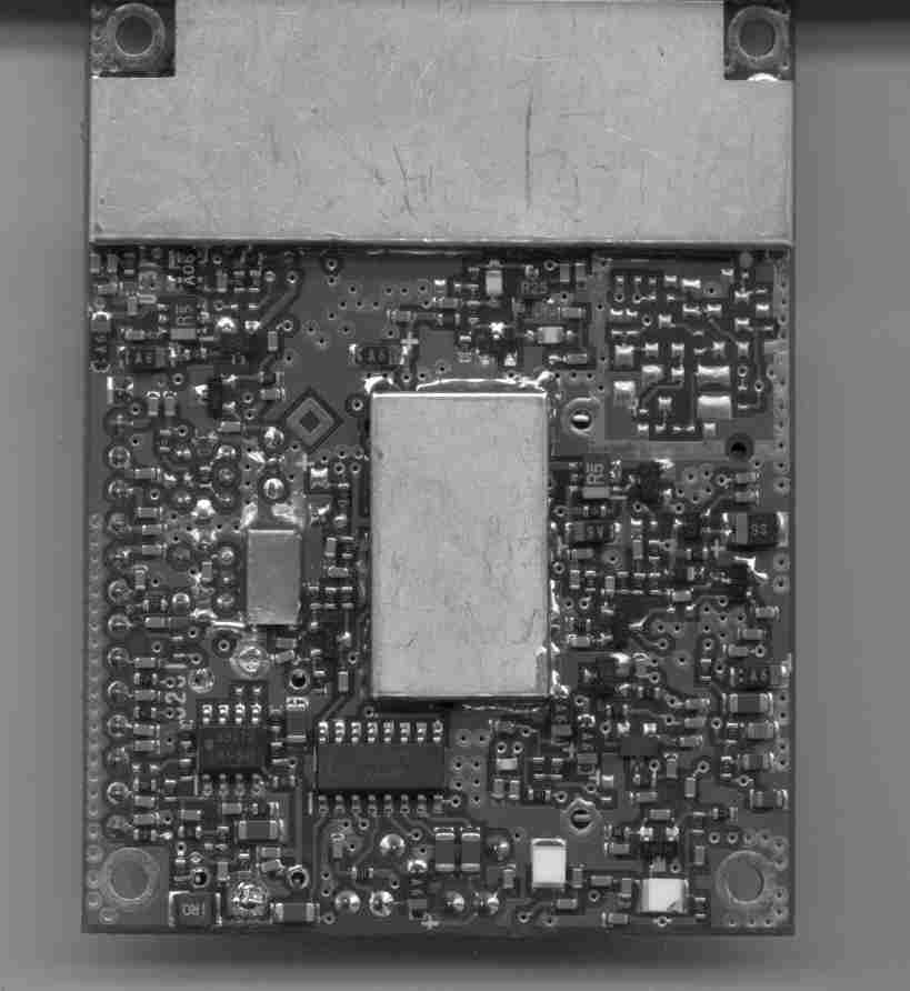
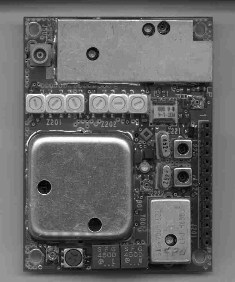
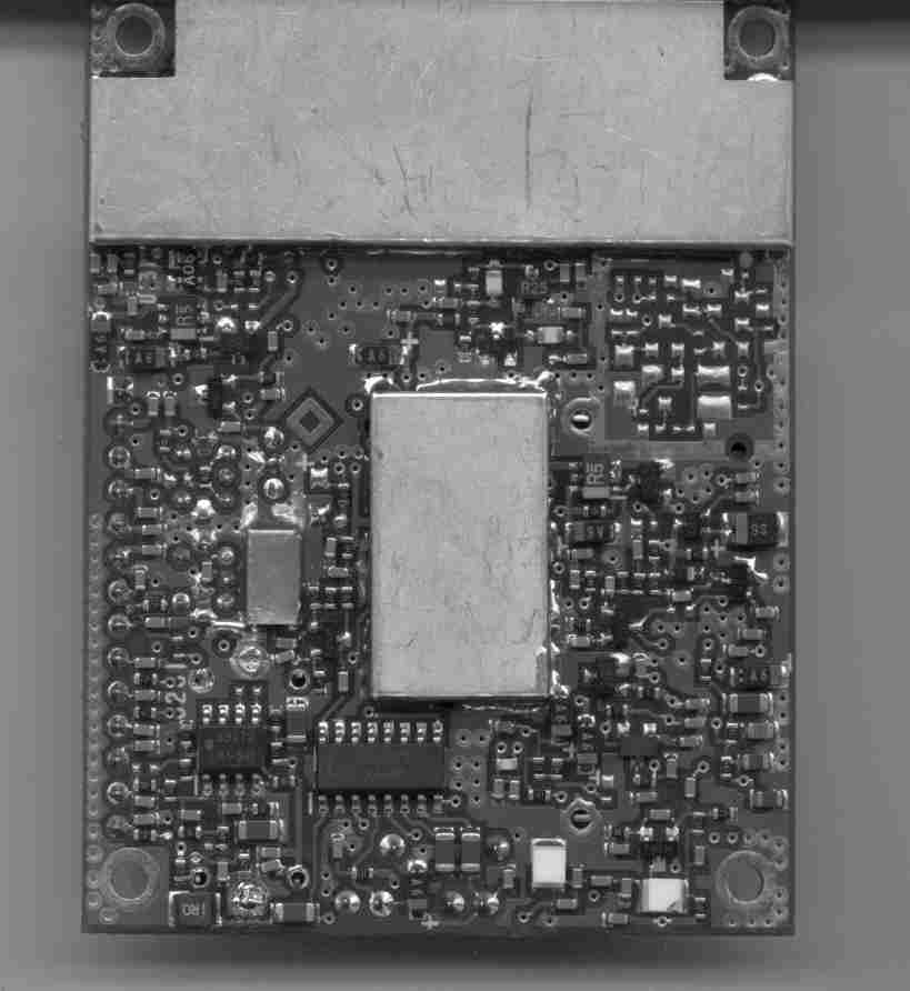
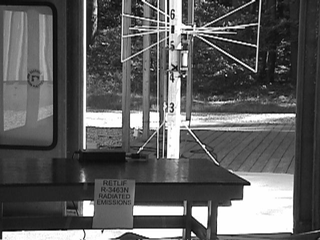
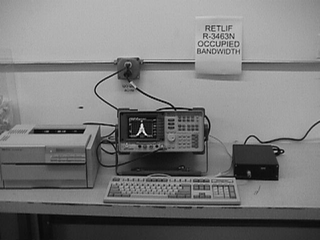
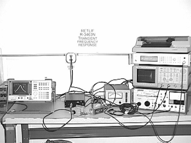
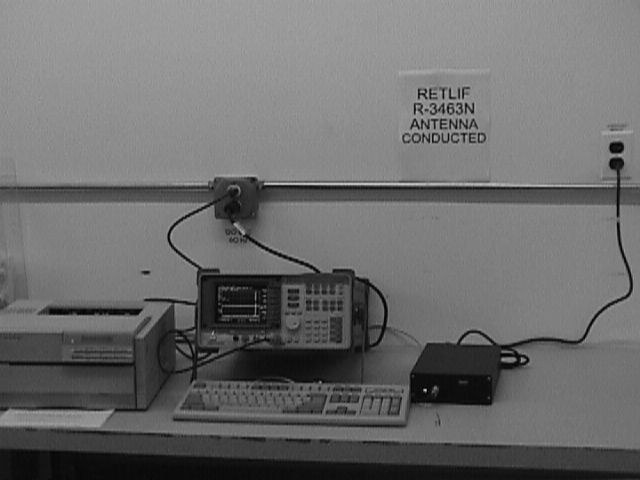
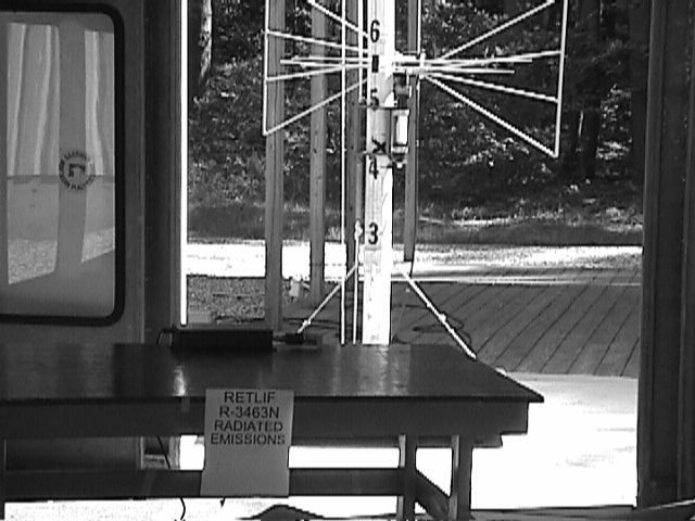
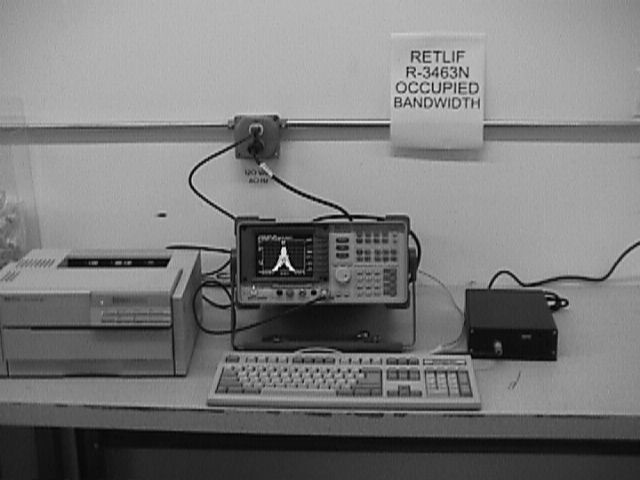
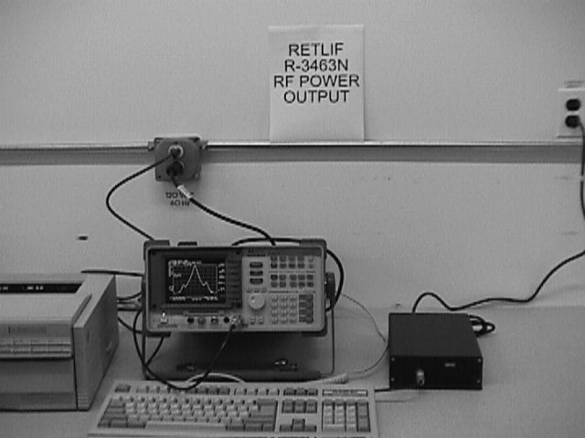
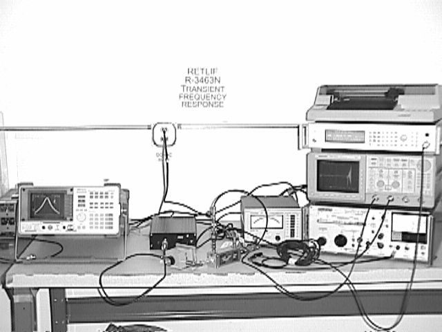
April 7, 1998 Federal Communications Commission Equipment Approval Services PO Box 358315 Pittsburgh, PA 15251-5315 Dear Sir/Madam: Enclosed you will find an application for Certification of a Radio Base Station (RBSIII), Model No. 3001, FCC ID: OOURBSIII. Certification is requested under Part 2 and Part 90 of the Commission’s rules. This application is being filed by Retlif Testing Laboratories on behalf of Remanco International, Inc., a subsidiary of Geac Computers, Inc. You should soon receive a hard copy of the 159 form and applicable filing fee. I trust that you will find the enclosed application to be complete; however, should you have any questions or require any additional information, please feel free to contact us. Very truly yours, RETLIF TESTING LABORATORIES Scott Wentworth Branch Manager Enc. (as stated) Retlif Test Report: R-3463N FCC ID: OOURBSIII Certification Application in accordance with 47CFR Ch. 1 (10-1-98) Part 2, Subpart J Equipment Authorization Procedures, Part 90, Subpart C, Industrial/Business Radio Pool, including additional referenced subparts and subsections covering Radio Base Station (RBSIII) in which is a RF Digitally Synthesized Radio Module Transceiver Operating in 450-470MHz Range, part of the Electronic Server Pad System, A table service restaurant order entry and information retrieval system TECHNICAL REPORT 47CFR Part 2.1022(c) Applicant/Manufacturer:Remanco International, Inc. A subsidiary of Geac Computers, Inc. 175 Ledge Street Nashua, NH 03060 Test Sample:Radio Base Station (RBSIII) FCC ID No.:XXXRBSIII Model No.:3001 Power Requirements:120VAC, 1 Ø, 60Hz The RBSIII is the base station part of the Electronic Server Pad System and contains the RF module which operates, and can be programmed for, a frequency in the 450-470MHz range. The RBSIII has an external connected 18" antenna, which is position adjustable. The RBSIII is located in a central location in the restaurant to optimize the system operation. Retlif Test Report: R-3463N FCC ID: OOURBSIII TECHNICAL REPORT 47CFR Part 2.1022(c) Type of Emission:16K0F1D Frequency Range:450 - 470MHz Test Frequency:467.875MHz Maximum Measured Power Output:1.62 watts The following information is supplied as electronic attachments: - Installation and Operating Instructions - Tune-up Procedure - Block Diagram - Schematics - Circuit Description - FCC ID Label - Internal and External Photographs The following test methods were performed on the test sample in accordance with FCC Rules and Regulations Part 2 and Part 90. This report includes a description of each test method. Actual test data as well as test setup photographs are supplied as electronic attachments. - §2.1046 RF Output (§90.205) - §2.1049 Occupied Bandwidth (§90.209) - §2.1051 Spurious Emissions at Antenna Terminals (§90.210 - §2.1053 Field Strength of Spurious Emissions (§90.205) - §2.1055 Frequency Stability (§90.213) - Transient Frequency Behavior (§90.214) The following test methods were not applicable to this EUT - §2.1047 Modulation Characteristics (§90.211) Retlif Test Report: R-3463N FCC ID: OOURBSIII TEST EQUIPMENT LIST RF Output Power ENTypeManufacturerFrequency RangeModel No.Cal DateDue Date 3128B 20dB AttenuatorLucas WeinscherDC-18GHz212/18/9812/18/99 4895Spectrum AnalyzerHewlett Packard9kHz - 22GHz8593EM 9/18/989/18/99 _________________________________________________________________________________________________________ Occupied Bandwidth ENTypeManufacturerFrequency RangeModel No.Cal DateDue Date 3128B 20dB AttenuatorLucas WeinscherDC-18GHz212/18/9812/18/99 4895Spectrum AnalyzerHewlett Packard9kHz - 22GHz8593EM 9/18/989/18/99 _________________________________________________________________________________________________________ Spurious Emissions at Antenna Terminals ENTypeManufacturerFrequency RangeModel No.Cal DateDue Date 3128B 20dB AttenuatorLucas Weinscher DC-18GHz212/18/9812/18/99 4895Spectrum AnalyzerHewlett Packard 9kHz - 22GHz8593EM 9/18/989/18/99 _________________________________________________________________________________________________________ Field Strength of Spurious Emissions ENTypeManufacturerFrequency RangeModel No.Cal DateDue Date 3116Pre-AmplifierMiteq0.1GHz - 18GHzAFS42-3512/3/9812/3/99 3118Broadband Pre-Amp Electro-Metrics10kHz - 1GHzBPA-10006/24/986/24/99 3258Double Ridge Guide EMCO1-18GHz31154/7/994/7/00 4029Open Area Test Site Retlif3 / 10 MetersRNH6/15/98615/99 4202BiconilogEMCO26MHz - 2GHz31426/10/986/10/99 4895Spectrum AnalyzerHewlett Packard9kHz - 22GHz8593EM 9/18/989/18/99 _________________________________________________________________________________________________________ Frequency Stability ENTypeManufacturerFrequency RangeModel No.Cal DateDue Date 159Frequency CounterLeader10Hz - 1GHzLDC-8259/18/989/18/99 507AC Power SupplyStaco0-140VACE1010VA9/18/989/18/99 520FDigital MultimeterWavetekN/ADM25XT7/6/997/6/00 _________________________________________________________________________________________________________ Transient Frequency Behavior ENTypeManufacturerFrequency RangeModel No.Cal DateDue Date 073Interference Analyzer Electro-Metrics10kHz-1GHzEMC-25 3/9/993/9/00 3117Power SupplyB&K Precision0-30VDC, 3.0A16302/17/992/17/00 3128B 20dB AttenuatorLucas WeinscherDC-18GHz212/18/9812/18/99 313910dB Atten. (50ohm) NardaDC-5GHz768-104/9/994/9/00 3233Graphics PlotterHewlett PackardN/A7470A4/9/994/9/00 34480-11dB Stepatten.Midwest Microwave DC-18GHz10922/17/992/17/00 375Power DividerWeinschel Eng.DC-18GHZ1506A1/28/991/28/00 4001OscilloscopeTektronixN/ATDS 520A3/5/993/5/00 4004RF MillivoltmeterBoonton Electronics 10kHz - 1.2GHz92B10/15/9810/15/99 4895Spectrum AnalyzerHewlett Packard9kHz - 22GHz8593EM 9/18/989/18/99 4910Tee AdapterBruel and Kjaer10kHz-1GHz91-14A10/15/9810/15/99 530AAM/FM Signal Gen. Marconi Instruments 10kHz - 1.2GHz20233/8/993/8/00 532High Pwr. Dir. Coup. Werlatone Inc..01-1000MHzC263012/15/9812/15/99
Test Report
Process Specification DWG. NO. 90101504XXX Sheet 1 of 1 sheets Test Specification RBSIII Equipment required: Oscilloscope, ESPIII, RF Tester (Motorola Service Monitor or Equivalent Device) PROCEDURE: 1. Attach coaxial cable between radio's antenna jack and service monitor 'RF I/O'. 2. Set service monitor to frequency of radio under test and attenuation to 40dB.. 3. Connect a network cable from the RJ-5 connector on the RLAN board to a Remanco Network.. 4. Turn on the power to the RBS and program the radio using the “TOESP” program. 5. Depress the ‘TEST’ button (farthest from the antenna) 5 times to get to the TRANSMIT 1,0,1,0 Mode. 6. Check to achieve a frequency error of less than ±500 Hz. 7. Depress ‘TEST’ button one more time (test 6) to enter Receive Mode. 8. Set service monitor frequency to 52.95 MHz above radio frequency under test and attenuation to 0dB. 9. Move coaxial cable to 'Ant. In' connector and change monitor setting to 'Ant In'. 10. Verify a frequency error of less than ±500 Hz. 11. Disconnect the coaxial cable from the RBSIII. 12. Start ESPIII of the same frequency transmitting 1,0,1,0's. (#2 Key in TEST mode) 13. Adjust R11 to mid range (7 turns from either end. 14. Place RBS in ECHO Mode (test #1). 15. Depress the ‘SEND’ key or cycle power to ESP and verify a “1” appears on the display. 16. Depress '*' key to enter “ALPHA” Mode. 17. Verify Alphabetic keys echo to the display from a distance of at least 15 Feet. 18. Reset RBS. 19. Power Unit up and verify that it has been recognized by the system. 20. Verify that you can access the Vision system (open checks, order items, etc.). Test Mode (Right Push Button) Mode Pushes Function Comments 0 0 Normal Will operate normally 1 1 ECHO Mode Will echo characters sent from ESPIII 2 2 Performance Mode Determines RF performance with ESPIII 3 3 Transmit Low Transmits a continuous "0" 4 4 Transmit High Transmits a continuous "1" 5 5 Transmit High, Low... Transmits continuously "1,0,1,0..." 6 6 Receive Continuously in the Receive mode 4 DWN W. LaSante DATE 5/07/99 Geac Restaurant Systems. 3 CHKDDATE TITLE 2 APP'DDATE TEST PROCEDURE* RBSIII 1DRN REV.CHANGE No.DATEAPP'D Company Confidential DWG. NO. 90101504XXX REV . 1
Test Report
Process Specification DWG. NO. 90101504XXX Sheet 1 of 1 sheets Test Specification RBSIII Equipment required: Oscilloscope, ESPIII, RF Tester (Motorola Service Monitor or Equivalent Device) PROCEDURE: 1. Attach coaxial cable between radio's antenna jack and service monitor 'RF I/O'. 2. Set service monitor to frequency of radio under test and attenuation to 40dB.. 3. Connect a network cable from the RJ-5 connector on the RLAN board to a Remanco Network.. 4. Turn on the power to the RBS and program the radio using the “TOESP” program. 5. Depress the ‘TEST’ button (farthest from the antenna) 5 times to get to the TRANSMIT 1,0,1,0 Mode. 6. Check to achieve a frequency error of less than ±500 Hz. 7. Depress ‘TEST’ button one more time (test 6) to enter Receive Mode. 8. Set service monitor frequency to 52.95 MHz above radio frequency under test and attenuation to 0dB. 9. Move coaxial cable to 'Ant. In' connector and change monitor setting to 'Ant In'. 10. Verify a frequency error of less than ±500 Hz. 11. Disconnect the coaxial cable from the RBSIII. 12. Start ESPIII of the same frequency transmitting 1,0,1,0's. (#2 Key in TEST mode) 13. Adjust R11 to mid range (7 turns from either end. 14. Place RBS in ECHO Mode (test #1). 15. Depress the ‘SEND’ key or cycle power to ESP and verify a “1” appears on the display. 16. Depress '*' key to enter “ALPHA” Mode. 17. Verify Alphabetic keys echo to the display from a distance of at least 15 Feet. 18. Reset RBS. 19. Power Unit up and verify that it has been recognized by the system. 20. Verify that you can access the Vision system (open checks, order items, etc.). Test Mode (Right Push Button) Mode Pushes Function Comments 0 0 Normal Will operate normally 1 1 ECHO Mode Will echo characters sent from ESPIII 2 2 Performance Mode Determines RF performance with ESPIII 3 3 Transmit Low Transmits a continuous "0" 4 4 Transmit High Transmits a continuous "1" 5 5 Transmit High, Low... Transmits continuously "1,0,1,0..." 6 6 Receive Continuously in the Receive mode 4 DWN W. LaSante DATE 5/07/99 Geac Restaurant Systems. 3 CHKDDATE TITLE 2 APP'DDATE TEST PROCEDURE* RBSIII 1DRN REV.CHANGE No.DATEAPP'D Company Confidential DWG. NO. 90101504XXX REV . 1
Contact Information
Applicant
Wayne LaSante(Product Manager)
603-889-5152
Technical Contact
Retlif Testing LaboratoriesJohn Monahan
[email protected]603-497-4600
101 New Boston Road · Goffstown, New Hampshire · United States
Non-Technical Contact
Retlif Testing LaboratoriesScott Wentworth
[email protected]603-497-4600
Technical Specifications
| # | Rule Parts | Frequency Range | Power Output | Emission | Tolerance |
|---|---|---|---|---|---|
| 1 | 90 | 450 MHz - 470 MHz | 770.00 mW | 11K2F1D | 0.0001500000 % |
Other Applications from Remanco International, Inc., a subsidiary of Geac Computers, Inc.
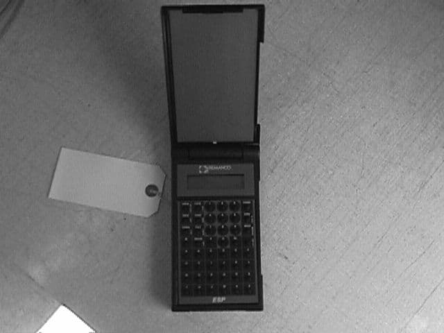
OOUESPIII
Nov 21, 1999Electronic Server Pad
Equipment Class
TNT - Licensed Non-Broadcast Transmitter Worn on Body