OP930ATX1Car Alarm
Detector Electronics Company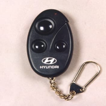
Click to zoom
Application Details
- Equipment Class
- DSC - Part 15 Security/Remote Control Transmitter
- Date of Grant
- Oct 21, 1999
- Application Purpose
- Original Equipment
- Date of Application
- Sep 26, 1999
- Equipment Note
- Car Alarm
- Frequency Range
- 311.00000000 - 311.00000000
- Company
- Detector Electronics Company
- Country
- South Korea
Documents & Files
Document Text
Text extracted from the exhibit documents filed with the FCC. Open a document above to read the original.
Users Manual
OPERATING MANUAL This device complies with part 15 of the FCC rules. Operation is subject to the following two conditions : (1)This device may not cause harmful interference, and (2)This device must accept any interference received, including interference that may cause undesired operation. Caution : Any changes or modifications in construction of this device which are not expressly approved by the party responsible for compliance could void the user’s authority to operate the equipment. 1. Name of products : Wireless Vehicle Alarm System 2. Model No. : D – 300A (Transmitter ; D-300AT, Receiver ; D-300AR) 3. Operation (1) Press button 1 of the transmitter for 1 sec, lock the door with the 1 chirp sound and 1 parking lights flash, and arm & cut off the starter after 5 sec. (2) Press button 2 of the transmitter for 1 sec, unlock the door with the 2 chirp sounds and 2 parking lights flashes, and disarm & release the starter at once. (3) Press button1 of the transmitter for 3 sec, blow the siren with the parking lights flash for 3 min. To stop the siren, press button 2 for 1 sec. (4) Press button 2 of the transmitter for over 3 sec, release the trunk. At that time, unlock the door and disarm also. (5) Whenever press button 3 of the transmitter for 3 sec, change the mode as follows. a. Silent Mode : Change the mode after 8 chirps. All function is operated but chirp sounds. b. Valet Mode : Change the mode after 6 chirps. Door lock & unlock and trunk release are only operated without the chirp sound. Interrupt the arming & the start kill. c. Normal Mode : Change the mode after 4 chirps. All function is operated normally. (6) To disarm without the transmitter if it was lost, damaged or disable, turn the vehicle’s ignition key to the “on” position and the “off” position repeatedly by twice within 15 sec after get on the car and close the door. 4. Specification (1) Transmitter : a. voltage : 12V battery b. frequency : 311.0 MHz (2) Receiver : a. voltage : 12V battery b. frequency : 311.0 MHz (3) Operating Temperature : - 10°C ∼ 60°C
External Photos
EXTERNAL TOP SIDE EXTERNAL BOTTOM SIDE FCC ID : OP930ATX1
ID Label/Location Info
PROPOSED FCC ID. LABEL AND MARKING BOTTOM SIDE
ID Label/Location Info
PROPOSED FCC ID. LABEL AND MARKING BOTTOM SIDE
Internal Photos
INTERNAL TOP SIDE INTERNAL BOTTOM SIDE FCC ID : OP930ATX1 FCC ID : OP930ATX1
Operational Description
CIRCUIT EXPLANATION 1. Organization and summary (1) Included : a. Transmitter b. Receiver (2) Summary This products is the vehicle alarm system, used with the frequency of 311.0 MHz, that is arm/disarm, door lock/unlock, door open/shock detect and panic siren function. 2. Circuit (1) Transmitter Press the buttons of the transmitter, input the voltage to IC1 and output the ID code from the encode IC. It oscillates X1(SAW generator) through R5 and the oscillation frequency F0(311.0 MHz) is amplified through TR(Q1). It is emitted through the pattern antenna. The encode IC’s code output through R5 consists of ON(1) and OFF(0) in serial. Its ON signal makes X1 oscillated as the frequency of 311.0 MHz and OFF signal makes X1 not oscillated. The oscillated signal goes to Q1(TR) and Q1 makes LED, L1 & coil(pattern antenna) operated. Then, the pattern antenna has the high frequency signal and it‘s emitted in the air. (2) Receiver The RF signal emitted from the transmitter is received through the RF module, which is produced by the surface mount technology and get the high reliability. It is composed of the SRG (Super Regenerative Demodulation), which consists of the circuits, RF oscillation(colpits) & LPF(low pass filter). The received signal goes through the SRG to be the low frequency signal. It is amplified by the OP Amp. to be the square wave. It is input to U1(CPU) to control all input or output. The received signal is amplified by RF Amp. and oscillated through MQ2(TR) to be the signal eliminated the carrier. The RF oscillation(colpits) is coupled with the carrier by L(ML2) & C(MC6). The signal eliminated the carrier through LPF(MR9, MC12) is amplified by OP Amp(MIC1) to be the square wave so that CPU can be recognized. Thus, CPU controls all function of the vehicle alarm system.
Test Report
KTL Korea Testing Laboratory Page 1 of 15 TEST REPORT This test report only responds to the tested sample and shall not be reproduced except in full without written approval of the the Korea Testing Laboratory. Tested and reported by Reviewed by Soun-Kweon Seol , Senior Engineer Seok-Jin Kim , EMC Team Leader KOREA TESTING LABORATORY FG101-01-02-00 222-13, Guro-Dong Guro-Gu Seoul Korea 152-053 http://www.ktl.re.kr Ref. Report No. 99-341-047 Name and address of the applicant Detector Electronics Company 277-2 Yangpyong-Dong 4 Ka, Youngdeungpo-Ku, Seoul, Korea 150-104 Standard / Test regulation FCC Part 15, Subpart C Test result Pass Incoming date : August 27, 1999 Test item(s) ; Security/Remote Control Transmitter (Car Alarm) Model/type ref. ; D-300AT Manufacturer ; Detector Electronics Company Additional information ; -Required Authorization :Certification -FCC ID. : OP930ATX1 Test date : September 10~16, 1999 Issue date : September 22, 1999 Ref. Report No. 99 - 341 - 047 Page 2 of 15 TABLE OF CONTENTS . GENERAL INFORMATION ................................................................................................................... 3 1. Grantee Name and Mailing Address 2. Manufacturer's Name and Mailing Address 3. Equipment Descriptions 4. Rules and Regulations 5. Measuring Procedure 6. Place of Measurement 7. Date of Measurement . GENERAL REQUIREMENTS OF THE EUT ...................................................................................... 5 1. Labelling Requirement (Section 15.19) 2. Information to User (Sections 15.21) 3. Special Accessories (Section 15.27) 4. Compliant Conditions (Section 15.231) 5. Modification of the Equipment Under Test . INPUT POWER MEASUREMENT (Section 15.31)............................................................................. 6 . RADIATED EMISSION MEASUREMENT (Section 15.231)............................................................ 7-13 1. Test Procedure 2. Photograph for the worst case configuration 3. Sample Calculation 4. Measurement Data 5. Reference Data . OCCUPIED BANDWIDTH MEASUREMENT (Section.15.231)...................................................... 14 . TEST EQUIPMENTS USED FOR FCC COMPLIANCE TESTING................................................ 15 Ref. Report No. 99 - 341 – 047 Page 3 of 15 . GENERAL INFORMATION 1. Grantee Name and : Detector Electronics Company Mailing Address 277-2 Yangpyong-Dong, Youngdeungpo-Ku, Seoul, Korea 150-104 2. Manufacturer's Name and : Detector Electronics Company Mailing Address 277-2 Yangpyong-Dong, Youngdeungpo-Ku, Seoul, Korea 150-104 3. Equipment Descriptions 3.1 Operating Frequency : 311.0MHz 3.2 Type of Emission : Pulse Code Signal 3.3 Power Supply : DC 12.0V (Battery) 3.4 Additional Information; - Oscillator used : 311.0MHz SAW generator - I.C. used : HT6012 4. Rules and Regulations : FCC Part 15, Subpart C 5. Measuring Procedure : ANSI C63.4-1992 6. Place of Measurement : Absorber-lined room(3-Meter) of KAITECH 7. Date of Measurement 6.1 Conducted Emission : Not Applicable 6.2 Radiated Emission : September 16, 1999 Ref. Report No. 99 - 341 - 047 Page 4 of 15 . GENERAL REQUIREMENTS OF THE EUT 1. Labelling Requirement (Section 15.19) 1.1 Location on Enclosure : Manual for Installation and Operating Instruction 1.2 How Applied : Printing 2. Information to User (Section 15.21) The following or similar statements were provided in the manual for user instruction. Please refer page 1 of the attached manual for details. 3. Special Accessories (Section 15.27) 3.1 Were the special Accessories provided? [ ] yes, [ x ] no 3.2 If yes, details for the special accessories are as follows : 3.3 If yes, were the appropriate instructions provided on the first page of the text concerned with the device? [ ] yes, [ ] no 3.4 Are these accessories provided of the type which can be readily obtained from multiple retail outlets? [ ] yes, [ ] no And therefore does the manual specify what additional components or accessories are required to used in order to comply with the Rules? [ ] yes, [ ] no This device complies with Part 15 of the FCC Rules. Operation is subject to the following two conditions : (1) this device may not cause harmful interference, and (2) this device must accept any interference received, including interference that may cause undesired operation. CAUTION : Any changes or modifications in construction of this device which are not expressly approved by the party responsible for compliance could void the user's authority to operate the equipment. Ref. Report No. 99 - 341 – 047 Page 5 of 15 4. Compliant Conditions (Section 15.231) 4.1 Was the EUT used for continuous transmissions, such as voice or video, and data transmission ? [ ] yes, [ x ] no 4.2 Was the EUT manually operated ? [ x ] yes, [ ] no If yes, did the EUT employ a switch that would automatically deactivate the transmitter within not more than 5 seconds of being released ? [ x ] yes, [ ] no 4.3 Was the EUT automatically activated ? [ ] yes, [ x ] no If yes, did the EUT cease transmission within 5 seconds after deactivation ? [ ] yes, [ ] no 4.4 Was the EUT used for periodic transmissions at regular predetermined intervals ? [ ] yes, [ x ] no 5. Modification of the Equipment Under Test [ x ] Any modifications were not made to the EUT during the testing since the test results were found of be complied with the FCC Rules with the EUT in the as received condition. [ ] Modification(s) was(were) made to the EUT in order to make it meet FCC Rules since it had shown non- compliance for some test items in the course of our testing. - Status of non-compliance : - Details of Modifications : Ref. Report No. 99 - 341 - 047 Page 6 of 15 . INPUT POWER MEASUREMENT (Section 15.31) INPUT POWER 52.0 mW Note : 1. Input Power : P ove = (P p x D) pulse + P D Where, P p : Input Peak Power (= V x I p ) P D : Input DC Power (= V x I D ) D : Duty Cycle (= τ eff x PRF) Measured Input Voltage (V) = 12.28 DCV Measured Input Peak Current (I p ) = 3.45…
Text truncated - open the document above for the full version.
Test Setup Photos
TEST SETUP PHOTOS RADIATED EMISSION
Contact Information
Applicant
Simon Song(Manager)
Test Firm
Korea Testing LaboratoryJeong-Min Kim
Technical Specifications
| # | Rule Parts | Frequency Range | Power Output |
|---|---|---|---|
| 1 | 15C | 311 MHz - 311 MHz | - |
Other Applications from Detector Electronics Company
OP92WRM2
Oct 08, 2006Remote Keyless Entry System
Equipment Class
DSR - Part 15 Remote Control/Security Device Transceiver
OP92WTC2
Sep 28, 2006Remote Keyless Entry System
Equipment Class
DSR - Part 15 Remote Control/Security Device Transceiver