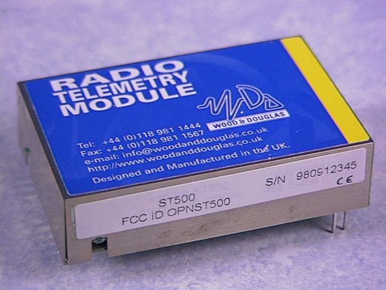
OPNST500ST500 Transmitter
Wood & Douglas Ltd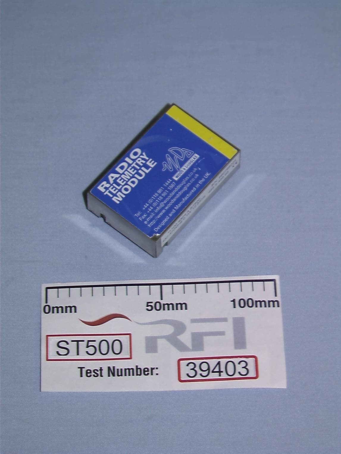
Click to zoom
Application Details
- Equipment Class
- TNB - Licensed Non-Broadcast Station Transmitter
- Date of Grant
- Feb 01, 2000
- Application Purpose
- Original Equipment
- Date of Application
- Sep 09, 1999
- Equipment Note
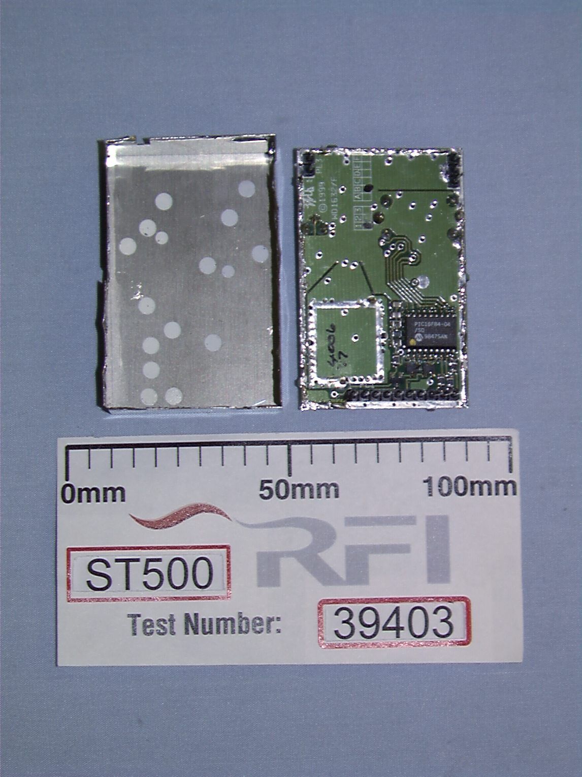
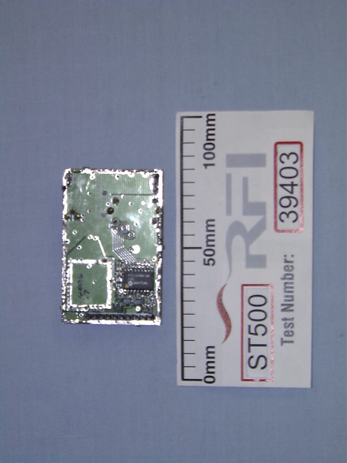
- ST500 Transmitter
- Frequency Range
- 430.00000000 - 470.00000000
- Company
- Wood & Douglas Ltd
- Country
- United Kingdom
Documents & Files
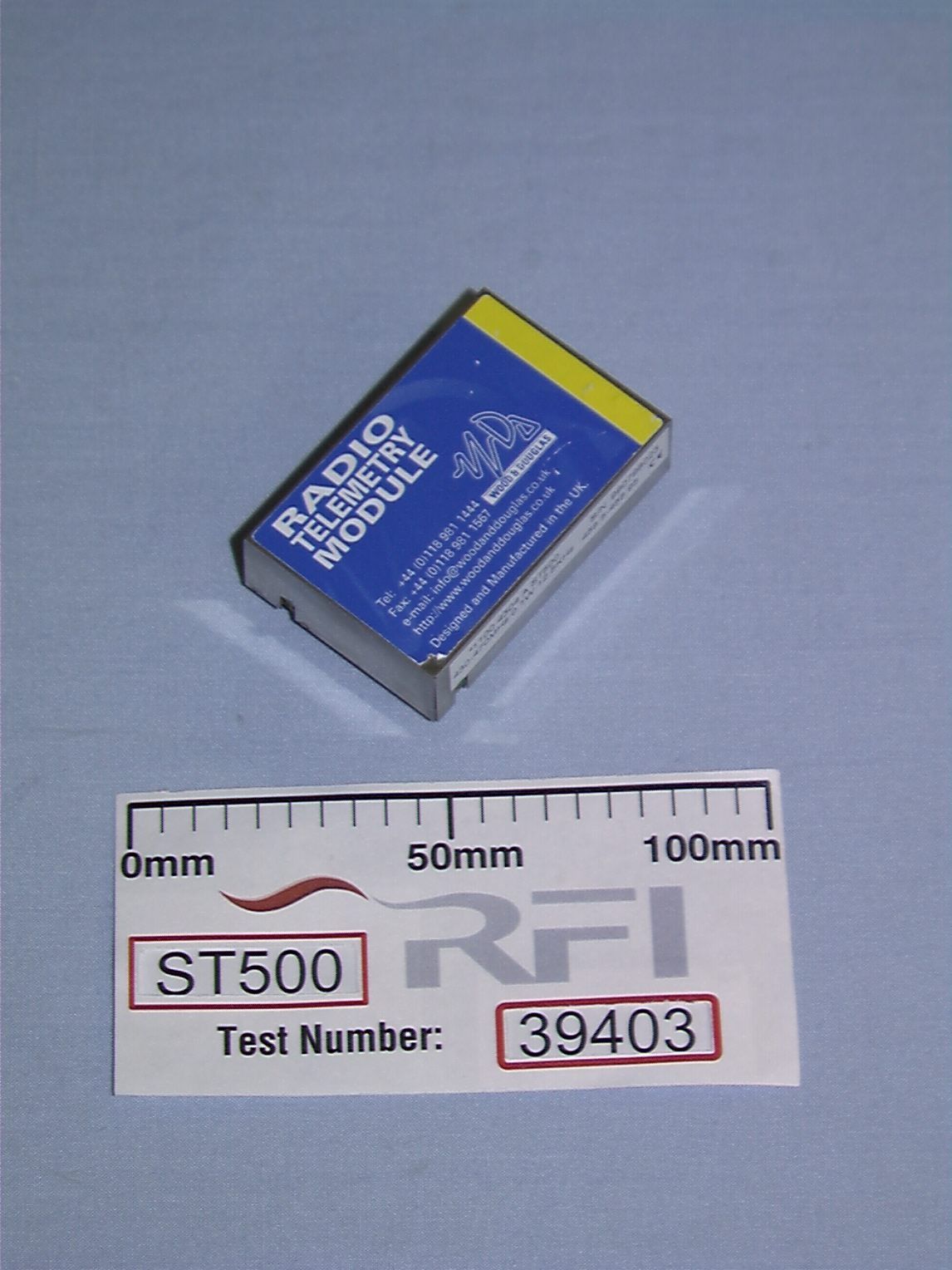
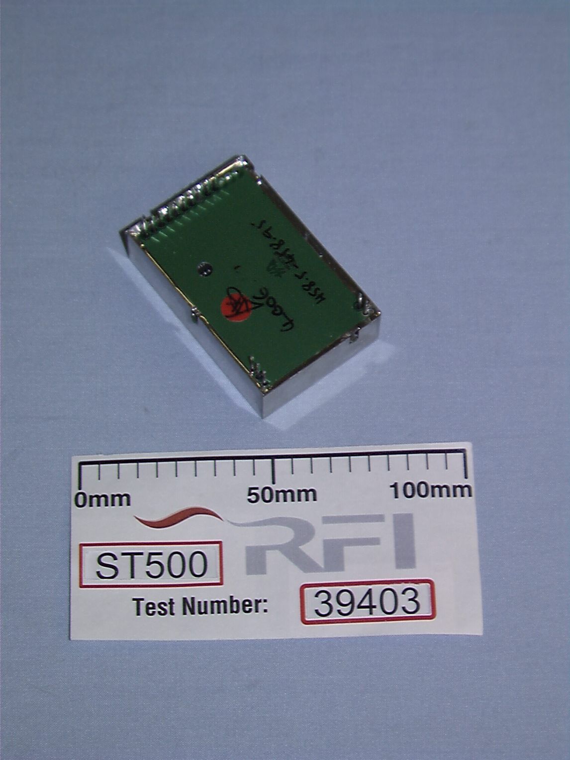
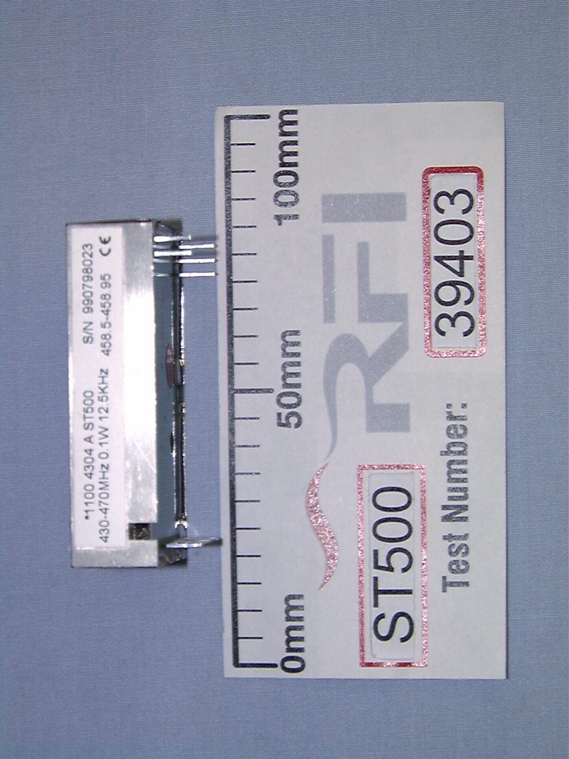
Document Text
Text extracted from the exhibit documents filed with the FCC. Open a document above to read the original.
Users Manual
ST500 TRANSMITTER TECHNICAL MANUAL (1891 1210) © Copyright Wood & Douglas Ltd 1998 version: 1.0 issue: November 1998 LATTICE HOUSE BAUGHURST ROAD TADLEY HAMPSHIRE UK RG26 5LP Tel: +44 (0)118 981 1444Fax:+44 (0)118 981 1567 1.0/November 19981891 1210 Contents Section 1 An overview.................................................5 1.1 GENERAL DESCRIPTION...................................6 Section 2 Operation...................................................7 2.1 USER CONNECTIONS......................................7 Section 3 Technical description.........................................9 3.1 POWER SUPPLY..........................................9 3.2 INPUT INTERFACE.........................................9 3.3 MODULATION STAGE......................................9 3.4 RADIO FREQUENCY STAGE................................10 3.5 FREQUENCY PROGRAMMING..............................14 Section 4 Technical specifications......................................19 DRAWINGS WS1494/XX7GENERAL ARRANGEMENT FOR ST500 WD1632/001CIRCUIT DIAGRAM FOR ST500 WD1632/XX2COMPONENT OVERLAY FOR ST500 (Sheet 1 of 3) WD1632/XX2COMPONENT OVERLAY FOR ST500 (Sheet 2 of 3) WD1632/XX2COMPONENT OVERLAY FOR ST500 (Sheet 3 of 3) C WD632 00ITEM LIST FOR LEADED COMPONENTS FOR ST500 A SM1632 00ITEM LIST FOR SURFACE MOUNT COMPONENTS FOR ST500 1891 12101.0/November 1998 5 1.0/November 19981891 1210 Section 1 An overview Wood & Douglas are an independent UK company dedicated to the design and manufacture of high quality RF designs for the telemetry, security, broadcast and video markets world-wide. The information given in this manual is Copyright Wood & Douglas and is provided to the original purchaser for the purposes of operation and routine maintenance. The contents of this manual must not be disclosed to any third party, nor may the purchaser make additional copies of the manual or store the information given on any electronic retrieval or mass storage system. The company reserves the right to amend or change specifications of its products without prior notice in accordance with the company policy of continued product improvement. NOTE: This device complies with Part 15 of the FCC Rules. Operation is subject to the condition that this device does not cause harmful interference. The unit is labelled with a serial number label as shown below: ST500 31980912345 FCC ID ABCST500 CECE where:990912345 is the serial number of the unit containing the date code for September 1998 ABC is the Wood & Douglas Ltd FCC code 6 1891 12101.0/November 1998 1.1 GENERAL DESCRIPTION The ST500 can be configured for analogue or digital operation and is available in the frequency range of 405 - 470MHz with a 12.5kHz channel spacing. The transmitter requires a nominal 12 volt DC supply connected via PL7. However the unit will function correctly within the limits of +6.0V to +14.0V. The output power of the transmitter is normally preset to 100mW nominal. The ST500 is intended to fit into OEM equipment housing by means of the three connectors which protrude through the base of the unit. 7 1.0/November 19981891 1210 Section 2 Operation 2.1 USER CONNECTIONS Connection to the ST500 transmitter is made via three headers, PL1, PL2 and PL3, which plug directly into the user's own equipment. The location of these connectors is shown in the General Arrangement drawing given at the back of this manual. The details of these three connectors are detailed below: PINNAMEFUNCTIONREMARKS 10V0 voltscommon ground 2bTbXbEtransmit enableo/c = transmitter disabled LOW <+0.8V = transmitter enabled 1KÙ nom. internal pull-up to +Vin 3DIGITAL I/Pdata input0/+3V to 0/+12V, DC-coupled 4ANALOGUE I/Pdata input300mV to 5V p-p, AC-coupled 5+5V O/P+5V supply output50mA max. current drain 6RS232 I/Pserial programming input If not used leave un-connected or ground. (refer to section 3.5 for details) 70V0 voltscommon ground 8RB1 parallel frequency select internal pull-up to +5V, active low (refer to section 3.5.4 for details) 9RB2 10RB3 Connector PL1 pin detail 8 1891 12101.0/November 1998 PINNAMEFUNCTIONREMARKS 10V0 voltscommon ground 2RF O/PRF output50 ohms output 30V0 voltscommon ground Connector PL2 pin detail PINNAMEFUNCTIONREMARKS 1+VINpositive supply+6.0V to +14.0V 20V0 voltscommon ground Connector PL3 pin detail 9 1.0/November 19981891 1210 Section 3 Technical description Refer to the circuit diagram WD1632 at the rear of this manual. 3.1 POWER SUPPLY DC power is connected to the transmitter module via PL3. The positive side of the supply is fed to TR2 which acts as a series switch; when PL1 pin 2 is connected to 0V to enable the transmitter then base current flows to TR2 via D6 and R54 and turns TR2 on. The output from the collector of TR2 (‘+Vraw’) is fed to dual operational amplifier IC4, to TR3 collector (via chokes L5 and L6) and also to voltage regulator IC2. This regulator provides a stable output of nominally +5V which is used to power all the remaining sections of the transmitter (apart from IC7) either directly or via R-C decoupling networks. 3.2 INPUT INTERFACE When the transmitter is to be used with an analogue modulation input then this input is fed from PL1 pin 4 via R2 and C2 to RV1 in the feedback network around IC1a. RV1 acts as an analogue gain control. When the transmitter is to be used with a digital modulation input then this input is fed from PL1 pin 3 via R1 to RV1 in the feedback network around IC1a. RV1 is set mid-way in this application such that it has no effect; IC1a then functions as a comparator and produces an output which swings between approximately +0.7V and +4.3V depending on whether the digital input is low or high. These output levels are well-defined and result in the modulation level being independent of the logic levels at the input to the transmitter. 3.3 MODULATION STAGE The output from IC1a is fed to a low-pass filter built around IC1b. This restricts the modulation bandwidth such that adjacent channel power levels are kept within s…
Text truncated - open the document above for the full version.
Test Report
Radio Frequency Investigation Ltd, Ewhurst Park, Ramsdell, Basingstoke, Hampshire, RG26 5RQ, ENGLAND. Tel: +44 (0) 1256 851193 Fax: +44 (0) 1256 851192 Registered in England, No. 211 7901. Registered Office: Ewhurst Park, Ramsdell, Basingstoke, Hampshire RG26 5RQ TESTING 0644 TEST REPORT FROM RADIO FREQUENCY INVESTIGATION LTD. Test Of: Wood & Douglas Ltd ST500 Transmitter To: FCC Part 90:1998 Test Report Serial No: RFI/EMCB2/RP39403B This Test Report supersedes RFI Test Report No.: RFI/EMCB1/RP39403B This Test Report Is Issued Under The Authority Of Brian Watson Technical Director: Checked By: Tested By:Release Version No: PDF01 Issue Date: 2 September 1999Test Date: 27 July 1999 This report is issued in Adobe Acrobat portable document format (PDF). It is only a valid copy of the report if it is being viewed in PDF format with the following security options not allowed: Changing the document, Selecting text and graphics, Adding or changing notes and form fields. Furthermore, the date of creation must match the issue date stated above. This report may be copied in full. RADIO FREQUENCY INVESTIGATION LTD.TEST REPORT S.No: RFI/EMCB2/RP39403B EMC DepartmentPage 2 of 46 Issue Date: 2 September 1999 Test Of:Wood & Douglas Ltd ST500 Transmitter To:FCC Part 90:1998 This page has been left intentionally blank. RADIO FREQUENCY INVESTIGATION LTD.TEST REPORT S.No: RFI/EMCB2/RP39403B EMC DepartmentPage 3 of 46 Issue Date: 2 September 1999 Test Of:Wood & Douglas Ltd ST500 Transmitter To:FCC Part 90:1998 Table of Contents 1. Client Information......................................................................................................4 2. Equipment Under Test (EUT).....................................................................................5 3. Test Specification, Methods And Procedures..........................................................7 4. Deviations From The Test Specification...................................................................8 5. Operation Of The EUT During Testing......................................................................9 6. Summary Of Test Results........................................................................................10 7. Measurements, Examinations And Derived Results..............................................11 8. Measurement Uncertainty........................................................................................33 Appendix 1. Test Equipment Used...............................................................................34 Appendix 2. Measurement Methods............................................................................35 Appendix 3. Test Configuration Drawings..................................................................39 Appendix 4. Graphical Test Results............................................................................42 Appendix 5. Photographs of EUT.................................................................................45 This Test Report supersedes RFI Test Report No.: RFI/EMCB1/RP39403B. RADIO FREQUENCY INVESTIGATION LTD.TEST REPORT S.No: RFI/EMCB2/RP39403B EMC DepartmentPage 4 of 46 Issue Date: 2 September 1999 Test Of:Wood & Douglas Ltd ST500 Transmitter To:FCC Part 90:1998 1. Client Information Company Name: Wood & Douglas Ltd Address: Lattice House Baughurst Basingstoke Hants RG26 5LP Contact Name: Mr A Stickland RADIO FREQUENCY INVESTIGATION LTD.TEST REPORT S.No: RFI/EMCB2/RP39403B EMC DepartmentPage 5 of 46 Issue Date: 2 September 1999 Test Of:Wood & Douglas Ltd ST500 Transmitter To:FCC Part 90:1998 2. Equipment Under Test (EUT) The following information (with the exception of the Date of Receipt) has been supplied by the client: 2.1. Identification Of Equipment Under Test (EUT) Brand Name: Wood & Douglas Ltd Model Name or Number: ST500 Unique Type Identification: ST500 31 Serial Number: 990798023 Country of Manufacture: UK FCC ID Number: Awaiting Certification from the FCC Date of Receipt: 27 July 1999 2.2. Description Of EUT The equipment under test is a synthesised 100 mW transmitter with 12.5 kHz channel spacing for telemetry use. 2.3. Modifications Incorporated In EUT None stated by client. 2.4. Additional Information Related To Testing Power Supply Requirement: DC supply of 9 V (customer supplied) Intended Operating Environment: Commercial Weight: 0.03 kg Dimensions: 60 mm x 40 mm x 20 mm (including pins) Interface Ports: 10 pin connector for I/O 2 pin connector for power 3 pin connector for RF RADIO FREQUENCY INVESTIGATION LTD.TEST REPORT S.No: RFI/EMCB2/RP39403B EMC DepartmentPage 6 of 46 Issue Date: 2 September 1999 Test Of:Wood & Douglas Ltd ST500 Transmitter To:FCC Part 90:1998 2.5. Support Equipment The following support equipment was used to exercise the EUT during testing: Description: ST500 Test Jig Brand Name: Wood and Douglas Model Name or Number: None stated by client Serial Number: WD011 FCC ID Number: None stated by client Cable Length And Type: Not applicable (Direct Connection to the EUT) Connected to Port: Not applicable Description: Plug Top power supply Brand Name: Seung Jin Electronics Co Model Name or Number: SJ-1205D Serial Number: WD009 FCC ID Number: None stated by client Cable Length And Type: 1.5m Twin Connected to Port: DC Input Port to Test Jig RADIO FREQUENCY INVESTIGATION LTD.TEST REPORT S.No: RFI/EMCB2/RP39403B EMC DepartmentPage 7 of 46 Issue Date: 2 September 1999 Test Of:Wood & Douglas Ltd ST500 Transmitter To:FCC Part 90:1998 3. Test Specification, Methods And Procedures 3.1. Test Specification Reference: FCC Part 90: 1998 Title: Code of Federal Regulations, Part 90 (47CFR90) Private Land Mobile Radio Services Comments: A description of the test facility used for this test is on file with, and has been accepted by, the Federal Communications Commission as required by Section 2.948 of Federal Rules. Purpose of Test: To determine whether the equipment complied with the requirements of the specification for the purposes of certif…
Text truncated - open the document above for the full version.
Test Report
Radio Frequency Investigation Ltd, Ewhurst Park, Ramsdell, Basingstoke, Hampshire, RG26 5RQ, ENGLAND. Tel: +44 (0) 1256 851193 Fax: +44 (0) 1256 851192 Registered in England, No. 211 7901. Registered Office: Ewhurst Park, Ramsdell, Basingstoke, Hampshire RG26 5RQ TESTING 0644 SUPPLEMENTARY TEST REPORT FROM RADIO FREQUENCY INVESTIGATION LTD. Test Of: Wood & Douglas Ltd. ST500 Transmitter To: FCC Part 90:1998 Incorporating FCC Part 2:1998 Supplementary Test Report Serial No: RFI/EMCB1/RP39403C This Supplementary Test Report forms an addendum to RFI Test Report No.: RFI/EMCB2/RP39403B This Test Report Is Issued Under The Authority Of Brian Watson Technical Director: Checked By: Tested By: pp Release Version No: PDF01 Issue Date: 14 January 2000Test Date: 6 January and 7 January 2000 This report is issued in Adobe Acrobat portable document format (PDF). It is only a valid copy of the report if it is being viewed in PDF format with the following security options not allowed: Changing the document, Selecting text and graphics, Adding or changing notes and form fields. Furthermore, the date of creation must match the issue date stated above. This report may be copied in full. RADIO FREQUENCY INVESTIGATION LTD.SUPPLEMENTARY TEST REPORT S.No. RFI/EMCB1/RP39403C EMC DepartmentPage 2 of 28 Issue Date: 14 January 2000 Test Of:Wood & Douglas Ltd. ST500 Transmitter To:FCC Part 90:1998 Incorporating FCC Part 2:1998 This page has been left intentionally blank. RADIO FREQUENCY INVESTIGATION LTD.SUPPLEMENTARY TEST REPORT S.No. RFI/EMCB1/RP39403C EMC DepartmentPage 3 of 28 Issue Date: 14 January 2000 Test Of:Wood & Douglas Ltd. ST500 Transmitter To:FCC Part 90:1998 Incorporating FCC Part 2:1998 Table of Contents 1. Client Information......................................................................................................4 2. Equipment Under Test (EUT).....................................................................................5 3. Test Specification, Methods And Procedures..........................................................7 4. Deviations From The Test Specification...................................................................9 5. Operation Of The EUT During Testing....................................................................10 6. Summary Of Test Results........................................................................................11 7. Measurements, Examinations And Derived Results..............................................12 8. Measurement Uncertainty........................................................................................18 Appendix 1. Test Equipment Used...............................................................................19 Appendix 2. Measurement Methods............................................................................20 Appendix 3. Test Configuration Drawings..................................................................24 Appendix 4. Graphical Test Results............................................................................27 This Supplementary Test Report forms an addendum to RFI Test Report No.: RFI/EMCB2/RP39403B. RADIO FREQUENCY INVESTIGATION LTD.SUPPLEMENTARY TEST REPORT S.No. RFI/EMCB1/RP39403C EMC DepartmentPage 4 of 28 Issue Date: 14 January 2000 Test Of:Wood & Douglas Ltd. ST500 Transmitter To:FCC Part 90:1998 Incorporating FCC Part 2:1998 1. Client Information Company Name: Wood & Douglas Ltd. Address: Lattice House Baughurst Basingstoke Hants RG26 5LP Contact Name: Mr A Stickland. RADIO FREQUENCY INVESTIGATION LTD.SUPPLEMENTARY TEST REPORT S.No. RFI/EMCB1/RP39403C EMC DepartmentPage 5 of 28 Issue Date: 14 January 2000 Test Of:Wood & Douglas Ltd. ST500 Transmitter To:FCC Part 90:1998 Incorporating FCC Part 2:1998 2. Equipment Under Test (EUT) The following information (with the exception of the Date of Receipt) has been supplied by the client: 2.1. Identification Of Equipment Under Test (EUT) Brand Name: Wood & Douglas Ltd Model Name or Number: ST500 Unique Type Identification: ST500 31 Serial Number: 990798023 Country of Manufacture: UK FCC ID Number: Awaiting Certification from the FCC Date of Receipt: 27 July 1999 2.2. Description Of EUT The equipment under test is a synthesised 100 mW transmitter with 12.5 kHz channel spacing for telemetry use. 2.3. Modifications Incorporated In EUT None stated by client. 2.4. Additional Information Related To Testing Power Supply Requirement: DC supply of + 9 V (customer supplied) Intended Operating Environment: Commercial Weight: 0.03 kg Dimensions: 60 mm x 40 mm x 20 mm (including pins) Interface Ports: 10 pin connector for I/O 2 pin connector for power 3 pin connector for RF RADIO FREQUENCY INVESTIGATION LTD.SUPPLEMENTARY TEST REPORT S.No. RFI/EMCB1/RP39403C EMC DepartmentPage 6 of 28 Issue Date: 14 January 2000 Test Of:Wood & Douglas Ltd. ST500 Transmitter To:FCC Part 90:1998 Incorporating FCC Part 2:1998 2.5. Support Equipment The following support equipment was used to exercise the EUT during testing: Description: ST500 Test Jig Brand Name: Wood and Douglas Model Name or Number: None stated by client Serial Number: WD011 FCC ID Number: None stated by client Cable Length And Type: Not applicable (Direct Connection to the EUT) Connected to Port: Not applicable Description: Plug Top Power Supply Brand Name: Seung Jin Electronics Co Model Name or Number: SJ-1205D Serial Number: WD009 FCC ID Number: None stated by client Cable Length And Type: 1.5m Twin Connected to Port: DC Input Port to Test Jig RADIO FREQUENCY INVESTIGATION LTD.SUPPLEMENTARY TEST REPORT S.No. RFI/EMCB1/RP39403C EMC DepartmentPage 7 of 28 Issue Date: 14 January 2000 Test Of:Wood & Douglas Ltd. ST500 Transmitter To:FCC Part 90:1998 Incorporating FCC Part 2:1998 3. Test Specification, Methods And Procedures 3.1. Test Specification Reference: FCC Part 90: 1998 and FCC Part 2: 1998 Title: Code of Federal Regulations, Part 90 (47CFR90) Private Land Mobile Radio Services Comments: A descriptio…
Text truncated - open the document above for the full version.
Contact Information
Applicant
Andrew Stickland(Mr)
*44 118 981 1444Fax: *44 118 981 1567
Technical Contact
Radio Frequency Investigation LtdNick G COBB
[email protected]+44 1256 855472
Ewhurst Park, · Basingstoke · United Kingdom
Technical Specifications
| # | Rule Parts | Frequency Range | Power Output | Emission | Tolerance |
|---|---|---|---|---|---|
| 3 | 9 | 430 MHz - 470 MHz | 10.00 mW | 12K5F3D | 2.5 ppm |
Other Applications from Wood & Douglas Ltd
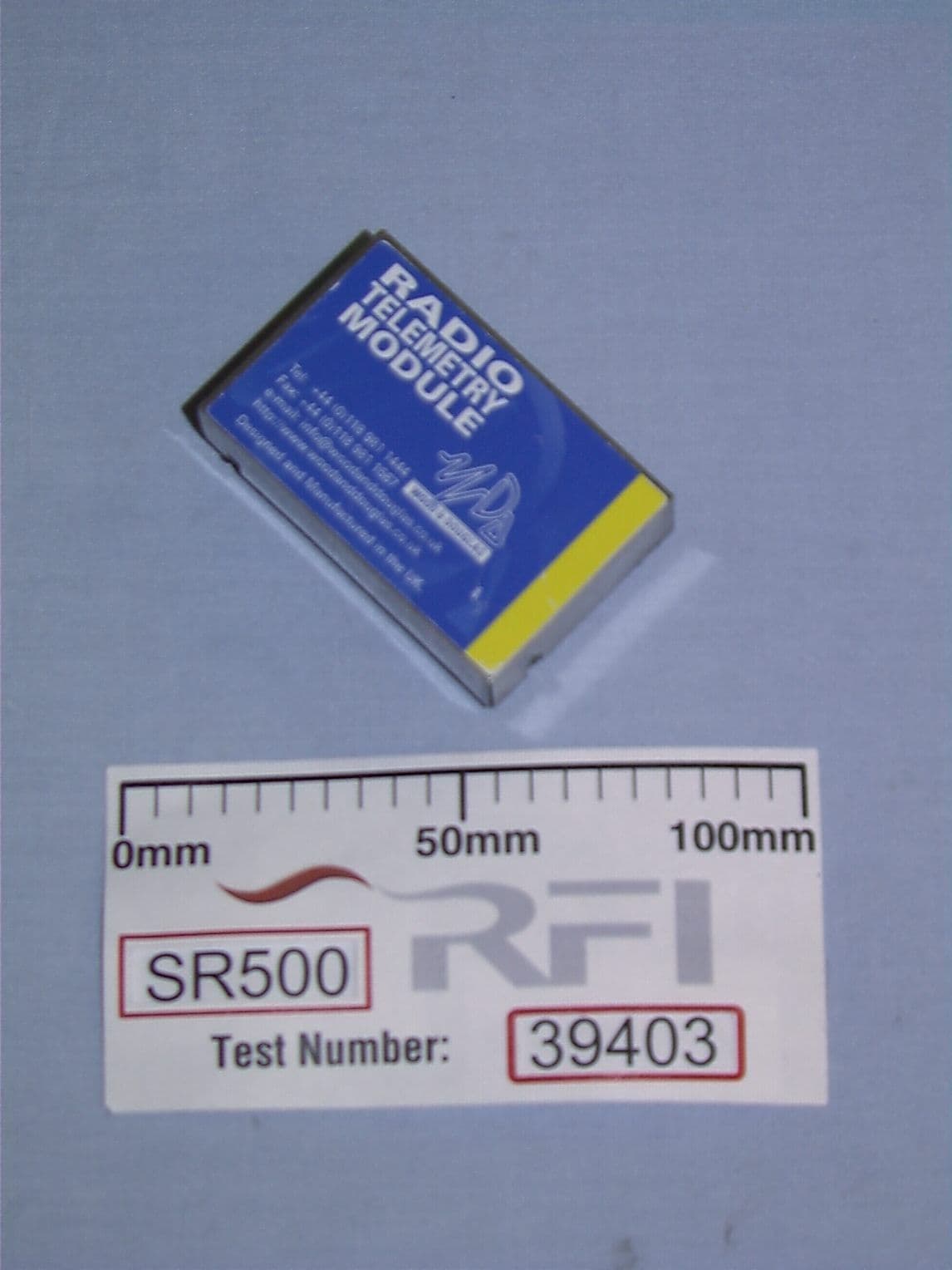
OPNSR500
Feb 01, 2000SR500 Receiver
Equipment Class
DXC - Part 15 Low Power Transceiver, Rx Certified