OPRM08001VoyagerBlue24
Orb Information Technology Ltd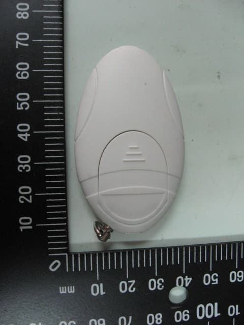
Click to zoom
Application Details
- Equipment Class
- DXT - Part 15 Low Power Transceiver, Rx Verified
- Date of Grant
- Oct 24, 2012
- Application Purpose
- Original Equipment
- Date of Application
- Oct 24, 2012
- Equipment Note
- VoyagerBlue24
- Frequency Range
- 2403.00000000 - 2451.00000000
- Country
- United Kingdom
Documents & Files
Document Text
Text extracted from the exhibit documents filed with the FCC. Open a document above to read the original.
Users Manual
Base Unit Setting button OVERVIEW SPECIFICATION OVERVIEW GETTING STARTED SPECIFICATION SUGGESTED SETTING PLACE Base Unit Tag Unit 1. Insert batteries in to base and the tag unit in accordance with the battery installation Instructions illustrated. BE SURE TO SLIDE TAG UNIT BATTERY BETWEEN THE UPPER AND LOWER BATTERY CONTACTS. IMPORTANT NOTE: Placing battery on top of contact and closing the lid will cause damage to the battery terminal and will invalidate the warranty. Slide out the battery cover. Insert batteries (included) followingthe polarity markings in the batterycompartment.Close the battery cover back to its place as shown. Tag Unit - Base unit 2. Switch the power button of the base unit and the tag unit to the "ON" position. Connection between both units may take up to 16 seconds. Once connected the device is ready for use and is set to sensitive mode.3. Press the setting button to set the desired alert range. The default setting is: High sensitivity RED LED - Medium Sensitivity ORANGE LED – Low Sensitivity GREEN LED. To select the sensitivity mode: hold setting button for 3 seconds. The status LED will change colour from Red (High sensitivity ) to orange (medium sensitivity) to Green (low sensitivity) to Red (high sensitivity ). Simply release the button when the desired alert sesnsitivity colour is illuminated.4. For more detailed information on "How to tips" and where we recommend setting the shield and proximity alarm device see separate page on reverse of VoyagerBlue24 Picture Manual.Or visit www.voyagerblue.co.uk. ALWAYS REMOVE BEFORE INSPECTION BY AN AUTHORIZED PERSON. If storing inside a wallet or purse ensure the shielding device is on the outside of the credit / ID card to be protected with the non protected side closest to your person. Attach the base unit to a garment or article of clothing which you are not going to take off whilst the device is in use. Page 1 1 1 2 3 Status LED Power switch Battery cover Power ON/OFF Show the signal synchronous status between Base and Tag unit VoyagerBlue24 USER MANUAL VoyagerBlue24 is a digital wireless device with proximity alarm and e-Pickpocket shielding capabilities. It has been specifically designed to HELP PREVENT the theft of your personal identityfrom contactless technology documents or the loss of your essential documents such as: Passports,ePassports, credit and ID cards.There are three "Alarm / sensitivity modes" each can be individuallyselected as: High, Medium, or Low from the base unit. Once the tag is out of range, the base unit will trigger an alarm at 95db Front Back 1 2 3 4 5 6 1 2 3 4 5 6 Key Chain Speaker Status LED Power switchBattery cover Power ON/OFF Shows the signal status and range setting conditionSound output Set desired alert range (Default is set to Near range) Front Beep Sound (at 10cm/3.9inch) Model Name Function Alarm Sensitivity Devices Battery TypeBattery Life Time with StandbyDimension (L/W/H) VoyagerBlue24 Alert Base(M08) Tag(S09) CR2032x1 CR2016x1 95db ± 3(db) No Sound 60 days ( with 8 hours/day) 50x30x3mm Medium(Orange LED) : 10±3m/32±10ft High(Red LED) : 5±2m/16±6ft Low(Green LED) : 20±6m/64±20ft 61.5x36x11.6mm 2.42x1.42x0.46inch 1.96x1.18x0.12inch 1 2 CR2016 - Tag unit RANGE ALERT If the Base unit makes a high frequency beeping tone, it means the distance between the Base unitand the Tag unit is over the selected sensitivity range. Over the selected sensitivity range anaudible 95dB alarm will sound Once both units come back in to range the alarm beep will stop sounding. Alarm fromBase unit When most sensitive mode is selected care must be taken to avoid signal blocking by the human body. It will help to set the transmitter tag and alarm base unit on the same side of the body. 2 3 Back Page 2 VoyagerBlue24 USER MANUAL Important Notes:1. When stored inside the wallet as illustrated. THE WALLET MUST NOT BE STORED IN BACK POCKET AS THIS COULD RESULT IN DAMAGE TO THE TAG UNIT INVALIDATING THE WARRANTY. 2. When placing the Tag unit into a wallet and then inserting into a front pocket always locate Base unit on to the same side of your person selecting the sensitivity which best suits the environment and your needs. CR2032 The side facing upwards The side facing upwards 3 1 2 3 1 2 3 Frequency / Channel Plan 2.403GHz~2.451GHz / Channel Space : 250KHz, Total 193 channels FREQUENT ASKED QUESTIONS Q. What conditions can cause false alarms?A. False alarms are caused by following reasons: 1. Low battery power will cause unpredictable behavior. 2. Unit has been blocked by human body, or Other obstruction.Q. Why is the range alarm distance not consistent?A. Because radio signal strength and signal refection are affected by the environment. Users may need to adjust range to compensate for environment factors. Page 3 Page 4 LOW BATTERY When either the base or Tag unit are under low battery power status the Base unit sounds : • One beep every two minutes indicating a Base unit low power status. • Two beeps every two minutes indicating a Tag unit low power status.Important: Under low battery conditions the base unit may emit abnormal / false alarms. OUT OF RANGE / LOST SIGNAL a.) The base unit beeps and the signal LED blinks for 20 seconds when out of range or an item becomes lost. After this 20 second period the base unit will automatically enter a temporary sleep mode.b.) The base unit beeps for a period of 20 seconds every two minutes when in the Out Of Range / Lost Signal (Sleep) mode. This is a reminder for the user to switch the unit off in order to conserve base unit power and battery life. c.) Once you are aware of a lost or out of range status ensure you switch the base unit off to conserve battery power.Once the signal range as been resumed or the lost item recovered, re-arm the base and tag unit by following the power on procedure described in this manual. If preferred, the base unit can be left switched on when an alarm status is sounded as the base unit will stop sounding when the Tag unit i…
Text truncated - open the document above for the full version.
Cover Letter(s)
910805 1 Orb Information Technology Ltd Compliance Certification Services Certification Division 561F Monterey Road Morgan Hill, CA 95037 To whom it may concern: We, the undersigned, hereby authorize ELECTRONICS TESTING CENTER, TAIWAN, to act on our behalf in all manners relating to application for equipment authorization, including signing of all documents relating to these matters. Any and all acts carried out by ELECTRONICS TESTING CENTER, TAIWAN on our behalf shall have the same effect as acts of our own. We, the undersigned, hereby certify that we are not subject to a denial of federal benefits, that includes FCC benefits, pursuant to Section 5301 of the Anti-Drug Abuse Act of 1988, 21 U.S.C. 853(a). In authorizing ELECTRONICS TESTING CENTER, TAIWAN as our agent, we still recognize that we are responsible to: a) comply with the relevant provisions of the certification program; b) make all necessary arrangements for the conduct of the evaluation, including provision for examining documentation and access to all areas, records (including internal audit reports) and personnel for the purposes of evaluation (e.g. testing, inspection, assessment, surveillance, reassessment) and resolution of complaints; c) make claims regarding certification only in respect of the scope for which certification has been granted; d) do not use our product certification in such a manner as to bring the Certification Division into disrepute and not make any statement regarding our product certification which the Certification Division may consider misleading or unauthorized;
External Photos
ETC Report No. : 12-08-RBF-003-04 Sheet 1 of 5 Sheets FCC ID.: OPRM08001 Rev. No 2.0 CONSTRUCTED PHOTOS of EUT 1. 2. ETC Report No. : 12-08-RBF-003-04 Sheet 2 of 5 Sheets FCC ID.: OPRM08001 Rev. No 2.0 CONSTRUCTED PHOTOS of EUT 3. 4. ETC Report No. : 12-08-RBF-003-04 Sheet 3 of 5 Sheets FCC ID.: OPRM08001 Rev. No 2.0 CONSTRUCTED PHOTOS of EUT 5. 6.
ID Label/Location Info
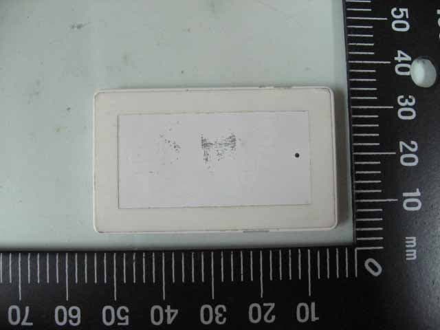
22*5 mm FCC ID: OPRM08001
Internal Photos
ETC Report No. : 12-08-RBF-003-04 Sheet 4 of 5 Sheets FCC ID.: OPRM08001 Rev. No 2.0 CONSTRUCTED PHOTOS of EUT 7. 8. ETC Report No. : 12-08-RBF-003-04 Sheet 5 of 5 Sheets FCC ID.: OPRM08001 Rev. No 2.0 CONSTRUCTED PHOTOS of EUT 9.
Test Report
Rev. No 2.0 FCC Part 15 EMI TEST REPORT of E.U.T. : VoyagerBlue24 MODEL : M08 FCC ID. : OPRM08001 Frequency Range : 2403MHz~2451MHz for APPLICANT : Orb Information Technology Ltd ADDRESS : The Old Coach House, Llanfaelog, Ty-Creos, Anglesey LL63 5SS, UK. Test Performed by ELECTRONICS TESTING CENTER, TAIWAN NO. 34. LIN 5, DINGFU VIL., LINKOU DIST., NEW TAIPEI CITY, TAIWAN, 24442, R.O.C. TEL : (02)26023052 FAX: (02)26010910 http : // www.etc.org.tw; e-mail : [email protected] Report Number : 12-08-RBF-003-04 ETC Report No. : 12-08-RBF-003-04 FCC ID. : OPRM08001 Rev. No 2.0 TEST REPORT CERTIFICATION Applicant : Orb Information Technology Ltd 4F., No.11, Lane. 125, Sec. 1, Guoguang Rd., Dali Dist., Taichung City 41262, Taiwan (R.O.C.) Manufacturer : Orb Information Technology Ltd 4F., No.11, Lane. 125, Sec. 1, Guoguang Rd., Dali Dist., Taichung City 41262, Taiwan (R.O.C.) Description of EUT a) Type of EUT : VoyagerBlue24 b) Trade Name : Orb IT Ltd c) Model No. : M08 d) Power Supply : DC 3V Battery e) Frequency Range : 2403MHz~2451MHz Regulation Applied : FCC Rules and Regulations Part 15 Subpart C I HEREBY CERTIFY THAT: The data shown in this report were made in accordance with the procedures given in ANSI C63.4, and the energy emitted by the device was founded to be within the limits applicable. I assume full responsibility for accuracy and completeness of these data. Note: 1. The result of the testing report relate only to the item tested. 2. The testing report shall not be reproduced expect in full, without the written approval of ETC. Summary of Tests Test Results Radiated Emission Pass Conducted Emission Pass Band Edge Requirement Pass ETC Report No. : 12-08-RBF-003-04 FCC ID. : OPRM08001 Rev. No 2.0 Date Test Item Received : Aug. 08, 2012 Date Test Campaign Completed : Aug. 29, 2012 Date of Issue : Sep. 20, 2012 Test Engineer : ( Vincent Chang, Engineer ) Approve & Authorized Signer : S. S. Liou, Section Manager EMC Dept. II of ELECTRONICS TESTING CENTER, TAIWAN ETC Report No. : 12-08-RBF-003-04 FCC ID. : OPRM08001 Rev. No 2.0 Table of Contents Page 1 GENERAL INFORMATION ...................................................................................................... 1 1.1 Product Description...................................................................................................................... 1 1.2 Characteristics of Device ............................................................................................................. 1 1.3 Test Methodology ........................................................................................................................ 1 1.4 Test Facility.................................................................................................................................. 1 2 PROVISIONS APPLICABLE ..................................................................................................... 2 2.1 Definition ..................................................................................................................................... 2 2.2 Requirement for Compliance ....................................................................................................... 3 2.3 Restricted Bands of Operation ..................................................................................................... 5 2.4 Labeling Requirement .................................................................................................................. 5 2.5 User Information .......................................................................................................................... 6 3. SYSTEM TEST CONFIGURATION ......................................................................................... 7 3.1 Justification .................................................................................................................................. 7 3.2 Devices for Tested System........................................................................................................... 7 4 RADIATED EMISSION MEASUREMENT.............................................................................. 8 4.1 Applicable Standard ..................................................................................................................... 8 4.2 Measurement Procedure............................................................................................................... 8 4.3 Measuring Instrument ................................................................................................................ 11 4.4 Radiated Emission Data ............................................................................................................. 12 4.4.1 RF Portion ......................................................................................................................................... 12 4.4.2 Other Emissions ................................................................................................................................. 16 4.5 Field Strength Calculation ......................................................................................................... 16 4.6 Photos of Radiation Measuring Setup........................................................................................ 17 5 CONDUCTED EMISSION MEASUREMENT ....................................................................... 18 5.1 Description ................................................................................................................................. 18 6 ANTENNA REQUIREMENT ................................................................................................... 19 6.1 Standard Applicable ................................................................................................................... 19 6.2 Antenna Construction................................................................................................................. 19 7 BAND EDGES MEASUREMENT ....…
Text truncated - open the document above for the full version.
Test Setup Photos
ETC Report No. : 12-08-RBF-003-04 Sheet 17 of 23 Sheets FCC ID.: OPRM08001 Rev. No 2.0 4.6 Photos of Radiation Measuring Setup
Contact Information
Applicant
Andre Kay(Managing Director)
Test Firm
Electronics Testing Center, TaiwanWill Yauo
Technical Specifications
| # | Rule Parts | Frequency Range | Power Output |
|---|---|---|---|
| 1 | 15C | 2.40 GHz - 2.45 GHz | - |
Other Applications from Orb Information Technology Ltd
OPRS09001
Oct 24, 2012VoyagerBlue24
Equipment Class
DXT - Part 15 Low Power Transceiver, Rx Verified