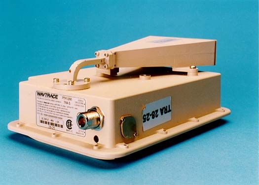
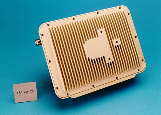
OPU-PTM1000-28PTM1000 (TRA 1000S, FE, 1.4, 28GHz [S1])
Wavtrace, Inc.![PTM1000 (TRA 1000S, FE, 1.4, 28GHz [S1]) - FCC ID OPU-PTM1000-28 - Wavtrace, Inc.](/_next/image?url=%2Fapi%2Ffiles%2Fs2%2Fproducts%2FOPU-PTM1000-28%2Fd47624ff1ba8ac4c_0.jpg&w=3840&q=75)
Click to zoom
Application Details
- Equipment Class
- TNB - Licensed Non-Broadcast Station Transmitter
- Date of Grant
- Jan 30, 2000
- Application Purpose
- Original Equipment
- Date of Application
- Sep 16, 1999
- Equipment Note
- PTM1000 (TRA 1000S, FE, 1.4, 28GHz [S1])
- Frequency Range
- 27512.50000000 - 28337.50000000
- Company
- Wavtrace, Inc.
- Country
- United States
Documents & Files
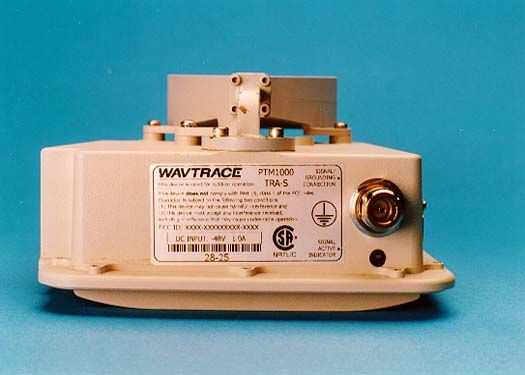
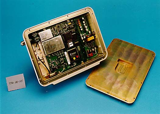
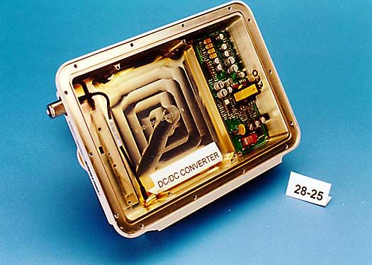
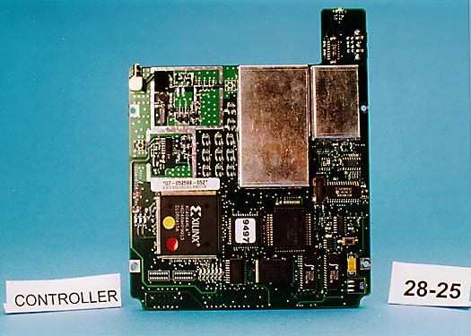
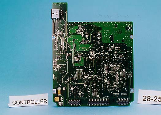
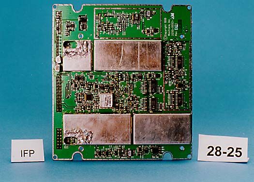
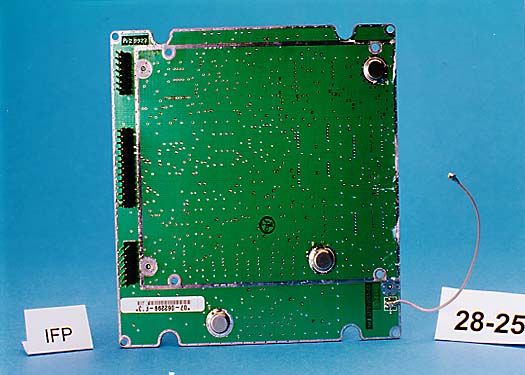
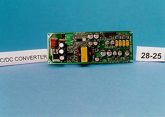
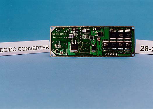
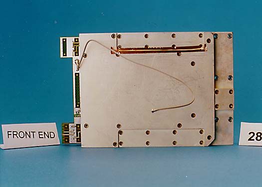
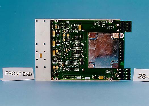
Document Text
Text extracted from the exhibit documents filed with the FCC. Open a document above to read the original.
Users Manual
Wavtrace™ PTM 1000 Operations and Maintenance Manual Chapter 2System Description This Chapter describes the following: •System Overview, page 12 •Hub – Remote Comparison, page 13 •System Connections, page 15 •Hub Indoor Unit (IDU), page 17 •Hub Outdoor Unit (ODU), page 23 •Remote Indoor Unit (IDU), page 26 •Remote Outdoor Unit (ODU), page 30 12Draft: 8/13PTM 1000 Operations and Maintenance Manual System Overview The PTM 1000 broadband wireless system consists of two primary elements : a hub (indoor unit and outdoor unit) and multiple remotes (indoor and outdoor units), as shown in Figure 2. Figure 2 PTM 1000 Broadband Wireless System The hub is equivalent to a base station in cellular terminology. The hub is composed of an indoor unit (IDU) and an outdoor unit (ODU). The hub IDU, which consists of electronic equipment housed in a stand-alone cabinet or in a free-standing rack, is placed within an office building or other structure. The hub ODU is placed on top of the structure where the IDU is housed, and can be as much as 1000 feet away from the IDU. It consists of multiple horn or dish antennas with their associated interface electronics and mounting frames. The remote is composed of an indoor unit (IDU) and an outdoor unit (ODU). The remote IDU is placed within an office building or other interior structure. The remote IDU is composed of electronic equipment housed in a standalone cabinet or in a free-standing rack. Chapter 2: System DescriptionDraft: 8/1313 The remote ODU is placed on top of the office building or other external structure, up to 1000 feet. The remote ODU can also be placed indoors. The remote ODU consists of a single parabolic antenna, its associated interface electronics and mounting frame. Hub – Remote Comparison The remote IDU is similar to the hub IDU. The following paragraphs compare their capabilities: •The remote is a single antenna/single airlink device. The remote performs the same types of functions as the hub, using a single airlink time slot. The hub has multiple time slots, one slot per remote. •The remote antenna is a high gain parabolic device, which has a narrow beam. In comparison, the hub can also use antennas that are designed to cover a wider area. The remote uses the same RF transceiver electronics as the hub. Each remote is composed of a single transceiver and antenna. The hub can support as many as four remotes, with each containing a single transceiver and antenna. •The remote ODU does not require an outdoor distribution box (ODB), as does the hub. For the remote, the functions of the hub ODB are incorporated into the remote IDU. •The remote IDU is connected to the remote ODU via one coaxial cable, which transports IF frequencies between the IDU and the ODU. The coaxial cable is also used to deliver power from the IDU to the ODU. 14Draft: 8/13PTM 1000 Operations and Maintenance Manual •The PTM 1000 System requires "line of sight" between the hub antenna and remote antenna. For indoor mounting, the remote TRA must be placed near a window that maintains a line of sight to the hub. •Because the remote uses only one TRA for each remote IDU, the remote requires only one modem control function. Further, there is no need to frequency multiplex multiple IF signals onto the coaxial cable (there are no multiple IFs to multiplex). Unlike the hub, the remote does not require a separate IFD PCA. •Critical IFD PCA functions are carried over to the remote. The coax control channel from the hub IFD PCA is required to permit the remote to configure the TRA. The remote uses the same FM modem as the one used in the IFD PCA. The remote also uses the RSSI and cable compensation. •The remote IDU interfaces directly to the end customer equipment. Chapter 2: System DescriptionDraft: 8/1315 System Connections Hub Connections One hub IDU can support up to four outdoor frames (ODFs), with each ODF servicing a 90-degree quadrant. A pair of RG-8 coaxial cables run between the intermediate frequency distribution (IFD) printed circuit assemblies (PCAs) in the hub IDU and the outdoor distribution box (ODB) in the hub ODU, connecting the hub indoor unit to the outdoor unit. The two RG-8 coaxial cables provide an interface between the hub IDU and ODU. These cables transport intermediate frequencies (I/F) from the hub IDU to the ODU (forward), and from the hub ODU to the IDU (reverse). Power from the hub IDU is delivered to the ODU on both the forward link and reverse link cables. Note Transport from the hub to the remote is considered aforward transmission because the remote downloads in this direction. Transport from the remote to the hub is areversetransmission because the remote uploads in this direction. The hub interconnects and switches between two types of communication interfaces: •High speed wireless airlinks to multiple remotes •OC-3 links to wireline broadband networks Each remote unit interfaces to the hub through a single high speed airlink and provides one or more customer premise data ports for DS1 or Ethernet connection. 16Draft: 8/13PTM 1000 Operations and Maintenance Manual Remote Connection The remote network connection uses much less bandwidth than the hub’s OC3 interface. The remote may have a maximum of 11 DS1 ports at this time. The hub is the distribution point and there are multiple remotes for each hub, but traffic flow is referenced to the remote. The PTM 1000 System references the forwardlink as the RF path from the Service Provider’s network connection through the hub to the remote. The reverse link is data flow from the remote to the hub and to the Service Provider’s network. Note Transport from the hub to the remote is considered a forward link because the remote downloads in this direction. Transport from the remote to the hub is an reverse link because the remote uploads in this direction. Chapter 2: System DescriptionDraft: 8/1317 Hub Indoor Unit (IDU) Figure 3hub Indoor Unit (IDU) NoteThe hub IDU is shipped with printed circuit assemblies (PC…
Text truncated - open the document above for the full version.
Users Manual
Wavtrace™ PTM 1000 Operations and Maintenance Manual Chapter 4Installation and Alignment This Chapter describes the following: •Preparation, page 44 •Installing the Hub ODU, page 47 •Installing the Hub IDU, page 57 •Installing the Remote ODU, page 67 •Installing the RemoteIDU, page 68 •Remote Antenna Alignment, page 69 Perform the installation in the sequence presented in this Chapter. Refer to the site survey and the Grounding chapter of this manual for supporting information. 44Draft: 8/13PTM 1000 Operations and Maintenance Manual Preparation Communications Two-way radio communications are recommended between personnel: •hub ODU to hub IDU •remote ODU to remote IDU •remote antenna alignment Wiring Closet Recommendations Installation of the Wavtrace system covers most wiring closet concerns. Wavtrace recommends checking the following items: •Ground the racks properly. The racks provide a secondary ground for the system. •The connection terminals for field wiring of the –48 Vdc must be suitable for the wire gauges commonly used in the USA and Canada. Current-carrying conductors are required to be rated at least 125% of the equipment rating. •Ensure that the wiring closet meets all state, local and country building and wiring codes. •Ensure that all wiring closet doors have locks to prevent unauthorized access. •Ensure that the wiring closet floor is concrete. If distribution racks are used, bolt racks to the floor to prevent them from tipping over. •Ensure that ventilation in the wiring closet is adequate to maintain a temperature below 40 degrees centigrade (104 degrees Fahrenheit). •Guard against ventilation shutdown while the PTM 1000 system remains powered up. Otherwise, the equipment might shut down due to overheating. All of the following requirements must be met, where applicable: •Connect the equipment directly to the dc supply system protective earth electrode conductor. It can also be connected to a bonded jumper from a protective earth terminal bar or bus if it is connected to the dc supply system protective earth electrode. Chapter 4: InstallationDraft: 8/1345 •Locate the equipment in the same immediate area (e.g., adjacent cabinets) as any other equipment that has a connection between the protective earthed conductor of the same dc supply circuit and the protective earth conductor, and also the point of protective earth of the dc system. Do not earth-ground the dc system elsewhere. •Locate the dc supply source within the same premises as this equipment. •Do not use switching or disconnecting devices in the protective earthed circuit conductor between the dc source and the point of connection of the protective earth electrode conductor. Rack Requirements Rack Grounding Properly ground the rack to ensure that voltages induced into wiring by lightning or other disturbances are directed to ground. Rack Space Requirement Allow a minimum of 76 cm (30 in.) between the rack and any wall behind or in front of it. This space in front of and behind the system allows room for servicing. Rack Specifications •In the USA, use EIA Standard RS-310D: Racks, Panels, and Associated Equipment. •In countries other than the USA, use IEC Standard 297: Dimensions of Panels and Racks. •Use a rack that has the universal mounting rail hold pattern identified in IEC Standard 297. • Usearackthatismadeofsteel. •Use a rack that can be used as electrical grounding. 46Draft: 8/13PTM 1000 Operations and Maintenance Manual To ol s Weatherproofing Weatherize all connectors exposed to the elements. You will need the following materials: •Butyl tape •¾” Electrician’s tape •Cable ties (6”) Table 2: Required Installation Tools Required toolsHub ODU Hub IDU Remote ODU Remote IDU Open-end wrench set, 9/16"–3/4"XXXX Hex key set, 1/4"–3/8"X Flush cuttersXXX ODF alignment bracketX InclinometerX GPS testing deviceX #2 Philips screwdriverXX Std crimps for fuse holderX Chapter 4: InstallationDraft: 8/1347 Installing the Hub ODU Inspect and Verify the Equipment 1Verify that the equipment and hardware matches the packing list. 2Inspect the equipment for shipping damage. Install the ODF Mounting Bracket to the To wer M as t Install the bracket on the pipe in the general area of the azimuth. 1Place the outward side of the bracket toward the azimuth. 48Draft: 8/13PTM 1000 Operations and Maintenance Manual . Figure 16 ODF Mounting Bracket 2Wrap two U-bolts around the antenna mast and thread through the appropriate mounting bracket holes. 3Fasten with ½” nuts, flat washers and lock washers supplied. WarningWhen installing a hub ODU on a mast or tower, ensure that the unit is properly secured prior to lifting. If hoisting is required, use a tag line to maintain control of the ODF. To avoid injury, ensure that all personnel are clear of the area below the ODF. Note Do not completely tighten the ½” nuts. Secure snugly to hold in place. Chapter 4: InstallationDraft: 8/1349 Install the ODF 1Install the frame turnbuckle on the mounting bracket using ¼” socket nut and ¼” hex key wrench. 2Set the turnbuckle for mid range to allow fine adjustments in either direction. 3Install the ODF on the bracket using swivel nuts provided. (Do not tighten completely.) 4Install the final frame turnbuckle assembly to the ODF using ¼” socket nut and ¼” key wrench. 5If more than one frame is required to be installed on the antenna mast, an additional 31” of surface area must be provided on the mast per ODU assembly. Perform a quadrant alignment. . Figure 17 ODF and Turnbuckle Assembly 50Draft: 8/13PTM 1000 Operations and Maintenance Manual Perform a Quadrant Alignment Use the azimuth aiming bracket (from Wavtrace) to align the ODF. Figure 18 Azimuth Aiming Bracket on ODF 1Install two socket head cap screws into the desired position on the ODF. 2Place the azimuth aiming bracket keyhole over screws in the ODF, then slide the bracket against the narrow end of the keyhole. 3Using a digital compass, align sights to the azimuth bracket. 4Once the sights have be…
Text truncated - open the document above for the full version.
Users Manual
Wavtrace™ PTM 1000 Installation and Maintenance Manual Chapter 1Safety and Certification This Chapter describes the following: •Safety and Note Definitions, page 2 •Electrostatic Discharge (ESD) Warnings, page 3 •Moisture-Sensitive Device (MSD) Warnings, page 4 •Electrical Safety Guidelines, page 5 •Lifting Guidelines, page 8 •Certification, page 9 2 Draft: 12/8PTM 1000 Installation and Maintenance Manual Safety and Note Definitions This manual uses the following: Note Qualifies or presents important points about the subject matter that is being presented. ! ImportantAlerts the reader to critical information about the subject matter that is being presented. ! CautionAlerts the reader to actions that should be followed to prevent damage to a device, or to meet a necessary requirement. WarningAlerts the reader to the risk of severe personal injury. ESD WarningAlerts the reader to an electrostatic discharge (ESD) concern. Chapter 1: Safety and Certification Draft: 12/8 3 Electrostatic Discharge (ESD) Warnings What is ESD? ESD can be generated and stored in a person’s body through routine activity, forming a charge. If this static electric charge does not dissipate before the person handles electronic equipment, it can be discharged into equipment and cause damage to electrostatic-sensitive components. ESD damage can be catastrophic; more often it subtly degrades the performance of equipment over time. The following symbol in Figure 1 indicates that the unit is sensitive to electrostatic discharge. Figure 1 Figure 1ESD Symbol Prevention Observe the following precautions to prevent damage from ESD while handling electrostatic-static devices. •When handling electrostatic-sensitive devices, use a standard wrist strap and grounding wire. Connect the grounding wire securely to the equipment chassis, frame or ground. •When an electrostatic-sensitive device is not mounted, it must be stored in a sealed protective package approved for that purpose. The package should be clearly marked with an ESD warning and symbol. •When working on an electrostatic device work bench, a grounded dissipative workmat must be used on all work surfaces and the technician must wear the grounded wrist strap. 4 Draft: 12/8PTM 1000 Installation and Maintenance Manual Moisture-Sensitive Device (MSD) Warnings Some units and/or assemblies are shipped in vacuum-sealed packages to protect moisture-sensitive devices (MSDs). An MSD is a component in which moisture can accumulate and cause damage when the component is not powered or is not in use. After an MSD unit or assembly is removed from its vacuum-sealed package, the MSD must be kept in a dry place not susceptible to moisture. Chapter 1: Safety and Certification Draft: 12/8 5 Electrical Safety Guidelines Use the following electrical safety guidelines before installing the Hub or remote units. To avoid electrical shocks, burns or equipment damage, read and observe all warnings and cautions. In Case of an Electrical Accident If an electrical accident occurs: •Do not become a victim yourself. •Disconnect power to the system. •Send another person to get medical aid if possible. Otherwise, assess the condition of the victim and then call for help. Basic Electrical Safety Guidelines Use these guidelines when working with any electrical equipment: •Carefully examine your work area for possible hazards, such as moist floors, ungrounded power extension cables, and missing safety grounds. •Keep the area clear and dust-free during and after installation. •Keep tools and components away from walk areas. •Always check the power. Never assume that power has been disconnected from a circuit. •Do not work alone when potentially hazardous conditions exist. •Do not perform any action that creates a potential hazard or makes the equipment unstable or unsafe. •Never install equipment that appears damaged. Electrical Safety Precautions During Installation Use all safety precautions when working inside the Hub indoor unit (IDU) chassis. 6 Draft: 12/8PTM 1000 Installation and Maintenance Manual WarningHazardous energy exists within the Hub IDU. Use extreme caution when performing troubleshooting or disassembly. Always be careful to avoid electric shock or equipment damage. WarningDo not wear items that could get caught in the chassis or module slots, such as a tie, jewelry (including rings and chains) or loose clothing. WarningMetal components heat up when connected to power and ground, and can cause serious burns. WarningRead the installation instructions before connecting the system to its power source. WarningBefore working on a chassis, unplug the power cord on AC units, or disconnect the power at the circuit breaker on DC units. Turn all power supplies off (O) and unplug all power cables before opening the chassis. WarningDo not touch the power supply when the power cord is connected, as line voltages are present even when the power switch is off. WarningIf the power is on, do not touch any wires, bus bars or electric connections within the chassis with your hands or fingers. Do not insert metal objects, such as screwdrivers, into the backplane. WarningBefore beginning any procedures requiring access to the chassis interior, locate the emergency power-off switch for the room in which you are working. WarningDisconnect all power and external cables before installing or removing a chassis. Chapter 1: Safety and Certification Draft: 12/8 7 Electrical Guidelines for Telephony or Network Support Follow these guidelines when working with any equipment that is disconnected from a power source, but still connected to telephone or network wiring: •Never install telephone wiring during a lightning storm. •Never install telephone jacks in wet locations unless the jack is specifically designed for wet locations. •Never touch uninsulated telephone wires or terminals unless the telephone line is disconnected at the network interface. •Use caution when installing or modifying telephone lines. •Do not work al…
Text truncated - open the document above for the full version.
Attestation Statements
WAV1’race,Inc. Printed:8/5/99 PTM-1090LCONFIGURATIONLIST SYSTEMINFORMATION: CustomerName: SalesOrderNumber: ShippingAddress: FCCComplianceSystem NA Attn:TomMehrkens HubSerialNumber:M005 Numberof Remotes:2 RemoteSerialNumbers:566.567 ~QNI~NIS Section1 Section2 Section3 Section4 CoverPage,CustomerInformation HubConfiguration RemotesConfiguration SparesConfiguration Rev:12/28/98 Printed:815199 WAV1~race,Inc. EQUIPMENTCONFIGURATIONASTE5TED&SHIPPED SN:07-051599.006TimingGeneration MCA(Master) IF: 2250-0007-0507CPUVxWorksU2-5(FLASH)6/9/99 BMCLFPGA SN.08-052099-013RXFPGA TXFPGA CPUBootCodeU2.5(FLASH)6/9/99 Misc.DigitalLogic MCA250-00077-007CPUVxWorkstJ2-5(FLASH)6/9199 JP:BMCLFPGA SN:08-052099-036 U61(P’PGA) CPUBootCodeU2-5(FLASH)6/9/99 M1BC.DigitalLogicU26(PLD) MCA250-00077-007CPUVxWorksU2-5(FLASH)6/9/99 U48(FFGA) SN:08-052099-042U70(FFGA) U61(FFGA) CPUBootCodeU2.5(FLASH)6/9/99 Misc,DigitalLogictJ26(PLD)9C27 MCA250-00077-007CPUVxWorksU2.5(ELASH)6/9/99 U48(FPGA) SN:08-123098-006tJ7O(FPGA) U61(FFGA) CPUBoatCodeU2.5(FLASH)6/9/99 Misc.DigitalLogicU26(PLfl~9C27 IFD2250-0009-0301ROCH SN:07-101298-005Dev.0008ConliLac SN:07-081198-0052250-0009-0400~USO(PLD) 03TDMBusI/FRX(SubMBYrX(Net)U12,U22(FPGA)IIET2250-0020-02 SN:08-070199-004TDMBusI/FTX(SubMB)/RX(Net)U34U4~(FPGA) ChipSelectfortheIMYi/PU28(CPLD)5291 Chi0SelectfortheIMPI/FU35(CPLD)B494 0C32250-0021-0202SONETPathTerminationU4(FPGA) lODaseTNANANANA A±laaModuleeNANANANA ODD2250-0041-0203NANANA SN:08-050799-010 PSI2250-0025-0203NANANA 5N:07-051399-006 HUBWVFuseED2250-0038-0102 SN:07-051399-006 CT~LShelfBackplane2230-0023-0302NANANA SN:08-061599-002 TestTechnician:TravisM.Carver Signature:~I~i~Mk. Date:8/5/99 Rev:12I28/~8 Printed:8/5/99 WA’rrrace,Inc. EQUIPMENTCONFIGURATIONAS TESTED&SHIPPED IFPNA = NANANA SN: FENANANANA SN: mxControllerCPUCodeAUSO(FLASH) SN:CPUCodeB1130(FLASH) FPGACode)Ae~Iog~c~d)U43(FFGA) BootCodeU30(FLASH) CorifigPage AddressBuaDecode 1130(FLASH) 1125(PLD) IFPNANANANA SN: FE SN: ~XController NA CPUCodeA NA 1130(FLASH) NA SN:CPUCodeB1130(FLASH) FPGACode(Ae~Io~S.~b.y.tee.cirl)1143(FPGA) BootCodeU30(FLASH) Co~~figPsg~ AddressBusDecode 1130(FLASH) 1125(PLD) IFPNANANANA SN: = FENANANA SN ThXControllerCPUCodeA1130(FLASH) SN:CPUCodeB1130(FLASH) FPGACode(M~aIogs.d,.yuteeCiel)1143(FPGA) BootCode1130(FLASH) CozifigPege1130(FLASH) = ‘~ddressBusDecode1125(PU)) IFPNANANANA SN: = FENANANA SN: ThXControllerCPUCodeA1130(FLASH) SN:(~PUCodeB1130(FLASH) FPGACode)AeaiogSub.-j,temcal) BoatCode U43(FPGA) 1130(FLASH) ConfigPage1130(FLASH) = AddressBusDecode1125(PU)) [PPNANANANA SN: == FENANANA SN: TestTechnician:TravisM. Carver Signature7I~~lI~iI~AAk Date8/5/99 Rev:12/28/98 AddressBusDecode Printed:815/99 WAVrrace,Inc. EQUIPMENTCONFIGURATIONASTESTED&SHIPPED 2250-0008-0311CPUVxWorks ~~JIntkgra*fonRefrdse ~~[.7.~ate/~IWCk*zem 1150,51,58,59(FLASH) IP:CPUBootCode1150,51,58,59(FLASH)6/9/99 SN’08-070899-010TimingGenerationU19(PLD)B9C9 GeneralLogic1120(PLD)E760 MCA2250-0007-0507CPUVxWorks112-5(FLASH)6/9/99 IPBMCLFPGA1148(FPGA) SN:08-052099-017RXFPGA1170(FPGA) TXFPGA1161(FPGA) CPUBoatCode112-5(FLASH)6/9/99 Misc.DigitalLogic1126(~D)9C27 MCA2250-0007-0507CPUVxWorks112.5(FLASH)6/9/99 IP:BMCLFPGA1148(FPGA) SN:08-052099-016RXFPGA1170(FPGA) TXFPGA1161(FPGA) CPUBootCode112.5(FLASH)6/9/99 Misc.DigitalLogic1126(PLD)9C27 MCA2250-00070507CPUVxWorks112-5(FLASH)6/9/99 IP:BMCLFPGA1148(FPGA) SN:08-052099-026EXFPGA1170(FPGA) TXFPGA1161(FPGA) CPUBootCode112-5(FLASH)6/9/99 Misc.DigitalLogic1126(PLD)9C27 MCANA - CPUVxWorks112-5(FLASH) IP:BMCLFPGA1148(FPGA) SN:EXFPGA1110(FPGA) TXFPGA1161(FPGA) CPUBootCode112-5(FLASH) Misc.DigitalLogic1126(~D) lID2250-0009-0504RCCH1169(FPGA) SN:07-042799-004ConfigLogic1180(~D)CA63 NET2250-0020-0203TDMBusI/FEX(SubMB)/1’X(Net)1112.1122(FPGA) TDMBusI/FTX(SubMB)/RX(Net)1134,1145(FPGA)SN:08-070199-008 IMP I/F1155(FPGA) ChipSelectfortheIMPI/F1128(CPLD)6291 ChipSelectfortheIMPI/F1135(CPLD)B494 0C32250-0021-0203SONETPathTermination114(FPGA) SN:08-042799-002 0 04PSI2250-0025-02NANANA SN:08-062399.030 ODENANANANA SN: TestTechnician:TravisMCarver Signature: Date:8/5/99 Rev:12/28198 WAVrrace,Inc. EQUIPMENTCONFIGURATIONASTESTED&SHIPPED Pan#Revf,DeScrLptionfI~~jIntegrationRelease -RE1~kO~I’~SDJ:566<2K~=>~ RemoteMotherboard2250-0011-0510CPUVxWorks115-8(FLASH)6/9/99 IP:TDMBusI/FEX(SubMB)iTX(Net)1189(FPGA) SN:07-061899-015TDMBusI/FTX(SubMB)/RX(Net)1190FFGA) CCH&EthernetI/F1191(FPGA) TimingGeneration1165(FPGA) CPUBootCodeUS-S(FLASH)6/9/99 1162(PLD)9AE9AddressDecode RemoteMCA2250-0037-0306CPUVxWorksU2-5(FLASH)6/9/99 IP:BMCLFPGA1148(F’PGA) SN:07-052099-020RXFPGA1170(FPGA) TXFPGA116)(FPGA) CPUBootCodeU2-5(FLASH)6/9/99 Misc.DigitalLogic1126(PLD)9C27 DS12250.0032-0204ChipSelect&BusMuxforMapperUS(PLn)BAAS SN:08-062599-001 NA SN:75-00-16-63 NA SN:08-031699-004 NA -. TRXControllerNA C CPUCodeA1130(FLASH) CPUCodeB1130(FLASH) FPGACode(AnalogSubsystemCtrl)1143(FPCA) BootCode1130(FLASH) ConfigPage1130(FLASH) AddressBusDecode1125(PLD) NANA NANANANA Printed:7/28/99 TestTechnician:j~L~ye~ Skgnature:JgA~(L~Lf)~V\4 Date:07/28/99 Rev12/28/98 WAVrrace,Inc.Printed:7/29/99 EQUIPMENTCONFIGURATIONASTESTED&SHIPPED IJIntegrationRelease n~#DesignatorDate/Checksum AssemblyRev 1I EMOTE8~:567.~EMOTE8~:567.6,~ RemoteMotherboard2250-0011-0510CPUVxWorksU2-~(FLASH)6/9/99 IP:TDMBusI/FEX(SubMB)iTX(Net)U59(FPCA SN:07-061899-016TDMBusI/FTX(SubMB)/BX(Net)U90(FPGA~ CCII&EthernetI/FU91(FPGA) TimingGenerationUSS(FPGA) CPUBootCodeUS-S(FLASH)6/9/99 AddressDecodeU62(PLD)9AE9 RemoteMCA2250-0037-0306CPUVxWorks112-5(FLASH)6/9/99 IP:BMCLFPGAU48(FPGA) SN:07-052099-028EXFPGA1170(F’PGA) TXFPGAUGi(FPGA) CPUBootCodeU2-S(FLASH)6/9/99 Misc.DigitalLogic1126PLD)9C27 DS12250-0032-0204ChipSelect&BusMuxforMapperUS(PLD)BAAS SN:08-062599-002 EthernetCaxd2990019NANANA SN:75-00-16-35 Backplane2250-0031-0301NANANA SN:08-061199-003 LED2250-0033-0102NANANA SN:08-012299-027 NACPUCodeATRXController SN:CPUCodeBU30(FLASH) FPGACode(AnalogSubsystemCt~I)U43(FPGA) BoatCode1130(FLASH) ConflgPage1130(FLASH) AddressBusDecodeU25(PLD) YIPNANANANA SN:…
Text truncated - open the document above for the full version.
Cover Letter(s)
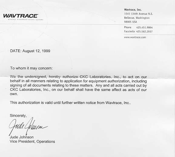
Federal Communications Commission 7435 Oakland Mills Road Columbia, MD 21046 Gentlemen: This letter is to comply with Section 0.457(d)(2)(i) pertaining to confidential material. Wavtrace, Inc. would like the following documents regarding this submission for FCC ID: OPU-PTM1000-28 to be kept confidential. 1. 7020-0012-00, Peregrine Tracelink Specification, 16 pages 2. 7020-0031-00, MMW Transceivers Specification, 4 pages 3. 7050-0003-00, PEREGRINE SYSTEM DESCRIPTION, 55 pages 4. 6585-0004-00RB, Remote Dish Antenna, 28/31GHZ, drawing, 1 page 5. 2020-0114-00RA, Horn Assembly, 30 DEG, Vertical Polarization, HG, 28/31GHZ drawing, 1 page 6. 7020-0000-00, Hub and Subscriber Antenna Specification, 7 pages 7. 2260-0053-03, TRX IFP-S schematic (common to 28GHz, 31GHz, & 38GHz), 12 pages 8. 2260-0054-02, TRX-S Controller schematic (common to 28GHz, 31GHz, & 38GHz), 15 pages 9. 2260-0074-01, TRX, PWR SUPP, DC-DC CONVTR, schematic (common to 28GHz, 31GHz, & 38GHz), 2 pages 10. 2260-0066-01, 1ST LOCAL OSCILLATOR,28GHZ, schematic, 3 pages 11. 2260-0065-01, FE, CONTROLLER,28GHZ, schematic, 7 pages 12. 7220-0012-00, IEEE C95.1-1991 Explosure Analysis, 4 pages The above material contains trade secrets or technical data, which would customarily be guarded from competitors. We do not want these documents to be accessible to the general public. Sincerely, Joyce Walker CKC Laboratories, Inc. 5473A Clouds Rest Mariposa, CA 95338 1-800-500-4362 [email protected]
Cover Letter(s)
Federal Communications Commission 7435 Oakland Mills Road Columbia, MD 21046 Gentlemen: This letter is to confirm that Wavtrace, Inc. would like the following attached documents regarding this submission for FCC ID: {number}to be kept confidential. {see Attachment 1 of documents to be kept confidential} We do not want these documents to be accessible to the general public. Sincerely, {Signed by Company Counsel or Company Officer} Attachment 1: LIST OF DOCUMENTS FOR CONFIDENTIALITY ATTACHMENT 1 LIST OF DOCUMENTS FOR CONFIDENTIALITY 1. 7020-0012-00, Peregrine Tracelink Specification, 16 pages 2. 7020-0031-00, MMW Transceivers Specification, 4 pages 3. 7050-0003-00, PEREGRINE SYSTEM DESCRIPTION, 55 pages 4. 6585-0003-00RB, Remote Dish Antenna, 38GHZ, drawing, 1 page 5. 6585-0004-00RB, Remote Dish Antenna, 28/31GHZ, drawing, 1 page 6. 2020-0004-04RA, Horn Assembly, 30 DEG, Vertical Polarization, HG, 38GHZ drawing, 1 page 7. 2020-0114-00RA, Horn Assembly, 30 DEG, Vertical Polarization, HG, 28/31GHZ drawing, 1 page 8. 7020-0000-00, Hub and Subscriber Antenna Specification, 7 pages 9. 2260-0053-03, TRX IFP-S schematic (common to 28GHz, 31GHz, & 38GHz), 12 pages 10. 2260-0054-02, TRX-S Controller schematic (common to 28GHz, 31GHz, & 38GHz), 15 pages 11. 2260-0074-01, TRX, PWR SUPP, DC-DC CONVTR, schematic (common to 28GHz, 31GHz, & 38GHz), 2 pages 12. 2260-0066-01, 1ST LOCAL OSCILLATOR,28GHZ, schematic, 3 pages 13. 2260-0065-01, FE, CONTROLLER,28GHZ, schematic, 7 pages 14. 2260-0073-01, 1ST LOCAL OSCILLATOR,31GHZ, schematic, 3 pages 15. 2260-0072-01, FE, CONTROLLER, 31GHZ, schematic, 7 pages 16. 2260-0068-01, FE, CONTROLLER, 38GHZ, schematic, 7 pages 17. 2260-0069-01, 1ST LOCAL OSCILLATOR,38GHZ, schematic, 3 pages 18. 7150-0018-00, PTM-100 Transmitter/Receiver Assembly (TRA), 14 pages
ID Label/Location Info
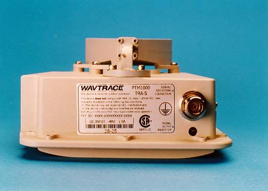
6705-0051-00R02 Nameplate, PTM 1000 TRA-S, APPROVED Dimensions: Width: 3.0" Height: 1.5" Font: Helvetica Regular PTM 1000 TRA-S SERIAL NUMBER DC INPUT -48 VDC 1.0 AMP This device complies with part 15, class A of the FCC rules. Operation is subject to the following two conditions: (1) This device may not cause harmful interference, and (2) This device must accept any interference received including interference that may cause undesired operation. FCC ID: OPU-PTM1000-28 Made in USA SIGNAL/ GROUNDING CONNECTION SIGNAL ACTIVE INDICATOR
ID Label/Location Info
6705-0051-01RA Nameplate, PTM 1000 TRA-28, APPROVED Dimensions: Width: 3.0" Height: 1.5" Font: Helvetica Regular PTM 1000 TRA-28 SERIAL NUMBER DC INPUT -48 VDC 1.0 AMP This device complies with part 15, class A of the FCC rules. Operation is subject to the following two conditions: (1) This device may not cause harmful interference, and (2) This device must accept any interference received including interference that may cause undesired operation. FCC ID: OPU-PTM1000-28 CSA File: 200424 Made in USA SIGNAL CONNECTION SIGNAL ACTIVE INDICATOR
Operational Description
January 10, 2000 Frank Coperich Federal Communications Commission OET Lab. 7435 Oakland Mills Rd. Columbia, MD 21046 RE: FCC ID#: OPU-PTM1000-28 Conf. #: EA95429 Dear Frank Coperich: The list below will explain the correlation between the Description block of the Exhibits that we have submitted and what document is actually being described: In section 5 - Schematics: 1. Power Supply - 2260-0074-01, TRX, PWR SUPP, DC-DC CONVTR, schematic (common to 28GHz, 31GHz, & 38GHz), 2 pages 2. IFP - 2260-0053-03, TRX IFP-S schematic (common to 28GHz, 31GHz, & 38GHz), 12 pages 3. Controller - 2260-0054-02, TRX-S Controller schematic (common to 28GHz, 31GHz, & 38GHz), 15 pages 4. controller - 2260-0065-01, FE, CONTROLLER, 28GHZ, schematic, 7 pages 5. oscillator - 2260-0066-01, 1 st Local Oscillator, 28 GHz, schematic, 3 pages In section 12 – Operational Description 6. Specifications - 7020-0012-00, Peregrine Tracelink Specification, 16 pages 7. Transceiver Specifications – This document should have been deleted. 8. System Description - 7050-0003-00, PEREGRINE SYSTEM DESCRIPTION, 55 pages 9. Antenna Specifications – 7020-0000-00, Hub and Subscriber Antenna Specifications, 7 pages. 10. Remote Dish Antenna - 6585-0004-00RB, Remote Dish Antenna, 28/31GHZ, drawing, 1 page – 2 –April 30, 2001 11. Horn Assembly - 2020-0114-00RA, Horn Assembly, 30 DEG, Vertical Polarization, HG, 28/31GHZ drawing, 1 page 12. System Operational Overview – 7150-0018-00, PTM-1000 Transmitter/Receiver Assembly (TRA), 14 pages Sincerely, Dean Busch Compliance Engineer Wavtrace, Inc.
Parts List/Tune Up Info
PTM 1000 Operations and Maintenance Manual Wavtrace, Inc. 1545 134th Avenue N.E. Belle…
Text truncated - open the document above for the full version.
Contact Information
Applicant
Dean Busch(Reliability, Serviceability Engineer)
Technical Contact
Wavtrace, Inc.Dean Busch
[email protected]425-468-2241
1545 134th Ave. NE · Bellevue, Washington · United States
Non-Technical Contact
CKC Laboratories, Inc.Dean Busch
[email protected]425 468-2241
Test Firm
CKC Laboratories, Inc.Steve Behm
Technical Specifications
| # | Rule Parts | Frequency Range | Power Output | Emission | Tolerance |
|---|---|---|---|---|---|
| 1 | 101 | 27.51 GHz - 28.34 GHz | 39.00 mW | 8M10DXW | 1.0000000000 ppm |
Other Applications from Wavtrace, Inc.
![PTM1000 (TRA 1000S, FE, 1.4, 31GHz [S1]) - FCC ID OPU-PTM1000-31 - Wavtrace, Inc.](/_next/image?url=%2Fapi%2Ffiles%2Fs2%2Fproducts%2FOPU-PTM1000-31%2Fff017d08f6738c87_0.jpg&w=3840&q=75)
OPU-PTM1000-31
Jan 30, 2000PTM1000 (TRA 1000S, FE, 1.4, 31GHz [S1])
Equipment Class
TNB - Licensed Non-Broadcast Station Transmitter![PTM1000 (TRX 1000S, FR, 9.4, 38GHz [S1]) - FCC ID OPU-PTM1000-38 - Wavtrace, Inc.](/_next/image?url=%2Fapi%2Ffiles%2Fs2%2Fproducts%2FOPU-PTM1000-38%2F044974383e3691e1_0.jpg&w=3840&q=75)
OPU-PTM1000-38
Jan 30, 2000PTM1000 (TRX 1000S, FR, 9.4, 38GHz [S1])
Equipment Class
TNB - Licensed Non-Broadcast Station Transmitter