OPWNEONLAMP201207Neon Lamp
Liting Universal (Zhejiang) Co., Ltd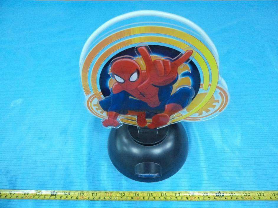
Click to zoom
Application Details
- Equipment Class
- 8CC - Part 18 Consumer Device
- Date of Grant
- Sep 26, 2012
- Application Purpose
- Original Equipment
- Date of Application
- Sep 26, 2012
- Equipment Note
- Neon Lamp
- Frequency Range
- 0.02000000 - 0.02400000
- Country
- China
Documents & Files
Document Text
Text extracted from the exhibit documents filed with the FCC. Open a document above to read the original.
Users Manual
Neon Light Operating and Safety Instructions - FOR HOUSEHOLD USE ONLY - IMPORTANT SAFEGUARDS Definitions Whenever used, the following identify safety and property damage messages and designate a level of hazard seriousness. - This is the safety alert symbol. It alerts you to potential personal injury hazards. Obey all safety messages that follow this symbol to avoid possible injury or death. DANGER – Indicates a hazardous situation, which, if not avoided, will result in death or serious injury. Usage of this signal word is limited to the most extreme situations. WARNING – Indicates a hazardous situation, which, if not avoided, could result in death or serious injury. CAUTION – Indicates a hazardous situation, which, if not avoided, may result in minor/moderate injury. NOTICE – Addresses practices not related to personal injury, such as product and/or property damage. READ ALL INSTRUCTIONS BEFORE USE. 2 NOTE: This product is packed with an Underwriter’s Laboratories (UL) listed power adapter. The combined neon light and power adapter have not been evaluated for UL Listing. WARNING-- To reduce the risk of fire, electric shock, or serious personal injury: • Keep this product out of the reach of small children and pets. This product is not a toy! Extra caution and close supervision are necessary when using this product near children or the physically challenged. • Always ensure the product is unplugged before relocating, cleaning, or storing it. Always unplug the product when it is not in use. • Do not leave the product unattended while it is in use, especially when children are present. • Do not plug/unplug the product with a wet hand. • Keep the power cord and product away from sources of heat. • To disconnect the product from an electrical outlet, turn the power switch to the off position and then pull on the adapter; do not pull on the power cord. • Do not immerse in water or other liquids. • Do not operate this product if it has a damaged power cord or adapter, if it malfunctions, or if it has been dropped in water or damaged in any way. Do not attempt to examine or repair this product. Permanently discontinue use if the neon tube is cracked or damaged. CAUTION-- To reduce the risk of personal injury: • This product is intended solely for non-commercial, non-industrial, indoor use as a decoration only; do not use outdoors or for any other purpose. • Do not cover or use any attachments with the product. • Do not allow the power cord to hang (e.g., over the edge of a table or counter) where it may be tripped over or pulled. NOTICE-- To reduce the risk of product and/or property damage: • Handle the product with care. • Do not subject the product to impacts, extreme temperatures, or long periods of direct sunlight. • Always place the product on a flat, level, stable surface. 3 IMPORTANT INFORMATION REQUIRED BY THE FCC This equipment has been tested and found to comply with the limits for consumer ISM equipment, pursuant to Part 18 of the FCC Rules. These limits are designed to provide reasonable protection against harmful interference in a residential installation. This equipment generates, uses, and can radiate radio frequency energy and, if not installed and used in accordance with the instructions, may cause harmful interference to radio communications. However, there is no guarantee that interference will not occur in a particular installation. If this equipment does cause harmful interference to radio or television reception, which can be determined by turning the equipment off and on, the user is encouraged to try to correct the interference by one or more of the following measures: ― Reorient or relocate the receiving antenna. ― Increase the separation between the equipment and receiver. ― Connect the equipment into an outlet on a circuit different from that to which the receiver is connected. ― Consult the dealer or an experienced radio TV technician for help. NOTE: This product may cause interference to radio equipment and should not be installed near maritime safety communications equipment or other critical navigation or communication equipment operating between 0.45-30 MHz. SAVE THESE INSTRUCTIONS FOR FUTURE REFERENCE NL-1201 NL-1202 NL-1203 NL-1204 NL-1205 NL-1206 NL-1207 NL-1208 4 To Use WARNING: Do not plug in until properly assembled. 1. Insert the power adapter into the jack in the base and then plug the adapter into a standard electrical outlet. 2. For LED and neon effect, push the switch to the “II” position, or for LED only effect, push the power switch to the “I” position. 3. To turn off, push the switch to the “O” position and then unplug from the outlet. WARNING: Always unplug the product from the electrical outlet when not in use or if it will be left unattended. Care and Maintenance WARNING: Always unplug the product from the electrical outlet before cleaning or storing it. • If necessary, clean the product with a soft, dry cloth. NOTICE: Do not use liquids or harsh or abrasive cleaners/pads. • When not in use, wind the cord and store the product in a cool, dry location away from direct sunlight. • If neon tube is broken, wear gloves to clean up. WARNING: Permanently discontinue use if the neon tube is cracked or damaged. Do not attempt to examine or repair this product. Electrical Specifications Input 100V-120 V, 60 Hz, 0.2 A Output 12 V, 0.3 A Item #A14D1603/1604/1605/1606 WIC #170715/170716/170717/170718 ©2012 All Rights Reserved Distributed By: Walgreen Co. 200 Wilmot Rd. Deerfield, IL 60015
Cover Letter(s)
1002 (816x1123x256 jpeg)
External Photos
EXHIBIT B - EUT EXTERNAL PHOTOGRAPHS Model: NL-1201 EUT – Front View EUT – Rear View EUT – Bottom View Model: NL-1202 EUT – Front View EUT – Rear View EUT – Bottom View Model: NL-1203 EUT – Front View EUT – Rear View EUT – Bottom View Model: NL-1204 EUT – Front View EUT – Rear View EUT – Bottom View Model: NL-1205 EUT – Front View EUT – Rear View EUT – Bottom View Model: NL-1206 EUT – Front View EUT – Rear View EUT – Bottom View Model: NL-1207 EUT – Front View EUT – Rear View EUT – Bottom View Model: NL-1208 EUT – Front View EUT – Rear View EUT – Bottom View EUT – Adapter View EUT – Adapter Label View
ID Label/Location Info
EXHIBIT A - FCC ID LABEL AND LOCATION FCC ID Label FCC ID Label Location
Internal Photos
EXHIBIT C - EUT INTERNAL PHOTOGRAPHS Model: NL-1201 EUT – Cover off View EUT – Main Board Top View EUT – Main Board Bottom View EUT – RK12-18-2/RK12-18-3 Board Top View EUT – RK12-18-2/RK12-18-3 Board Bottom View Model: NL-1202 EUT – Cover off View EUT – Main Board Top View EUT – Main Board Bottom View EUT – RK12-18-2/RK12-18-3 Board Top View EUT – RK12-18-2/RK12-18-3 Board Bottom View Model: NL-1203 EUT – Cover off View EUT – Main Board Top View EUT – Main Board Bottom View EUT – RK12-18-2/RK12-18-3 Board Top View EUT – RK12-18-2/RK12-18-3 Board Bottom View Model: NL-1204 EUT – Cover off View EUT – Main Board Top View EUT – Main Board Bottom View EUT – RK12-18-2/RK12-18-3 Board Top View EUT – RK12-18-2/RK12-18-3 Board Bottom View Model: NL-1205 EUT – Cover off View EUT – Main Board Top View EUT – Main Board Bottom View EUT – RK12-18-4 Board Top View EUT – RK12-18-4 Board Bottom View Model: NL-1206 EUT – Cover off View EUT – Main Board Top View EUT – Main Board Bottom View EUT – RK12-18-4 Board Top View EUT – RK12-18-4 Board Bottom View Model: NL-1207 EUT – Cover off View EUT – Main Board Top View EUT – Main Board Bottom View EUT – RK12-18-4 Board Top View EUT – RK12-18-4 Board Bottom View Model: NL-1208 EUT – Cover off View EUT – Main Board Top View EUT – Main Board Bottom View EUT – RK12-18-2 Board Top View EUT – RK12-18-2 Board Bottom View
Schematics
1 2 3 4 56 ABCD 6 5 4 3 2 1 D CBA Title Number Revision Size B Date: 18-Jul-2012 Sheet of File: C:\Do cu ment s an d Sett in gs \Ad mini st rato r\ 桌面 \NH D.dd b Drawn By: C2100V 47N L1 LED Q1C1008Q2C1008 510 Ω R1 K3 K2 B LED LEDLED LEDD?LED LED LED LED K1 DC12V 300MA +- LAMP C3 3KV 10PF/15PF 510 Ω 510 Ω 1K Ω 1K Ω 1K Ω LED 510 Ω LED LED 510 Ω LED Circuit diagram fo r NL-1201,NL-1202,NL-1203,NL-1204 1K Ω 1 2 3 4 56 ABCD 6 5 4 3 2 1 D CBA Title Number Revision Size B Date: 18-Jul-2012 Sheet of File: C:\Do cu ment s an d Sett in gs \Ad mini st rato r\ 桌面 \ 米老鼠,公主单 .dd b Drawn By: C2100V 47N L1 LED Q1C1008Q2C1008 1K Ω R1 K3 K2 B LED LED K1 DC12V 300MA +- LAMP C3 3KV 10PF/15PF 1K Ω 1K Ω LED 1K Ω LED 1K Ω Circuit diagram for NL-1205,NL-1206,NL-1207 1K Ω 1 2 3 4 56 ABCD 6 5 4 3 2 1 D CBA Title Number Revision Size B Date: 18-Jul-2012 Sheet of File: C:\Do cu ment s an d Sett in gs \Ad mini st rato r\ 桌面 \ 公主双霓虹灯 .dd b Drawn By: C2100V 47N L1 LED Q1C1008Q2C1008 510 Ω R1 K3 K2 B LED LED K1 DC12V 300MA +- LAMP C3 3KV 10PF/15PF 510 Ω 510 Ω LED 510 Ω LED 510 Ω Circuit diagram for NL-1208 1K Ω LED LED LED LED LED
Test Report
Note: This test report is prepared for the customer shown above and for the device described herein. It may not be duplicated or used in part without prior written consent from Bay Area Compliance Laboratories Corp. This report must not be used by the customer to claim product certification, approval, or endorsement by NVLAP*, or any agency of the Federal Government. * This report may contain data that are not covered by the NVLAP accreditation and shall be marked with an asterisk “★” FCC PART 18 TEST REPORT For Liting Universal (Zhejiang) Co., Ltd. Jinsha Village, Quantang Industry Zone, Pinghu City, Zhejiang 314204, China FCC ID: OPWNEONLAMP201207 Report Type: Original Report Product Type: Neon Lamp Test Engineer: Andrew Shu Report Number: RSZ120719806-00 Report Date: 2012-09-17 Reviewed By: Dick Zhang EMC Leader Test Laboratory: Bay Area Compliance Laboratories Corp. (Shenzhen) 6/F, the 3rd Phase of WanLi Industrial Building ShiHua Road, FuTian Free Trade Zone Shenzhen, Guangdong, China Tel: +86-755-33320018 Fax: +86-755-33320008 www.baclcorp.com.cn Bay Area Compliance Laboratories Corp. (Shenzhen) Report No.: RSZ120719806-00 FCC Part 18 Page 2 of 38 TABLE OF CONTENTS GENERAL INFORMATION ...................................................................................................................................... 3 PRODUCT DESCRIPTION FOR EQUIPMENT UNDER TEST (EUT) .................................................................................... 3 OBJECTIVE................................................................................................................................................................... 3 RELATED SUBMITTAL(S)/GRANT(S) ............................................................................................................................ 3 TEST METHODOLOGY.................................................................................................................................................. 3 TEST FACILITY............................................................................................................................................................ 4 SYSTEM TEST CONFIGURATION ......................................................................................................................... 5 JUSTIFICATION............................................................................................................................................................. 5 EUT EXERCISE SOFTWARE.......................................................................................................................................... 5 SPECIAL ACCESSORIES................................................................................................................................................ 5 EQUIPMENT MODIFICATIONS....................................................................................................................................... 5 EXTERNAL I/O CABLE................................................................................................................................................. 5 BLOCK DIAGRAM OF TEST SETUP................................................................................................................................5 FCC §18.307 - AC LINE CONDUCTED EMISSIONS ............................................................................................. 6 MEASUREMENT UNCERTAINTY................................................................................................................................... 6 EUT SETUP................................................................................................................................................................. 6 EMI TEST RECEIVER SETUP........................................................................................................................................ 6 TEST EQUIPMENT LIST AND DETAILS.......................................................................................................................... 7 TEST PROCEDURE........................................................................................................................................................ 7 TEST RESULTS SUMMARY........................................................................................................................................... 7 TEST DATA.................................................................................................................................................................. 7 FCC §18.305 – FIELD STRENGTH ......................................................................................................................... 24 MEASUREMENT UNCERTAINTY................................................................................................................................. 24 EUT SETUP............................................................................................................................................................... 24 EMI TEST RECEIVER SETUP...................................................................................................................................... 24 TEST EQUIPMENT LIST AND DETAILS........................................................................................................................ 25 TEST PROCEDURE...................................................................................................................................................... 25 CORRECTED AMPLITUDE CALCULATION................................................................................................................... 25 TEST DATA................................................................................................................................................................ 25 PRODUCT SIMILARITY DECLARATION LETTER......................................................................................... 38 B…
Text truncated - open the document above for the full version.
Test Setup Photos
EXHIBIT D - TEST SETUP PHOTOGRAPHS AC Line Conduction Emissions – Front View (Model: NL-1201) AC Line Conduction Emissions – Side View (Model: NL-1201) AC Line Conduction Emissions – Front View (Model: NL-1202) AC Line Conduction Emissions – Side View (Model: NL-1202) AC Line Conduction Emissions – Front View (Model: NL-1203) AC Line Conduction Emissions – Side View (Model: NL-1203) AC Line Conduction Emissions – Front View (Model: NL-1204) AC Line Conduction Emissions – Side View (Model: NL-1204) AC Line Conduction Emissions – Front View (Model: NL-1205) AC Line Conduction Emissions – Side View (Model: NL-1205) AC Line Conduction Emissions – Front View (Model: NL-1206) AC Line Conduction Emissions – Side View (Model: NL-1206) AC Line Conduction Emissions – Front View (Model: NL-1207) AC Line Conduction Emissions – Side View (Model: NL-1207) AC Line Conduction Emissions – Front View (Model: NL-1208) AC Line Conduction Emissions – Side View (Model: NL-1208) Radiated Emissions View (Model: NL-1201) Radiated Emissions View (Model: NL-1202) Radiated Emissions View (Model: NL-1203) Radiated Emissions View (Model: NL-1204) Radiated Emissions View (Model: NL-1205) Radiated Emissions View (Model: NL-1206) Radiated Emissions View (Model: NL-1207) Radiated Emissions View (Model: NL-1208)
Contact Information
Applicant
Chen Micky
Test Firm
Bay Area Compliance Laboratory Corp. (Shenzhen)John Chan
Technical Specifications
| # | Rule Parts | Frequency Range | Power Output |
|---|---|---|---|
| 1 | 18 | 0.02 MHz - 0.024 MHz | - |