OSAMR1145RADIOTELEPHONE MR1145
Motorola Solutions Germany GmbH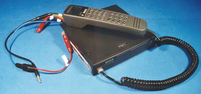
Click to zoom
Application Details
- Equipment Class
- TNB - Licensed Non-Broadcast Station Transmitter
- Date of Grant
- Feb 07, 2000
- Application Purpose
- Original Equipment
- Date of Application
- Nov 07, 1999
- Equipment Note
- RADIOTELEPHONE MR1145
- Frequency Range
- 440.00000000 - 470.00000000
- Country
- United States
Documents & Files
Document Text
Text extracted from the exhibit documents filed with the FCC. Open a document above to read the original.
Users Manual
KraftfahrzeugsprechfunkgerätMobile RadiotelephoneRadiotéléphone pour véhiculeMR 11 S-C · MR 11 SD-Rmit / with / avecML 11 · HBT 11 · HA 11 · BTM-XBBedienungsanleitung · Operating Manual · Mode d’emploi 923991 19 . 10 . 1999 10 : 27 Uhr Seite 1 2 923991 19 . 10 . 1999 10 : 27 Uhr Seite 2 3 Kurzbedienungsanleitung / Operating instructions in brief /Mode d’emploi sommaireMR 11 SD-R mit / with / avec HBT 11 923991 19 . 10 . 1999 10 : 27 Uhr Seite 3 BedienelementePos. Benennung Tastensymbol, Standardfunktion Displaysymbol 1 Display 2* Ruftaste 1 I Festruf 3* Lautsprechertaste o Lautsprecher ein/aus, mithören 4* Ruftaste 2 Displayruf 5* Ein/Aus-Taste Gerät ein/aus Kurz: einLang: aus 6* Sendetaste : : : Sprechtaste 7 Cursortaste Verschieben der Eingabestelle im Display Kurz: rechtsLang: links 8 Menütaste Aufruf eines Menüs Kurz: nächster MenüpunktLang: Menü 1 9 Plus-Taste Eingabestelle aufwärts 10 Minus-Taste Eingabestelle abwärts 18 Sende-/ Empfangssymbol Nicht in Verwendung 19 Kanal belegt 20 Nicht in Verwendung 21 Senden 22 Lautsprechersymbol Lautsprecher ein 23 Rufumleitungs- Rufumleitung geschaltet symbol24 Mit 23 zusammen 25 Kennungssymbol Nummer des Rufenden empfangen 26 Mit 25 zusammen 4 D 923991 19 . 10 . 1999 10 : 27 Uhr Seite 4 27 Anzeige- Überlaufsymbol Rechts weitere Zeichen 28 Nicht in Verwendung 29 Links weitere Zeichen 30 Rechts und links weitere Zeichen 31 Batteriesymbol Bei MR-Geräten ohne Funktion 32 Balkenanzeige Bei MR-Geräten ohne Funktion 33 Leuchtdiode rot Senden 34 Leuchtdiode gelb Funkkanal belegt 35 Leuchtdiode grün Lautsprecher ein Dauer: durch TastendruckBlinkt: durch Anruf 36 Lautsprecher 37 Mikrofon 38 10-polige FCC-Buchse Für Bedienteilanschluß 40 +, –, externe Hupe oder Notrufanschluß 41 Datenbuchse * Pos. 2–6 können auf Kundenwunsch mit anderen Funktionen belegt werden. Bitte überzeugen Sie sich in dem Programmierausdruck, den IhrFunkhändler der Bedienungsanleitung beigelegt hat, von der aktuellenFunktion dieser Tasten. 5 D 923991 19 . 10 . 1999 10 : 27 Uhr Seite 5 6 923991 19 . 10 . 1999 10 : 27 Uhr Seite 6 Kurzbedienungsanleitung / Operating instructions in brief /Mode d’emploi sommaireMR 11 S-C mit / with / avec ML 11 oder / or / ou HM 11-1/3 7 923991 19 . 10 . 1999 10 : 27 Uhr Seite 7 BedienelementePos. Benennung Tastensymbol, Standardfunktion Displaysymbol 1 Display 2* Ruftaste 1 Festruf 3* Lautsprechertaste o Lautsprecher ein/aus, mithören 4* Ruftaste 2 Displayruf 5* Ein/Aus-Taste Gerät ein/aus Kurz: einLang: aus 6* Sendetaste : : : Sprechtaste 7 Cursortaste Verschieben der Eingabestelle im Display Kurz: rechtsLang: links 8 Menütaste Aufruf eines Menüs Kurz: nächster MenüpunktLang: Menü 1 9 Plus-Taste Eingabestelle aufwärts 10 Minus-Taste Eingabestelle abwärts 11* Dreieckstaste (F1) Programmierbare Taste 18 Sende-/ Empfangssymbol Nicht in Verwendung 19 Kanal belegt 20 Nicht in Verwendung 21 Senden 22 Lautsprechersymbol Lautsprecher ein 23 Rufumleitungs- Rufumleitung geschaltet symbol24 Mit 23 zusammen 25 Kennungssymbol Nummer des Rufenden empfangen 26 Mit 25 zusammen 8 D 923991 19 . 10 . 1999 10 : 27 Uhr Seite 8 27 Anzeige- Überlaufsymbol Rechts weitere Zeichen 28 Nicht in Verwendung 29 Links weitere Zeichen 30 Rechts und links weitere Zeichen 31 Batteriesymbol Bei MR-Geräten ohne Funktion 32 Balkenanzeige Bei MR-Geräten ohne Funktion 33 Leuchtdiode rot Senden 34 Leuchtdiode gelb Funkkanal belegt 35 Leuchtdiode grün Lautsprecher ein Dauer: durch TastendruckBlinkt: durch Anruf 36 Lautsprecher 37 Mikrofon 38 10-polige FCC-Buchse Für Bedienteilanschluß 40 +, –, externe Hupe oder Notrufanschluß * Pos. 2–6 und 11 können auf Kundenwunsch mit anderen Funktionen belegt werden. Bitte überzeugen Sie sich in dem Programmierausdruck,den Ihr Funkhändler der Bedienungsanleitung beigelegt hat, von der ak-tuellen Funktion dieser Tasten. 9 D 923991 19 . 10 . 1999 10 : 27 Uhr Seite 9 10 923991 19 . 10 . 1999 10 : 27 Uhr Seite 10 11 Kurzbedienungsanleitung / Operating instructions in brief /Mode d’emploi sommaire MR 11 SD-R mit / with / avec BTM-XB und / and / et ML 11 oder / or / ou HM 11-1/3 923991 19 . 10 . 1999 10 : 27 Uhr Seite 11 BedienelementePos. Benennung Tastensymbol, Standardfunktion Displaysymbol 1 Display 2* Ruftaste 1 I Festruf 3* Lautsprechertaste Lautsprecher ein/aus, mithören 4* Ruftaste 2 Displayruf 5* Ein/Aus-Taste Gerät ein/aus Kurz: einLang: aus 6* Sendetaste : : : Sprechtaste 7 Cursortaste Verschieben der Eingabestelle im Display Kurz: rechtsLang: links 8 Menütaste Aufruf eines Menüs Kurz: nächster MenüpunktLang: Menü 1 9 Plus-Taste Eingabestelle aufwärts 10 Minus-Taste Eingabestelle abwärts 11* Funktionstaste 1 Programmierbare Taste 12* Funktionstaste 2 Programmierbare Taste 13* Funktionstaste 3 Programmierbare Taste 14* Funktionstaste 4 Programmierbare Taste 15 Ziffernblock 0–9 Zifferneingabe 16* Sterntaste Displayinhalt löschen Kurz: markierte StelleLang: alle Eingabestellen 17* Rautentaste Eingabe des Gruppen- ruftones „G“ 19 Empfangssymbol Kanal belegt 20 Nicht in Verwendung 21 Sendesymbol Senden 22 Lautsprechersymbol Lautsprecher ein 23 Rufumleitungs- Rufumleitung geschaltet symbol 12 D 923991 19 . 10 . 1999 10 : 27 Uhr Seite 12 25 Kennungssymbol Nummer des Rufenden empfangen 26 Mit 25 zusammen 27 Anzeige- Überlaufsymbol Rechts weitere Zeichen 28 Nicht in Verwendung 29 Links weitere Zeichen 30 Rechts und links weitere Zeichen 31 Batteriesymbol Bei MR-Geräten ohne Funktion 32 Balkenanzeige Bei MR-Geräten ohne Funktion 36 Lautsprecher 37 Mikrofon 38 10-polige FCC-Buchse Für Bedienteilanschluß 40 +, –, externe Hupe oder Notrufanschluß 41 Datenbuchse 44 Funkgeräteanschluß Verbindung zum Funkgerät 45 10-polige FCC-Buchse Für den Anschluß derBesprechungs-EinrichtungenML 11, HM 11-1 und HM 11-3 * Pos. 2–6, 11–14 und 16, 17 können auf Kundenwunsch mit anderen Funk- tionen belegt werden. Bitte überzeugen Sie sich in dem Programmieraus-druck, den Ihr Funkhändler der Bedienungsanleitung beigelegt hat, vonder aktuellen Funktion dieser Tasten. 13 D 923991 19 …
Text truncated - open the document above for the full version.
Users Manual
Motorola GmbH • Geschäftsbereich Funksysteme >> I Service Manual Radiotelephones MR 11 Edition 2 Product survey 1 Technical description, external connections 2 Circuit diagrams 3 Spare parts 4 Assembly and conversion instructions 5 Service accessories 6 Programming with WinIPP 7 © All rights reserved by Motorola GmbH • Geschäftsbereich Funksysteme, also for patent and trade mark applications. Rights of disposal, e.g. copyright and right of transfer to third parties, are likewise held by us. Motorola GmbH • Geschäftsbereich Funksysteme .. - 1 <<>> I Technical Description MR 11 and Description of the External Connections Table of Contents 1General Information2 - 2 2Technical Data2 - 2 3Circuit Description2 - 3 3.1 Receiver2 - 3 3.2 Transmitter2 - 4 3.3 Antenna Filter with Antenna Switch2 - 4 3.4 Frequency Conditioning2 - 5 3.5 Analog Signal Processing2 - 6 3.6 Unit Control2 - 6 3.7 Signalling Module MDSR 1342 - 7 4Function of the External Connections2 - 8 4.1 4-pin Rear Connection2 - 8 4.2 10-pin FCC Plug2 - 9 4.3 25-pin Socket (Data Interface MR 11..R)2 - 9 2 - 1 MR 11 Motorola GmbH • Geschäftsbereich Funksysteme .. - 1 <<>> I 1General Information The MR 11 radio family has been designed on a common technical basis. This means: largely the same components, the same circuit technology, the same software and the same user interface. The radios are designed both for private mobile radio and trunking systems. The MR 11 is the mobile radio in this new radio family. There are two models: the C radios with an integrated control unit for voice transmission and the R radios (without control unit) with connection facility for external data equipment and control units for voice transmission. 2Technical Data MR 11.. S-CMR 11.. SD-R MR 11.. T-CMR 11.. TD-R Brief descriptionWith integrated keyboard and LCDWith 25-pin data connection External connection10-pin FCC socket,10-pin FCC socket, loudspeaker and follower contactloudspeaker, follower contact and 25-pin Sub-D socket Frequency range MR 1116146 - 174 MHz146 - 174 MHz MR 1142 Receiver400 - 440 MHz400 - 440 MHz Transmitter Part A (1 - 6 W)400 - 420 MHz400 - 420 MHz Part B (1 - 6 W)420 - 440 MHz420 - 440 MHz Part C (10 - 25 W)400 - 425 MHz400 - 425 MHz Part D (10 - 25 W)425 - 440 MHz425 - 440 MHz MR 1145440 - 470 MHz440 - 470 MHz Channel spacing20 / 25 kHz, 12.5 kHz20 / 25 kHz, 12.5 kHz Number of channels999999 Transmitter and receiverTransmitter and receiver freely programmablefreely programmable AF output power4 W on 4 4 W on 4 SignallingAnalog / digitalAnalog / digital Antenna connectionBNCBNC Dimensions (W x H x D)178 x 35 x 165 mm178 x 35 x 165 mm Weight1,100 g1,100 g Protection classIP 50IP 50 2 - 2 MR 11 Motorola GmbH • Geschäftsbereich Funksysteme .. - 1 <<>> I MR 1116MR 1142 MR 1145 Transmitter power0.1 W fixed0.1 W fixed 1 - 6 W1 - 6 W 6 - 12 W1 - 10 W 12 - 25 W10 - 25 W Channel-dependently programmable Channel-dependently programmable Current consumption Standby< 0.3 A< 0.3 A Receive< 0.5 A< 0.5 A Transmit 6 W< 2.3 A< 3 A 10 W—-< 3.5 A 12 W< 3.5 A—- 25 W< 6.8 A< 7 A 3Circuit Description The circuit description and its component references refers directly to individual components in part which can only be found in the design circuit diagrams. 3.1 Receiver The complete receiver module consists of the VHF/UHF pre-stage (RX), a ring mixer, the IF unit (IF) and a power supply (PS). Pre-stage (RX) The pre-stage is responsible for far-off selectivity, attenuation of the image frequency and the total sensitivity. The circuit consists of two band pass filters and one amplifier in emitter circuit. The pass range is divided into four reception ranges by two varicaps in the first band filter. The analog signal VRXTUNE controls the respective reception range. The second band pass filter could be omitted from the MR radio on account of the good selection of the harmonic filter. Double Balanced Mixer In the double balanced mixer, the reception signal is mixed down to the 1st IF level by the applied oscillator signal. 2 - 3 MR 11 Motorola GmbH • Geschäftsbereich Funksysteme .. - 1 <<>> I IF Module The IF module amplifies the 45 MHz signal from the mixer and provides the necessary channel selection by the available crystal and ceramic filters. It supplies a demodulated AF signal to the following AF-IC and provides the computer with an RSSI (received signal strength indicator) signal. Power Supply (PS) The power supply generates the necessary receiver voltage VRX. VRX is derived from the switched battery voltage BATSWD and stabilised at 8 V. VRX is switched on and off by the control line VTXCTRL. 3.2 Transmitter Four adjustment values for four power stages are stored in the radio for the transmitter output stages in production. One of these values can be assigned to the “High Power” stage switchable by the user, another to the “Low Power” stage with the help of WinIPP in the after-sales service. This can be done uniformly for all channels or separately for each channel. To ensure as constant as possible an output power over the whole frequency range, four times four setting values for 146 MHz, 155 MHz, 165 MHz and 174 MHz are determined in automatic adjustment. The switching times for reception-transmission, transmission-reception mode are less than 30 milliseconds. The power supplies for the transmitter are switched on and the T/R switch switched to transmission mode via the control line VTXCTRL. Transmitter Ouput Amplifier The transmitter is available in three power ranges (1-6 W / 6-12 W / 12-25 W). The stored adjustment values for the transmitter power in the MR radios are: 1-6 W:1 W2 W6 W6 W 6-12 W:6 W6 W12 W12 W 12-25 W:12 W12 W25 W25 W The transmitter power of the MR 11 is keyed up with the aid of a D/A converter in the form of a staircase function in two milliseconds. The setting values are passed to the transmitter via the control line VPWRREF after a linear interpolation. 3.3 Antenna Filter with Antenna Switch The antenna filter connects either the…
Text truncated - open the document above for the full version.
Users Manual
Motorola GmbH • Geschäftsbereich Funksysteme .. - 1 <<>> I Refer to note on page 3 - 1 MR 1142 .. C .. MR 1142 .. R .. MR 1145 .. C .. MR 1145 .. R .. Basic unit Index 5 3 - 16 MR 11 Motorola GmbH • Geschäftsbereich Funksysteme .. - 1 <<>> I Refer to note on page 3 - 1 MR 1142 .. C .. MR 1142 .. R .. MR 1145 .. C .. MR 1145 .. R .. Basic unit Index 5 3 - 17 MR 11 Motorola GmbH • Geschäftsbereich Funksysteme .. - 1 <<>> I Refer to note on page 3 - 1 MR 1142 .. C .. MR 1142 .. R .. MR 1145 .. C .. MR 1145 .. R .. Basic unit Index 5 3 - 18 MR 11 Motorola GmbH • Geschäftsbereich Funksysteme .. - 1 <<>> I Refer to note on page 3 - 1 MR 1142 .. C .. MR 1142 .. R .. MR 1145 .. C .. MR 1145 .. R .. Basic unit Index 5 3 - 19 MR 11 Motorola GmbH • Geschäftsbereich Funksysteme .. - 1 <<>> I Refer to note on page 3 - 1 MR 11 .. C .. Control unit Index 5 3 - 20 MR 11 Motorola GmbH • Geschäftsbereich Funksysteme .. - 1 <<>> I Refer to note on page 3 - 1 MR 11 .. C .. Control unit Index 5 3 - 21 MR 11 Motorola GmbH • Geschäftsbereich Funksysteme .. - 1 <<>> I Refer to note on page 3 - 1 Microphone-Loudspeaker ML 11 8 698 837 611 Index 2 3 - 22 MR 11: ML 11 Motorola GmbH • Geschäftsbereich Funksysteme .. - 1 <<>> I Refer to note on page 3 - 1 HBT 11 Hand control unit Index 2 3 - 23 MR 11: HBT 11 Motorola GmbH • Geschäftsbereich Funksysteme .. - 1 <<>> I Refer to note on page 3 - 1 HBT 11 Hand control unit Index 2 3 - 24 MR 11: HBT 11 Motorola GmbH • Geschäftsbereich Funksysteme .. - 1 <<>> I Refer to note on page 3 - 1 HA 11 Handset 8 698 840 121 Index 2 3 - 25 MR 11: HA 11
Cover Letter(s)
November 8, 1999 Federal Communications Commission Equipment Authorization Branch 7435 Oakland Mills Road Columbia, Maryland 21046 USA Dear Sir/Madam:Our File Ref. 98529930 FCC ID: OSAMR1145 Applicant: Motorola GmbH Equipment: Radiotelephone MR1145 FCC Confirmation no.: EA95919 We have successfully electronically filed all the required documentation for an application for certification in accordance with FCC Part 90 on the above mentioned equipment, November 8, 1999. Enclosed, please find a cheque in the amount of $520.00 US, a copy of FCC Remittance Form 159, a copy of the FCC Form 731 confirmation number and a copy of the list of exhibits. If you require additional administrative information, please do not hesitate to contact me at 1-800-563-6336 (extension 232). If you require additional technical information, please contact Mr. Russell Grant at same (extension 223). Thank you in advance for your assistance in this matter. Sincerely, Ruby Dulmage Administrative Clerk KTL Ottawa Encl.
ID Label/Location Info
Typschild Ident Plate Dimension: mm 1 Field 1Radio Code Field 2Model Code Field 3Approval Number Field 4Model Number Field 5Serial Number Field 6Internal Order Number Field 7Model + Serial Number Field 8Internal Order Number Field 9Company Name Tamperproof Material The label must be made of tamper-evident material, i.e. the label must tear, distort, or otherwise show evidence of having been tampered with when an attempt is made to remove the label from the radio 1 12345 6 78 101 8 MR 1145 SD-R-A-12-25 GM7692742602 Ser.No.XXXXXXXXX Ord.No. XXXXXX Mot orola GmbH Geschäft sberei ch Funksysteme FCC REN: Typ of Jack: FCC ID: BNC Complies with Part XX,FCC Rules Made in Germany OSAMR1145
Schematics
Motorola GmbH • Geschäftsbereich Funksysteme .. - 1 <<>> I Refer to note on page 3 - 1 MR 1142 .. C .. MR 1142 .. R .. MR 1145 .. C .. MR 1145 .. R .. Basic unit Index 5 3 - 11 MR 11 Motorola GmbH • Geschäftsbereich Funksysteme .. - 1 <<>> I Refer to note on page 3 - 1 MR 1142 .. C .. MR 1142 .. R .. MR 1145 .. C .. MR 1145 .. R .. Basic unit Index 5 3 - 12 MR 11 Motorola GmbH • Geschäftsbereich Funksysteme .. - 1 <<>> I Refer to note on page 3 - 1 MR 1142 .. C .. MR 1142 .. R .. MR 1145 .. C .. MR 1145 .. R .. Basic unit Index 5 3 - 13 MR 11 Motorola GmbH • Geschäftsbereich Funksysteme .. - 1 <<>> I Refer to note on page 3 - 1 MR 1142 .. C .. MR 1142 .. R .. MR 1145 .. C .. MR 1145 .. R .. Basic unit Index 5 3 - 14 MR 11 Motorola GmbH • Geschäftsbereich Funksysteme .. - 1 <<>> I Refer to note on page 3 - 1 MR 1142 .. C .. MR 1142 .. R .. MR 1145 .. C .. MR 1145 .. R .. Basic unit Index 5 3 - 15 MR 11 Motorola GmbH • Geschäftsbereich Funksysteme .. - 1 <<>> I Refer to note on page 3 - 1 MR 1142 .. C .. MR 1142 .. R .. MR 1145 .. C .. MR 1145 .. R .. Basic unit Index 5 3 - 16 MR 11 Motorola GmbH • Geschäftsbereich Funksysteme .. - 1 <<>> I Refer to note on page 3 - 1 MR 1142 .. C .. MR 1142 .. R .. MR 1145 .. C .. MR 1145 .. R .. Basic unit Index 5 3 - 17 MR 11 Motorola GmbH • Geschäftsbereich Funksysteme .. - 1 <<>> I Refer to note on page 3 - 1 MR 1142 .. C .. MR 1142 .. R .. MR 1145 .. C .. MR 1145 .. R .. Basic unit Index 5 3 - 18 MR 11 Motorola GmbH • Geschäftsbereich Funksysteme .. - 1 <<>> I Refer to note on page 3 - 1 MR 1142 .. C .. MR 1142 .. R .. MR 1145 .. C .. MR 1145 .. R .. Basic unit Index 5 3 - 19 MR 11
Test Report
Master: ktlPT90PLMT Date: April 19, 1999 KTL Test Report:98529930 Applicant:Motorola GmbH Zitadellenweg 34 D-13599 Berlin Germany Equipment Under Test:Radiotelephone MR1145 (E.U.T.) FCC ID:OSAMR1145 In Accordance With:FCC Part 90, Subpart I Private Land Mobile Transmitter Tested By:KTL Arnhem Postbus 6004 6800 JA Arnhem The Netherlands Authorized By: Ing. Patric Wender, Test Engineer Date:August 1, 1999 Total Number of Pages:50 KTLFCC PART 90, SUBPART I PRIVATE LAND MOBILE TRANSMITTER PROJECT NO.:98529930 EQUIPMENT: MR 1145 FCC ID: OSAMR1145 Page 2 of 39 Table of Contents Section 1. Summary of Test Results General Summary of Test Data Section 2. General Equipment Specification Specifications Description of Modifications for Class II Permissive Change Modifications Made During Testing Theory of Operation System Diagram Section 3. RF Power Output Test Results Measurement Data Power Over Bandwidth Graphs Section 4. Audio Frequency Response Graphs Table Section 5. Audio Low-Pass Filter Response Graphs Table Section 6. Modulation Limiting Graphs Table Section 7. Occupied Bandwidth Test Results Measurement Data Occupied Bandwidth Plots Section 8. Spurious Emissions @ Antenna Terminals Test Results Measurement Data Spurious Emissions Plots KTLFCC PART 90, SUBPART I PRIVATE LAND MOBILE TRANSMITTER PROJECT NO.:98529930 EQUIPMENT: MR 1145 FCC ID: OSAMR1145 Page 3 of 39 Table of Contents, continued Section 9. Field Strength of Spurious Test Results Test Data Test Data - Radiated Emissions Photographs of Test Setup Section 10. Frequency Stability Test Results Measurement Data Frequency Tables Section 11. Transient Frequency Behaviour Test Results Measurement Data Transient Frequency Behaviour Graphs Section 12. Test Equipment List Annex A - Test Methodologies RF Power Output Audio Frequency Response Audio Low-Pass Filter Frequency Response Modulation Limiting Occupied Bandwidth Field Strength of Spurious Radiation Frequency Stability Transient Frequency Behaviour Annex B - Test Diagrams R.F. Power Output Audio Frequency Response Audio Low-Pass Filter Frequency Response Modulation Limiting Occupied Bandwidth Spurious Emissions at Antenna Terminals Filed Strength of Spurious Radiation Frequency Stability Transient Frequency Behaviour KTLFCC PART 90, SUBPART I PRIVATE LAND MOBILE TRANSMITTER PROJECT NO.:98529930 EQUIPMENT: MR 1145 FCC ID: OSAMR1145 Page 4 of 39 Section 1.Summary of Test Results Manufacturer:Motorola GmbH Model No.:MR1145 SD-R-A-12-25 Serial No.:965 9325 General:All measurements are traceable to national standards. These tests were conducted on a sample of the equipment for the purpose of demonstrating compliance with FCC Part 90, Subpart I. New SubmissionProduction Unit Class II Permissive ChangePre-Production Unit TNB Equipment Code THIS TEST REPORT RELATES ONLY TO THE ITEM(S) TESTED. THE FOLLOWING DEVIATIONS FROM, ADDITIONS TO, OR EXCLUSIONS FROM THE TEST SPECIFICATIONS HAVE BEEN MADE. See “ Summary of Test Data”. NVLAP LAB CODE: 100351-0 TESTED BY: _____________________________________ DATE: ___________________ Ing. Patric Wender, Test Engineer KTL Ottawa Inc. authorizes the above named company to reproduce this report provided it is reproduced in its entirety and for use by the company’s employees only. Any use which a third party makes of this report, or any reliance on or decisions to be made based on it, are the responsibility of such third parties. KTL Ottawa Inc. accepts no responsibility for damages, if any, suffered by any third party as a result of decisions made or actions based on this report. This report applies only to the items tested. KTLFCC PART 90, SUBPART I PRIVATE LAND MOBILE TRANSMITTER PROJECT NO.:98529930 EQUIPMENT: MR 1145 FCC ID: OSAMR1145 Page 5 of 39 Summary Of Test Data NAME OF TESTPARA. NO.SPEC.MEAS.RESULT RF Power Output90.205C Audio Frequency ResponseTIA EIA-603.3.2.6C Audio Low-Pass Filter ResponseTIA EIA-603.3.2.6C Modulation LimitingTIA EIA-603.3.2.6C Occupied Bandwidth90.210C Spurious Emissions at Antenna Terminals 90.210C Field Strength of Spurious Emissions 90.210C Frequency Stability90.213C Transient Frequency Behavior90.214C Footnotes For N/A’s: Test conditionsTemperature:22°C Humidity:55% KTLFCC PART 90, SUBPART I PRIVATE LAND MOBILE TRANSMITTER PROJECT NO.:98529930 EQUIPMENT: MR 1145 FCC ID: OSAMR1145 Page 6 of 39 Section 2.General Equipment Specification Transmitter Supply Voltage Input: 13.2 Vdc Frequency Range: 440 – 470 MHz Tunable Bands: 1 Necessary Bandwidth: 11 kHz Type(s) of Modulation: F3E (Voice) F1DF2DD7W (QAM) Other Data Rate(s) Not Applicable Internal/External Data Source: Not Applicable Emission Designator: 11K0F3E, 11K0G3E Output Impedance: 50 Ω RF Power Output (rated): 10 – 25 Watt Duty Cycle: Continuous Channel Spacing(s): 12.5 kHz Operator Selection of Operating Frequency: The user can only select pre-programmed frequencies. Power Output Adjustment Capability: 2 Power levels KTLFCC PART 90, SUBPART I PRIVATE LAND MOBILE TRANSMITTER PROJECT NO.:98529930 EQUIPMENT: MR 1145 FCC ID: OSAMR1145 Page 7 of 39 Receiver Frequency Range: 440 – 470 MHz Tunable Bands: 1 Local Oscillator: 395 – 425 MHz 1 st IF: 45 MHz 2 nd IF: 455 kHz Operator Selection of Operating Frequency: The user can only select pre-programmed frequencies. KTLFCC PART 90, SUBPART I PRIVATE LAND MOBILE TRANSMITTER PROJECT NO.:98529930 EQUIPMENT: MR 1145 FCC ID: OSAMR1145 Page 8 of 39 Section 3.RF Power Output NAME OF TEST: RF Power OutputPARA. NO.: 2.985 TESTED BY: ing. P.H.J. WenderDATE: 01 August 1999 Test Results:Complies Measurement Data: Frequency (MHz) Measured Power (dBm) Rated Power (dBm) Measured/Rated (dB) 455.02543.844-0.2 455.02540.9400.9 KTLFCC PART 90, SUBPART I PRIVATE LAND MOBILE TRANSMITTER PROJECT NO.:98529930 EQUIPMENT: MR 1145 FCC ID: OSAMR1145 Page 9 of 39 Section 4.Audio Frequency Response NAME OF TEST: Audio Frequency ResponsePARA. NO.: 2.987(a) TESTED BY: ing. P.H.J. WenderDATE: 01 August 1999 -18 -16 -14 -12 -10 -8 -6 -4 -2 0 2 4 6 8 10 12 14 …
Text truncated - open the document above for the full version.
Contact Information
Applicant
Chuck Powers(Director, Engineering and Technology Policy)
Technical Contact
Non-Technical Contact
KTL OTTAWARUBY C DULMAGE
[email protected]800-563-6336
Test Firm
Nemko Canada Inc.Stuart Beck
Technical Specifications
| # | Rule Parts | Frequency Range | Power Output | Emission | Tolerance |
|---|---|---|---|---|---|
| 1 | 90.210 | 440 MHz - 470 MHz | 25 W | 11K0F3E | 1.9500000000 ppm |