OSBBRU19BRU19 Mobitex Base Station
Ericsson AB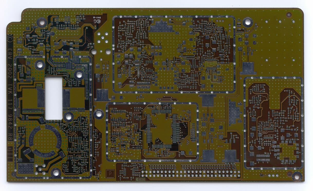
Click to zoom
Application Details
- Equipment Class
- TNB - Licensed Non-Broadcast Station Transmitter
- Date of Grant
- Apr 08, 2004
- Application Purpose
- Original Equipment
- Date of Application
- Feb 19, 2004
- Equipment Note
- BRU19 Mobitex Base Station
- Frequency Range
- 935.00000000 - 941.00000000
- Company
- Ericsson AB
- Country
- Sweden
Documents & Files
Document Text
Text extracted from the exhibit documents filed with the FCC. Open a document above to read the original.
Users Manual
Contents FBTEST Reference Manual BRU1/BRU3 MANUAL, Doc.no: b3fb_ref Uen Rev PJ5, 2004-02-19 1 Introduction ................................................................................................. 3 1.1Field of Application ......................................................................... 3 1.2Date and Time Window ................................................................... 4 1.3FBTEST Menu Overview ................................................................ 5 2 Installation Procedures .............................................................................. 10 3 Hardware, Equipment and Preparation...................................................... 11 3.1Configuration ................................................................................. 11 3.2External Tests requiring External Hardware.................................. 12 3.3Start of FBTEST ............................................................................ 12 4 FBTEST User Modes ................................................................................ 14 5 User Interface Description......................................................................... 15 5.1Working with Menus...................................................................... 15 5.1.1Toggling Function............................................................... 15 5.1.2Menu Displays .................................................................... 16 6 Main Menu ................................................................................................ 17 6.1Board Test Menu............................................................................ 20 6.1.1Alt. 1: Do the Test............................................................... 22 6.1.2Alt. 2: Number of Test Cycles ............................................ 22 6.1.3Alt. 3: Select/Unselect Boards ............................................ 23 6.1.4Alt. 4: Select Extended Test ............................................... 25 6.1.5Alt. 5: Select Medium Test ................................................. 25 6.1.6Alt. 6: Unselect all Tests..................................................... 25 6.1.7Alt. 7-11: Sets the Test Parameters for Each Board ........... 25 6.1.8Alt.7: Set Parameters for FCB – FE Computer Board........ 26 6.1.9Alt. 8: Set Parameters for FRB – FE Radio Board ............. 28 6.1.10 Alt. 9: Set Parameters for FNB – FE Connection Board (BRU3 only) ....................................................................... 29 6.1.11 Alt. 10 (BRU3): Set Parameters for FMB – FE Modem Board................................................................................... 30 BRU1/BRU3 MANUAL BRU1/BRU3 MANUAL, Doc.no: b3fb_ref Uen Rev PJ5, 2004-02-19 The contents of this document are subject to revision without notice due to continued progress in methodology, design and manufacturing. Ericsson shall have no liability for any errors or damages of any kind resulting from the use of this document. 6.1.12 Alt. 10 (BRU1): Set Parameters for FIB - FE Interface Board ...................................................................................31 6.1.13 Alt. 11: Set Params for FPB – FE Power Supply Board (BRU3 only) ........................................................................32 6.1.14 Alt.12: Look at Test Results ................................................33 6.2Set Time ..........................................................................................37 6.3Radio Operations ............................................................................38 6.3.1Radio Control and Calibration Menu ..................................38 6.3.2Transceiver Setup Menu ......................................................40 6.4Measurement Setup Menu ..............................................................45 6.4.1Transceiver Control and Presentation Menu .......................47 6.4.2Radio Calibration Menu ......................................................50 6.4.3Bandgap Calibration ............................................................52 6.4.4Temperature Sensor Calibration ..........................................54 6.4.5Reference Oscillator OCXO Calibration .............................56 6.4.6PF Output Power Calibration ..............................................59 6.4.7PR Reflected Power Calibration .........................................62 6.4.8VCO Modulation Calibration ..............................................65 6.4.9TCXO Modulation Calibration............................................69 6.4.10 RSSI Calibration..................................................................73 6.4.11 EEPROM Display Editor Menu ..........................................75 6.4.12 PA Bias and FDAC Calibration Menu ................................79 6.4.13 Radio Register Editor Menu ................................................81 6.4.14 Adjustment ..........................................................................82 6.4.15 Setup ....................................................................................85 6.5Modem Operation Menu (BRU3 only)...........................................87 6.6Interface Board Parameters Menu (BRU1 only) ............................88 6.6.1Configuration Data Display.................................................89 6.7Status Overview Menu....................................................................90 6.8Edit Loader Parameters Menu (BRU3 and System Release R14 only) ...........................................92 6.8.1Ports .....................................................................................94 6.8.2Channels ............................................................................102 6.8.3Connections .......................................................................105 6.8.4Read Parameters from FLASH..........................................107 6.9Store Parameters in FLASH ..................................................…
Text truncated - open the document above for the full version.
Users Manual
Contents 1 General ........................................................................................................ 3 2 About the BRU1 Manual ............................................................................. 4 3 Using the BRU1 Manual ............................................................................. 5 3.1Safety Instructions............................................................................ 5 3.2Site Requirements and Installation Instructions............................... 5 3.3Commissioning Procedure ............................................................... 6 3.4FBTEST Reference Manual ............................................................. 6 3.5Operation and Maintenance ............................................................. 6 4 Technical Data ............................................................................................. 7 4.1Power Requirements and Dimensions ............................................. 7 4.2Radio Parameters ............................................................................. 8 4.3Environmental Classifications ......................................................... 9 4.4Electromagnetic Compliance and Radio Standards ....................... 10 4.5Electrical Safety ............................................................................. 10 Introduction and Product Specification BRU1 MANUAL, Doc.no: b1intro Uen Rev PA2, 2004-02-17 BRU1 MANUAL BRU1 MANUAL, Doc.no: b1intro Uen Rev PA2, 2004-02-17 The contents of this document are subject to revision without notice due to continued progress in methodology, design and manufacturing. Ericsson shall have no liability for any errors or damages of any kind resulting from the use of this document. INTRODUCTION3 (10) BRU1 MANUAL, Doc.no: b1intro Uen Rev PA2, 2004-02-17 1General Radio Base Unit 1 (BRU1) is a complete one-channel compact radio base station which uses 8 kbps data signalling. The BRU1, which is intended for indoor operation, is a link between the mobile terminals (MOB) and the area exchanges (MOX) in the Mobitex Network. Figure 1 The front of Base Radio Unit 1 (BRU1). 94/1424-LZE 401 204 Rev A 4 (10)BRU1 MANUAL BRU1 MANUAL, Doc.no: b1intro Uen Rev PA2, 2004-02-17 2About the BRU1 Manual The BRU1 Manual is designed for engineering personnel who are familiar with data communications terminology and protocols and who will work on site with the BRU1. The Manual is intended for: •Operation and Maintenance personnel •Installation and Commissioning personnel •System engineers •Training BRU1 units may be damaged by mismanagement. Therefore, read the documents included in this manual carefully before you start operating the BRU1, especially the Safety Instructions document. It is important that this manual be available to all personnel working with the BRU1, and that the BRU1 is operated only by trained personnel. The manual provides the necessary information for installation, commissioning and operation of the BRU1, and contains the following documents: •Introduction and Product Specification (this document) •Safety Instructions •Site Requirements and Installation Instructions •Commissioning Procedure •FBTEST Reference Manual - complementary to the Commissioning Procedure. •Operation and Maintenance Instructions •End of Life Treatment INTRODUCTION5 (10) BRU1 MANUAL, Doc.no: b1intro Uen Rev PA2, 2004-02-17 3Using the BRU1 Manual Before using the BRU1 manual, you should have an overall understanding of how the Mobitex system operates as a wide-area packet switching network. If not, first refer to the NTE Client Library/System Library/System Manual. 3.1Safety Instructions The Safety Instructions document contains safety instructions for handling the BRU1 during installation and maintenance. It is recommended to read this document prior to reading the other documents, or starting any kind of installation or maintenance work. 3.2Site Requirements and Installation Instructions The Site Requirements and Installation Instructions document covers both the site preparations required, in terms of space, power, environment, cables, etc., and information required for a safe installation of the BRU1. 6 (10)BRU1 MANUAL BRU1 MANUAL, Doc.no: b1intro Uen Rev PA2, 2004-02-17 3.3Commissioning Procedure The Commissioning Procedure document includes two parts, the hardware and the software commissioning procedures. Hardware Commissioning describes how to put the BRU1 into operation after installation has been completed. Software Commissioning gives the necessary information for the commissioning of the BRU1 software. 3.4FBTEST Reference Manual The FBTEST Reference Manual describes the FBTEST test program which is used for the BRU1 hardware commissioning and some maintenance operations. 3.5Operation and Maintenance The Operation and Maintenance Instructions document informs about first-line operation and maintenance of the BRU1. The Design, Function and Operation chapter describes the design, function and operation of the BRU1 and its constituent parts. The Maintenance chapter describes how to carry out visual and preventive maintenance on the BRU1. The Troubleshooting chapter describes how to act if problems occur when operating the BRU1. Trouble shooting is always carried out in agreement with the NCC operator personnel. INTRODUCTION7 (10) BRU1 MANUAL, Doc.no: b1intro Uen Rev PA2, 2004-02-17 4Technical Data 4.1Power Requirements and Dimensions Power Requirements Dimension TitleProduct No. Rated Voltage (V DC) Power Consumption (W) 19BRU1 19-DHRB 10472/921 - 32<50 Height (mm)Width (mm)Depth (mm)Weight (kg) 19285 (TBC)344(TBC)101(TBC)<4.5 8 (10)BRU1 MANUAL BRU1 MANUAL, Doc.no: b1intro Uen Rev PA2, 2004-02-17 4.2Radio Parameters Radio data transmission speed= 8 kbps Modulation= Modified GMSK, BT = 0.3 Traffic mode= Duplex Channel bandwidth= 12.5 kHz Duplex spacing39MHz IF1 frequency77.25 kHz IF2 frequency450 kHz IF3 frequency42.31 kHz Rx frequency range896 - 902 M…
Text truncated - open the document above for the full version.
Users Manual
Contents 1 Design, Function and Operation .................................................................. 3 1.1General ............................................................................................. 3 1.2BRU1 connections and indicators .................................................... 4 1.3Start-Up and Shutdown Procedures ................................................. 6 1.3.1Start-Up Procedure ............................................................... 6 1.3.2Shutdown Procedure ............................................................. 6 1.3.3Restarting the BRU1 (Warm Start)....................................... 7 1.3.4Manual Restart of the BRU1 ................................................ 7 1.4Network Connections....................................................................... 8 1.4.1General.................................................................................. 8 1.5Alarms .............................................................................................. 9 2 Maintenance .............................................................................................. 10 2.1General ........................................................................................... 10 2.2Equipment Required....................................................................... 11 2.3Documentation Required ............................................................... 11 2.4Maintenance to be Performed ........................................................ 12 2.4.1Visual and Preventive Maintenance ................................... 12 2.5Function Check .............................................................................. 14 2.5.1General................................................................................ 14 2.5.2Equipment Required ........................................................... 14 2.5.3FBTEST Board Test ........................................................... 15 2.5.4Channel Unit Output Power................................................ 16 2.5.5Transmitter Deviation ......................................................... 17 2.5.6Bit Errors at high Signal Levels.......................................... 19 2.5.7Receiver Sensitivity ............................................................ 21 2.5.8Receiver Sensitivity at Frequency Deviation...................... 23 2.5.9Antenna input Signal .......................................................... 25 2.5.10 Hardware Alarm Status....................................................... 26 3 Troubleshooting......................................................................................... 28 3.1General ........................................................................................... 28 3.2Troubleshooting guide ................................................................... 29 Operation and Maintenance Instructions BRU1 MANUAL, Doc.no: b1opmain Uen Rev PA3 2004-02-20 BRU1 MANUAL BRU1 MANUAL, Doc.no: b1opmain Uen Rev PA3 2004-02-20 The contents of this document are subject to revision without notice due to continued progress in methodology, design and manufacturing. Ericsson shall have no liability for any errors or damages of any kind resulting from the use of this document. 3.2.1LED indicators.....................................................................29 OPERATION AND MAINTENANCE, BRU13 (30) BRU1 MANUAL, Doc.no: b1opmain Uen Rev PA3 2004-02-20 1Design, Function and Operation 1.1General Base Radio Unit 1 (BRU1) is a complete one-channel compact radio base station which uses 8 kbps data signalling. The BRU1, which is intended for indoor operation, is a link between the mobile terminals and the area exchanges in the Mobitex Network. All parts are integrated in the unit, see Figure 1. This section describes the design, function and operation of the BRU1. During normal operation, all actions necessary for the operation and check of the BRU1 are carried out at the Network Control Centre (NCC). When operating the BRU1 on site, the following equipment is required: Figure 1 BRU1 94/1424-LZE 401 204 Rev A 4 (30)BRU1 MANUAL BRU1 MANUAL, Doc.no: b1opmain Uen Rev PA3 2004-02-20 •Portable PC including VT-100 emulation software. •Console Cable TSRA 902 0190 (or equivalent) for connection of the terminal to the BRU1 connector "CONSOLE". •FBTEST For a description on how to connect the portable PC to the BRU1, please refer to chapter 1.3.2 “Shutdown Procedure”. 1.2BRU1 connections and indicators Figure 2 BRU1 external connections and indicators. 1.Ethernet Connection (and ethernet LED indicators) 2.Modem Connection RS232C 3.Modem Connection RS422B 4.Console Connection 5.LED indicators 6.Fuse 7.Power connector ERROR RS232 RS422 10BaseT SYSTEM OK CONSOLE RS422 RS232 POWERFUSE 3 A F +24 VDC Rx L 95/1424-LZE 401 204 Uen Rev A 1 2 3 4 5 6 7 OPERATION AND MAINTENANCE, BRU15 (30) BRU1 MANUAL, Doc.no: b1opmain Uen Rev PA3 2004-02-20 The table below gives a brief description of the BRU1 connections used. The position numbers found in the “Position” column refer to the corresponding position numbers in Figure 2. Pos.Connector Type of Connector Description 1EthernetRJ-45Connection to superior node via Ethernet 2RS-232C25p DSUB female Connection to superior node via RS232 3RS-422B25p DSUB female Connection to superior node via RS422B 4 Console9p DSUB female Connection used for Nodop terminal 5Quad LED indicator-System OK (green) Internal H/W Error (red) RS232 (yellow) RS422 (yellow) 6Fuse holder 7Power connector2p DSUBDC power input. +24V, 2A. 6 (30)BRU1 MANUAL BRU1 MANUAL, Doc.no: b1opmain Uen Rev PA3 2004-02-20 1.3Start-Up and Shutdown Procedures Note:When starting up the BRU1 after installation, follow the instructions in Node Hardware Library/BRU1/Commissioning Procedure. 1.3.1Start-Up Procedure When starting up the BRU1, do the following: 1.Connect the power cable to the BRU1. 2.Check that the ”System OK” green LED is lit. This indicates that all…
Text truncated - open the document above for the full version.
Users Manual
Contents Safety Instructions BRU1 MANUAL, Doc.no: b1saf_en Uen Rev PA1, 2004-02-20 1 Introduction ................................................................................................. 3 2 Safety Instructions ....................................................................................... 4 3 Precautions .................................................................................................. 6 3.1Radio Frequency Exposure .............................................................. 6 3.1.1RF Exposure Assessment by Calculation ............................. 7 3.2Electro Static Discharge (ESD)........................................................ 8 3.3Electrical Hazards ............................................................................ 8 3.3.1High Voltage......................................................................... 8 3.3.2Power Supply ........................................................................ 8 3.4Earthquakes ...................................................................................... 9 3.5Thunderstorms.................................................................................. 9 4 Rules and Requirements - US/Canada ...................................................... 10 4.1FCC - Rules and Requirements...................................................... 10 4.2BRU1 Classification....................................................................... 10 4.3BRU1 Interference ......................................................................... 10 4.4BRU1 Changes or Modifications ................................................... 11 BRU1 MANUAL BRU1 MANUAL, Doc.no: b1saf_en Uen Rev PA1, 2004-02-20 The contents of this document are subject to revision without notice due to continued progress in methodology, design and manufacturing. Ericsson shall have no liability for any errors or damages of any kind resulting from the use of this document. SAFETY INSTRUCTIONS3 (12) BRU1 MANUAL, Doc.no: b1saf_en Uen Rev PA1, 2004-02-20 1Introduction This section contains Safety Instructions for handling the Mobitex Base Radio Unit 1 (BRU1) during installation and maintenance work. Please read the Safety Instructions before starting any kind of installation or maintenance work. 4 (12)BRU1 MANUAL BRU1 MANUAL, Doc.no: b1saf_en Uen Rev PA1, 2004-02-20 2Safety Instructions Note:Reduce the risk of accidents by studying all the instructions carefully before starting work. If questions arise regarding the safety instructions, contact your supervisor or the local Ericsson company. Read and follow all warning notices and instructions found on the product or included in the BRU1 manual. Ericsson takes no responsibility if the labels have disappeared from a BRU1 due to accident or age. Where local regulations exist, these are to be followed. The safety information in this manual is a supplement to local regulations. It is the responsibility of the local project manager to make certain that local regulations are known and followed. The relevant manual (including this safety information) and specific instructions supplied by Ericsson must be followed in any work performed on the Ericsson products or systems. Sufficient knowledge of English or of any of the other languages in which the manuals or instructions are printed is necessary. The safety information in the relevant manuals presupposes that any person performing work on Ericsson products or systems has the necessary education, training and competence required in order to perform that work correctly. For certain work, additional training or special training may be required. For more precise information on the amount and content of the general and/or special training required for work on Ericsson products or systems, please contact the supervisor or the local Ericsson company. The slots and openings in the bottom of the BRU1 are provided for ventilation. To ensure reliable operation of the product and to protect it from overheating, these slots and openings must not be blocked or covered. When installed in the final configuration, the BRU1 must comply with the applicable safety standards and regulatory requirements of the country in which it is installed. If necessary, consult with the appropriate regulatory agencies and inspection authorities to ensure compliance. Definition of Expressions The following definitions of hazard degree are used in this document: SAFETY INSTRUCTIONS5 (12) BRU1 MANUAL, Doc.no: b1saf_en Uen Rev PA1, 2004-02-20 DANGER! Expresses a hazard that, if neglected, could be either fatal or cause life-long injuries to a human being, and/or destroy the equipment. WARNING! Expresses a hazard that, if neglected, could cause severe injuries to a human being, and/or severe damage to the equipment. CAUTION! Expresses a hazard that, if neglected, could cause injuries to a human being, or damage to equipment. 6 (12)BRU1 MANUAL BRU1 MANUAL, Doc.no: b1saf_en Uen Rev PA1, 2004-02-20 3Precautions 3.1Radio Frequency Exposure DANGER! The BRU1 is delivered with an antenna. Every installation of a BRU1 must maintain safety distances between radiating parts (for example, the antenna) and general public in order to meet applicable radio frequency exposure requirements under all circumstances of normal operation and service work being performed. BRU1 installation, and antenna connection should be performed only by professional personnel, with suitable qualification to assess potential radio frequency hazards. The BRU1 output power shall be considered. For RF safety considerations, users are not allowed to approach close to the antenna (see chapter 3.1.1 below) WARNING! To avoid discomfort due to the local heating effect of radio frequency, do not touch the antenna when the BRU1 is transmitting DANGER! Do not operate the BRU1 in an explosive atmosphere. Operating where explosive gas is present may result in an explosion. SAFETY INSTRUCTIONS7 (12) BRU1 MANUAL, Doc.no: b1saf_en Uen R…
Text truncated - open the document above for the full version.
Users Manual
Contents 1 General ........................................................................................................ 3 1.1Commissioning ................................................................................ 3 1.2Function Check ................................................................................ 4 2 Hardware Commissioning ........................................................................... 5 2.1General ............................................................................................. 5 2.2Test Equipment ................................................................................ 5 2.3Documentation Required ................................................................. 5 3 Part A - Installation Inspection .................................................................... 6 4 Part B - Power Test...................................................................................... 7 5 Part C - Transmitter Test ............................................................................. 8 5.1C1 - Reference Oscillator................................................................. 8 6 Part D- Hardware Alarms .......................................................................... 10 6.1D1 - Alarm Status........................................................................... 10 7 Part E- LED indicators .............................................................................. 12 7.1E1 - LED indicators ....................................................................... 12 8 Before Leaving the Site ............................................................................. 13 9 Software Commissioning .......................................................................... 14 9.1General ........................................................................................... 14 9.2Equipment Required....................................................................... 14 9.3Connecting the BRU1 .................................................................... 15 9.3.1Connection Procedure......................................................... 15 9.3.2NODOP............................................................................... 15 9.3.3Console ............................................................................... 15 9.4Installation of BRU1 Software....................................................... 15 10 Commissioning Procedure......................................................................... 19 10.1 Part SW-A - Commissioning the Computer................................... 19 10.2 Part SW-B - Network Test ............................................................. 20 10.3 Part SW-C - Traffic Test ................................................................ 21 Commissioning Procedure BRU1 MANUAL, Doc.no: b1commis Uen Rev PA5, 2004-02-20 BRU1 MANUAL BRU1 MANUAL, Doc.no: b1commis Uen Rev PA5, 2004-02-20 The contents of this document are subject to revision without notice due to continued progress in methodology, design and manufacturing. Ericsson shall have no liability for any errors or damages of any kind resulting from the use of this document. 11 Before Leaving the Site..............................................................................22 12 Appendix 1 Downloading New MAIN NTE SW to a BRU1 Node ....................................23 COMMISSIONING PROCEDURE3 (23) BRU1 MANUAL, Doc.no: b1commis Uen Rev PA5, 2004-02-20 1General 1.1Commissioning The commissioning is divided into two parts. This first part describes the HW (Hardware) Commissioning Procedure for the Base Radio Unit 1 (BRU1) and the second part describes the SW (Software) Commissioning Procedure. After installation of the BRU1, it is recommended to carry out the tests described below on site. The test procedures described in this section require that the installation has been successfully completed in accordance with the installation instructions found in Node Hardware Library/BRU1/Site Requirements and Installation Instructions. When performing the hardware commissioning procedure, the following documents are also required: •Node Hardware Library/BRU1/FBTEST Reference Manual •Node Software Library •BRU1 - Site Documentation Note: The Site Documentation is not included in the electronically published version of the Mobitex NTE Client Library but is delivered on paper together with the hardware. The results of the commissioning are entered in the Commissioning Test Record included in the BRU1 - Site Documentation. Each check or test described below has a specific name. After each check has been carried out, the corresponding check box in the Commissioning Test Record is to be completed by entering the value of the test result, or for some tests, just by selecting the check box. If the result of the commissioning procedure does not correspond with the information given in this document, or if a malfunction is suspected, please refer to Node Hardware Library/BRU1/Operation and Maintenance Instructions/Troubleshooting. 4 (23)BRU1 MANUAL BRU1 MANUAL, Doc.no: b1commis Uen Rev PA5, 2004-02-20 1.2Function Check If required by the operator, the Function Check described in Node Hardware Library/BRU1/Operation and Maintenance Instructions, may be used as an extended hardware commissioning test. COMMISSIONING PROCEDURE5 (23) BRU1 MANUAL, Doc.no: b1commis Uen Rev PA5, 2004-02-20 2Hardware Commissioning 2.1General The test equipment listed below is required when carrying out hardware commissioning procedure. Other equivalent test equipment may be used instead if performance and tolerances meet the specifications stated below. Note:The test instruments should be properly calibrated as any inaccuracy in the instruments may deteriorate system quality. 2.2Test Equipment The following equipment is required when carrying out hardware commissioning of the BRU1: •Portable PC including VT-100 emulation software •BRU3 Console Cable TSRA 902…
Text truncated - open the document above for the full version.
Contact Information
Applicant
Reinhold Reul(Project Manager)
Technical Contact
Ericsson ABCarl-Gunnar Sjoeberg
[email protected]+46-31-747-4540
Lindholmspiren 11 · Gothenburg · Sweden
Non-Technical Contact
Ericsson ABCarl-Gunnar Sjoeberg
[email protected]+46-31-747-4540
Technical Specifications
| # | Rule Parts | Frequency Range | Power Output | Emission | Tolerance |
|---|---|---|---|---|---|
| 1 | 90 | 935 MHz - 941 MHz | 1 W | 12K2F1D | 100.0000000000 Hz |
Other Applications from Ericsson AB

OSB-BRU3902
Oct 29, 2003BRU3902 Mobitex Base Station
Equipment Class
TNB - Licensed Non-Broadcast Station Transmitter
OSBM3090-MOBITEX
Feb 09, 2000Radio Modem
Equipment Class
TNB - Licensed Non-Broadcast Station Transmitter