OSEALRUCommand unit (RF button) to control laparoscopic camera
Medical Surgery Technologies Ltd.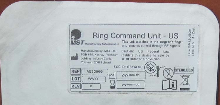
Click to zoom
Application Details
- Equipment Class
- DSR - Part 15 Remote Control/Security Device Transceiver
- Date of Grant
- Jan 01, 2013
- Application Purpose
- Original Equipment
- Date of Application
- Jan 01, 2013
- Equipment Note
- Command unit (RF button) to control laparoscopic camera
- Frequency Range
- 915.90000000 - 915.90000000
- Country
- Israel
Documents & Files
Document Text
Text extracted from the exhibit documents filed with the FCC. Open a document above to read the original.
Users Manual
CU – User Manual Command Unit (CU) For AutoLap User Manual 1023 CU – User Manual - DRAFT CU-90-089 ver 03, 24-Dec-2012 Page2 Device name Command Unit Clip EU Part Number: ASS02001 Command Unit Clip US Part Number: ASS03001 Command Unit Ring EU Part Number: ASS04001 Command Unit Ring US Part Number: ASS05001 Manufactured by: MST – Medical Surgery Technologies Kochav Yokneam Building, Floor 5, P.O.B 685 Industrial Center, Yokneam Illit 20692 Israel : +972(0)73-7965570 : +972(0)73-7965571 : [email protected] European Representative: EC REP Donawa Lifescience Consulting Srl Piazza Albania, 10 00153 Rome, Italy Copyright © 2012 by MST – Medical Surgery Technologies All rights reserved. You are not permitted to reproduce or transmit this document (or part of this document) in any format or by any means, without written approval of the MST Company . MODIFICATIONS The information presented in this document may be modified without warning. Maximum effort has been made to guarantee the accuracy of the information provided in this document . LICENSE CONTRACT AutoLap CU design is the exclusive property of the MST Company. Any copying either in part or in whole is strictly prohibited. CU – User Manual - DRAFT CU-90-089 ver 03, 24-Dec-2012 Page3 Table of Contents CHAPTER 1. General ................................................................................................ 4 1.1 Introduction ...................................................................................................... 4 1.2 Scope of This Manual ...................................................................................... 4 1.3 Conventions Used in this Manual .................................................................... 4 CHAPTER 2. About the CU ....................................................................................... 6 2.1 Intended Use ................................................................................................... 6 2.2 The CU Modes of operation ............................................................................ 6 2.3 The CU Configurations .................................................................................... 6 CHAPTER 3. Contents of the Sterile Package .......................................................... 8 CHAPTER 4. Handling ............................................................................................ 10 4.1 On Receipt of Package ................................................................................. 10 4.2 Storage .......................................................................................................... 10 4.3 Summary of Warnings and Precautions ........................................................ 10 CHAPTER 5. Technical Characteristics .................................................................. 11 CHAPTER 6. CU Operation ..................................................................................... 11 6.1 Attaching the CU to finger or tool .................................................................. 11 CU – User Manual - DRAFT CU-90-089 ver 03, 24-Dec-2012 Page4 CHAPTER 1. General 1.1 Introduction This manual is an accompanying document to the Command Unit (CU) – control components of the AutoLap system. The AutoLap system is designed to hold and control the movement of the laparoscope during laparoscopic surgeries. It describes the Command Unit, as well as its functioning as part of the AutoLap system. 1.2 Scope of This Manual The scope of this user manual is to provide the safety information of the product, and to explain the basic operating instructions that are performed by the system’s user. 1.3 Conventions Used in this Manual The following symbols and conventions are used in this manual: Note Notes provide plain good advice and/or additional information of which the user should be aware. A note is located next to the relevant text and should not be used for direct action. Caution Alerts the user to a possible problem with the device concerning its use or misuse. Such problems include device malfunction, device failure, damage to the device or damage to other property. The caution statement includes the precaution that should be taken to avoid the hazard. Warning Alerts the user to the possibility of injury, death, or other serious adverse reactions associated with the use or misuse of the device. CU – User Manual - DRAFT CU-90-089 ver 03, 24-Dec-2012 Page5 Explanation of Shortcuts in this manual user: CU – Command Unit DOF – Degree Of Freedom OR – Operating Room EMC – Electromagnetic Compatibility IEC – International Electrotechnical Committee CU – User Manual - DRAFT CU-90-089 ver 03, 24-Dec-2012 Page6 CHAPTER 2. About the CU 2.1 Intended Use The Command Unit (CU) is a sterile disposable unit that is designed to transmit low power RF signals. The main functions of the RF signals are to enable the movement of the laparoscope to the surgeon's desired location. 2.2 The CU Modes of operation The CU is designed to control the movement of the laparoscope at the discretion of the surgeon. Pressing the button of the CU will start the movement of the laparoscope. When the surgeon stops pressing the button, the movement is stopped. The CU contains a Five-Way Button. Pressing the button in its different modes enables the AutoLap to move the laparoscope up or down as presented on the surgeon's screen, move the laparoscope to the right or to the left of the screen, advance the laparoscope into the patient's abdomen (zoom in) or extract it from the patient's abdomen (zoom out). 2.3 The CU Configurations The CU is designed in two configurations : 1. Ring, which is worn by the surgeon on one of his fingers (like a normal ring), over the glove. The Ring Unit is activated with the surgeon's thumb. See Figure 1. Figure 1: CU Ring configuration CU – User Manual - DRAFT CU-90-089 ver 03, 24-Dec-2012 Page7 2. Clip, which is connected to the surgical tool. The Clip Unit is activated with …
Text truncated - open the document above for the full version.
Cover Letter(s)
RF_160, Issue 03 Declaration of Authorization We Name: Medical Surgery Technologies Ltd. (MST) Address: Kochav Yokneam Building, P.O.B. 685 City: Yokneam 20692 Country: Israel Declare that: Name Representative of agent: ............. (1) Agent Company name: Hermon Laboratories Ltd. . Address: Harakevet Industrial Zone .. City: Binyamina 30500 .. Country Israel . is authorized to apply for Certification of the following product(s): Product description: RF Button (Command Unit) to control the holding and positioning of laparoscopic camera Type designation: 1) CU Ring ASS05000; 2) CU Clip ASS03000 Trademark: MST on our behalf. Date: December 10, 2012 City: Yokneam Name: Alon Shacham (2) Function: VP R&D Signature: Notes: (1): Required for FCC application (2): For FCC it must be the Grantee Code “owner” or the authorized agent.
Cover Letter(s)
FCC, Request for non-disclosure Date: 16-Jul-10 RF_501, Issue 6 Page 1 of 1 Company Name: Medical Surgery Technologies Ltd. (MST) Address : Kochav Yokneam Building, P.O.B. 685 City: Yokneam 20692 Country: Israel To: Telefication B.V., Dept. FCC TCB Edisonstraat 12A 6902 PK ZEVENAAR The Netherlands Subject: Request for confidentiality FCC ID: OSEALRU Reference number: ###### Dear FCC TCB, 1. Long-Term Confidentiality Pursuant to 47 CFR Section 0.459(a) & (b), we hereby requests non-disclosure and confidential treatment of the following materials submitted in support of FCC certification application: Bill(s) of Material Block Diagrams Operational Description Schematic Diagrams Tune-up Procedure Above materials contain secrets, proprietary and technical information, which would customarily be guarded from competitors under 47 CFR, section 0.457(d)(2). Disclosure or publication or any portion of this company confidential material to other parties could cause substantial competitive harm and provide unjustified benefits for competitors. 2. Short-Term Confidentiality (STC) Pursuant to Public Notice DA 04-1705 of the Commission’s policy, in order to comply with the marketing regulations in 47 CFR §2.803 and the importation rules in 47 CFR §2.1204, a pplicant hereby requests Short-Term Confidential treatment of the following materials (note 1): Internal Photos User’s Manual Test Set-up Photos External Photos Justification: Planned Release Date STC: (notes 2, 3, 4, 5) Date: December 10, 2012 Name and signature of applicant: Alon Shacham Notes: 1) A document or type of document can only have ONE type of confidentiality! 2) Short-Term confidentiality is in principle for 45 days from date of grant; it can be extended max 3 times (total time 180 days max.)! 3) FCC must be informed when marketing begins earlier. 4) Release takes place automatically thus extension must be requested in time. Telefication does not remind you of this! 5) Request for extension or for release must be received by Telefication at least 7 days before date of actual marketing or before expiration of the STC period
External Photos
Medical Surgery Technologies Ltd. FCC ID:OSEALRU Page 1 of 6 EXTERNAL PHOTOGRAPHS This document contains 5 photographs Medical Surgery Technologies Ltd. FCC ID:OSEALRU Page 2 of 6 Photograph No.1 AutoLap CU Ring general view with package cover Medical Surgery Technologies Ltd. FCC ID:OSEALRU Page 3 of 6 Photograph No.2 AutoLap CU Ring cover rear side Medical Surgery Technologies Ltd. FCC ID:OSEALRU Page 4 of 6 Photograph No.3 AutoLap CU Ring general view Medical Surgery Technologies Ltd. FCC ID:OSEALRU Page 5 of 6 Photograph No.4 AutoLap CU Ring side view Medical Surgery Technologies Ltd. FCC ID:OSEALRU Page 6 of 6 Photograph No.5 AutoLap CU Ring rear side view
ID Label/Location Info
Medical Surgery Technologies Ltd. FCC ID:OSEALRU Page 1 of 1 LABEL LABEL LOCATION The label is located on the rear cover of the CU Ring packaging due to very small dimensions of the device. The justification letter “Label_justification_22764” attached to this Application for certification. The statement according to FCC part 15 §15.19(a)(3) is placed in User Manual, page 7 (Application exhibit User_manual_22764).
ID Label/Location Info
Page 1 of 2 Marking the CU RING with FCC ID:OSEALRU Photographs of the exterior appearance of the CU Ring and its packaging are provided. The FCC identifier and a label will not be placed on the device itself for two reasons. First, the CU Ring is so small as to make placing the label on it is impracticable (Photograph 1). Second, the CU Ring is a disposable unit, will be always within its packaging including the time of purchase, until the time of use in a sterile environment. Having the label on the CU Ring would be of little use. Photograph 1: AutoLap CU Ring general view Page 2 of 2 Photograph 2: AutoLap CU Ring back cover with a label Therefore, consistent with FCC 47CFR § 2.925(f) the Applicant proposes as an alternative method of affixing the label, to affix it to the CU Ring packaging as shown in the photograph above and in the accompanying User Manual, provided as a separate exhibit to this application. Sincerely, Alon Shacham, VP R&D Medical Surgery Technologies Ltd.
Internal Photos
Medical Surgery Technologies Ltd. FCC ID:OSEALRU Page 1 of 4 INTERNAL PHOTOGRAPHS This document contains 3 photographs Medical Surgery Technologies Ltd. FCC ID:OSEALRU Page 2 of 4 Photograph No.1 CU Ring internal view Medical Surgery Technologies Ltd. FCC ID:OSEALRU Page 3 of 4 Photograph No.2 CU Ring PCBs top view Medical Surgery Technologies Ltd. FCC ID:OSEALRU Page 4 of 4 Photograph No.3 CU Ring PCBs second side view
Operational Description
Page 1 of 1 FCC ID:OSEALRU Description of the AutoLap command unit, model CU Ring The AutoLap system is designed to hold and position the laparoscope during laparoscopic surgery. When the camera is in position, the AutoLap system holds it in a stable manner. When the surgeon wishes to change the camera's position, the system positions the laparoscopic camera by maneuvering the laparoscope using a joystick. The movement of the laparoscopic camera is enabled and disabled by the surgeon. The Command Unit (CU) is a sterile disposable unit that is designed to transmit low power RF signals. The main functions of the RF signals are to enable the movement of the laparoscope to the surgeon's desired location. The CU Ring is worn by the surgeon on one of his fingers (like a normal ring) over the glove. The surgeon uses the AutoLap Command Unit (CU Ring) to control the laparoscope. Typical use of the CU Ring is: Before the Laparoscopic surgery starts, the CU Ring will transmit a signal to be registered to the system. The transmitter operates at 915.9 MHz. After the surgeon attaches the laparoscope to the AutoLap, movement of the laparoscope is enabled by the CU Ring or using the manual activation button. The AutoLap CU Ring is a manual operated device, with software controlled functions. Once the device is triggered, a pre-programmed cycle of less than 900 μsec transmission occurs.
Test Report
Hermon Laboratories Ltd. Harakevet Industrial Zone, Binyamina 30500, Israel Tel. +972-4-6288001 Fax. +972-4-6288277 E-mail: [email protected] Page 1 of 51 Report ID: MSTRAD_FCC.22832.doc Date of Issue: 23-Apr-12 ELECTRICAL TESTING 0839.01 TEST REPORT ACCORDING TO: FCC CFR 47 Part 15 subpart C, section 15.231(a) and subpart B, RSS-210 issue 8 Annex 1 FOR: Medical Surgery Technologies Ltd. (MST) Command Unit (CU) for the AutoLap System Model: CU Clip Model number: ASS03000 FCC ID:OSEALCU This report is in conformity with ISO/ IEC 17025. The "A2LA Accredited" symbol endorsement applies only to the tests and calibrations that are listed in the scope of Hermon Laboratories accreditation. The test results relate only to the items tested. This test report shall not be reproduced in any form except in full with the written approval of Hermon Laboratories Ltd. Report ID: MSTRAD_FCC.22832.doc Date of Issue: 23-Apr-12 Page 2 of 51 Table of contents 1 Applicant information ..................................................................................................................................................... 3 2 Equipment under test attributes .................................................................................................................................... 3 3 Manufacturer information .............................................................................................................................................. 3 4 Test details .................................................................................................................................................................... 3 5 Tests summary .............................................................................................................................................................. 4 6 EUT description ............................................................................................................................................................. 5 6.1 General information ....................................................................................................................................................... 5 6.2 Test configuration .......................................................................................................................................................... 5 6.3 Changes made in EUT .................................................................................................................................................. 5 6.4 EUT test positions ......................................................................................................................................................... 6 6.5 Transmitter characteristics ............................................................................................................................................ 7 7 Transmitter tests according to 47CFR part 15 subpart C and RSS-210 Annex 1 requirements .................................... 8 7.1 Periodic operation requirements ................................................................................................................................... 8 7.2 Field strength of emissions .......................................................................................................................................... 10 7.3 Occupied bandwidth test ............................................................................................................................................. 33 7.4 Antenna requirements ................................................................................................................................................. 36 8 Unintentional emissions .............................................................................................................................................. 37 8.1 Radiated emission measurements .............................................................................................................................. 37 9 APPENDIX A Test equipment and ancillaries used for tests ....................................................................................... 43 10 APPENDIX B Measurement uncertainties ................................................................................................................... 44 11 APPENDIX C Test laboratory description ................................................................................................................... 45 12 APPENDIX D Specification references ....................................................................................................................... 45 13 APPENDIX E Test equipment correction factors ......................................................................................................... 46 14 APPENDIX F Abbreviations and acronyms ................................................................................................................. 51 Report ID: MSTRAD_FCC.22832.doc Date of Issue: 23-Apr-12 Page 3 of 51 1 Applicant information Client name: Medical Surgery Technologies Ltd. (MST) Address: P.O.Box 685, Yokneam 20692, Israel Telephone: +972 (73) 7965570 Fax: +972 (73) 7965571 E-mail: [email protected] Contact name: Mr. Alon Shacham 2 Equipment under test attributes Product name: Command Unit (CU) for the AutoLap System Product type: Transmitter operating at 915.9 MHz Model(s): CU Clip Model number: ASS03000 Serial number: 75 Hardware version: 1.0 Software release: 1.0 Receipt date 12/18/2011 3 Manufacturer information Manufacturer name: Medical Surgery Technologies Ltd. (MST) Address: P.O.Box 685, Yokneam 20692, Israel Telephone: +972 (73) 7965570 Fax: +972 (73) 7965571 E-Mail: [email protected] Contact name: Mr. Alon Shacham 4 Test details Project ID: 22832 Location: Hermon Laboratories Ltd. Harakevet Industrial Zone, Binyamina 30500, Israel Test started: 12/18/2011 Test completed: 1/10/2012 Test specification(s): FCC 47CF…
Text truncated - open the document above for the full version.
Test Report
Hermon Laboratories Ltd. Harakevet Industrial Zone, Binyamina 30500, Israel Tel. +972-4-6288001 Fax. +972-4-6288277 E-mail: [email protected] Page 1 of 51 Report ID: MSTRAD_FCC.22832.doc Date of Issue: 23-Apr-12 ELECTRICAL TESTING 0839.01 TEST REPORT ACCORDING TO: FCC CFR 47 Part 15 subpart C, section 15.231(a) and subpart B, RSS-210 issue 8 Annex 1 FOR: Medical Surgery Technologies Ltd. (MST) Command Unit (CU) for the AutoLap System Model: CU Clip Model number: ASS03000 FCC ID:OSEALCU This report is in conformity with ISO/ IEC 17025. The "A2LA Accredited" symbol endorsement applies only to the tests and calibrations that are listed in the scope of Hermon Laboratories accreditation. The test results relate only to the items tested. This test report shall not be reproduced in any form except in full with the written approval of Hermon Laboratories Ltd. Report ID: MSTRAD_FCC.22832.doc Date of Issue: 23-Apr-12 Page 2 of 51 Table of contents 1 Applicant information ..................................................................................................................................................... 3 2 Equipment under test attributes .................................................................................................................................... 3 3 Manufacturer information .............................................................................................................................................. 3 4 Test details .................................................................................................................................................................... 3 5 Tests summary .............................................................................................................................................................. 4 6 EUT description ............................................................................................................................................................. 5 6.1 General information ....................................................................................................................................................... 5 6.2 Test configuration .......................................................................................................................................................... 5 6.3 Changes made in EUT .................................................................................................................................................. 5 6.4 EUT test positions ......................................................................................................................................................... 6 6.5 Transmitter characteristics ............................................................................................................................................ 7 7 Transmitter tests according to 47CFR part 15 subpart C and RSS-210 Annex 1 requirements .................................... 8 7.1 Periodic operation requirements ................................................................................................................................... 8 7.2 Field strength of emissions .......................................................................................................................................... 10 7.3 Occupied bandwidth test ............................................................................................................................................. 33 7.4 Antenna requirements ................................................................................................................................................. 36 8 Unintentional emissions .............................................................................................................................................. 37 8.1 Radiated emission measurements .............................................................................................................................. 37 9 APPENDIX A Test equipment and ancillaries used for tests ....................................................................................... 43 10 APPENDIX B Measurement uncertainties ................................................................................................................... 44 11 APPENDIX C Test laboratory description ................................................................................................................... 45 12 APPENDIX D Specification references ....................................................................................................................... 45 13 APPENDIX E Test equipment correction factors ......................................................................................................... 46 14 APPENDIX F Abbreviations and acronyms ................................................................................................................. 51 Report ID: MSTRAD_FCC.22832.doc Date of Issue: 23-Apr-12 Page 3 of 51 1 Applicant information Client name: Medical Surgery Technologies Ltd. (MST) Address: P.O.Box 685, Yokneam 20692, Israel Telephone: +972 (73) 7965570 Fax: +972 (73) 7965571 E-mail: [email protected] Contact name: Mr. Alon Shacham 2 Equipment under test attributes Product name: Command Unit (CU) for the AutoLap System Product type: Transmitter operating at 915.9 MHz Model(s): CU Clip Model number: ASS03000 Serial number: 75 Hardware version: 1.0 Software release: 1.0 Receipt date 12/18/2011 3 Manufacturer information Manufacturer name: Medical Surgery Technologies Ltd. (MST) Address: P.O.Box 685, Yokneam 20692, Israel Telephone: +972 (73) 7965570 Fax: +972 (73) 7965571 E-Mail: [email protected] Contact name: Mr. Alon Shacham 4 Test details Project ID: 22832 Location: Hermon Laboratories Ltd. Harakevet Industrial Zone, Binyamina 30500, Israel Test started: 12/18/2011 Test completed: 1/10/2012 Test specification(s): FCC 47CF…
Text truncated - open the document above for the full version.
Test Setup Photos
Medical Surgery Technologies Ltd. FCC ID:OSEALRU Page 1 of 5 SETUP PHOTOGRAPHS This document contains 4 photographs Medical Surgery Technologies Ltd. FCC ID:OSEALRU Page 2 of 5 Photograph No.1 Setup for spurious emission field strength measurements in the anechoic chamber below 30 MHz Medical Surgery Technologies Ltd. FCC ID:OSEALRU Page 3 of 5 Photograph No.2 Setup for spurious emission field strength measurements in the anechoic chamber in 30 – 1000 MHz range Medical Surgery Technologies Ltd. FCC ID:OSEALRU Page 4 of 5 Photograph No.3 Setup for spurious emission field strength measurements in the anechoic chamber above 1000 MHz Medical Surgery Technologies Ltd. FCC ID:OSEALRU Page 5 of 5 Photograph No.4 Setup for occupied bandwidth measurements
Test Setup Photos
Medical Surgery Technologies Ltd. FCC ID:OSEALRU Page 1 of 5 SETUP PHOTOGRAPHS This document contains 4 photographs Medical Surgery Technologies Ltd. FCC ID:OSEALRU Page 2 of 5 Photograph No.1 Setup for spurious emission field strength measurements in the anechoic chamber below 30 MHz Medical Surgery Technologies Ltd. FCC ID:OSEALRU Page 3 of 5 Photograph No.2 Setup for spurious emission field strength measurements in the anechoic chamber in 30 – 1000 MHz range Medical Surgery Technologies Ltd. FCC ID:OSEALRU Page 4 of 5 Photograph No.3 Setup for spurious emission field strength measurements in the anechoic chamber above 1000 MHz Medical Surgery Technologies Ltd. FCC ID:OSEALRU Page 5 of 5 Photograph No.4 Setup for occupied bandwidth measurements
Contact Information
Applicant
Gal Atarot(VP R&D)
Technical Contact
Test Firm
Hermon Laboratories Ltd.Alexander Usoskin
Technical Specifications
| # | Rule Parts | Frequency Range | Power Output |
|---|---|---|---|
| 1 | 15.231 | 915.9 MHz - 915.9 MHz | - |
Other Applications from Medical Surgery Technologies Ltd.
OSEALCU
Jan 01, 2013Command unit (RF button) to control laparoscopic camera
Equipment Class
DSR - Part 15 Remote Control/Security Device Transceiver