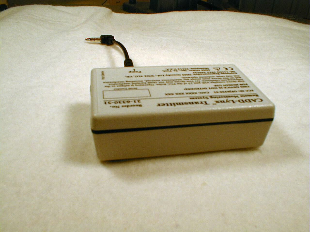
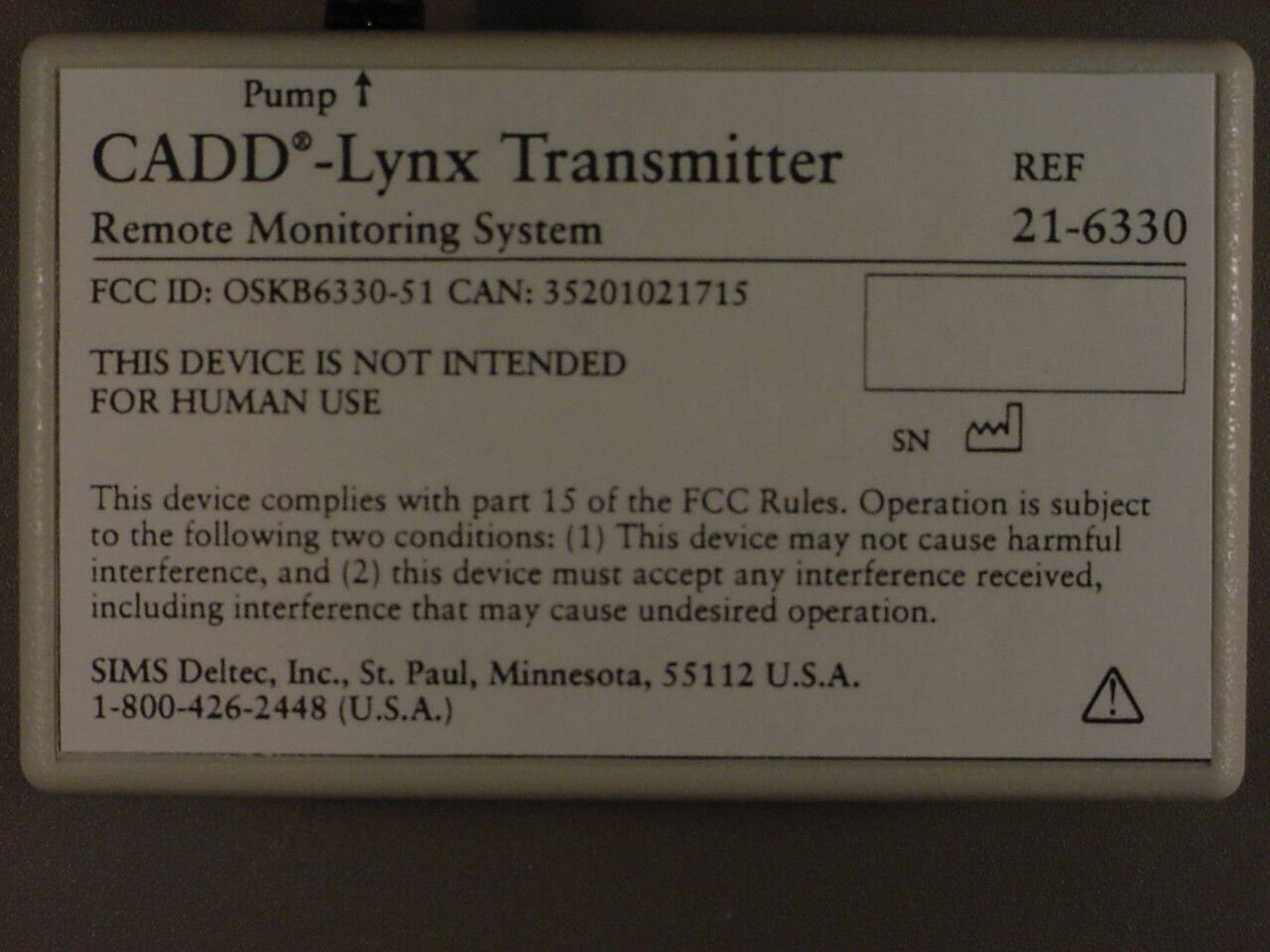
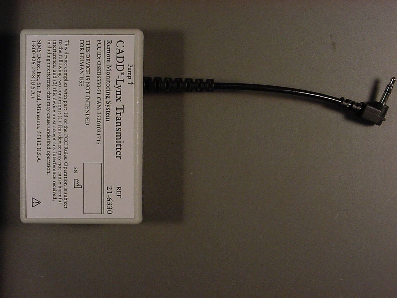
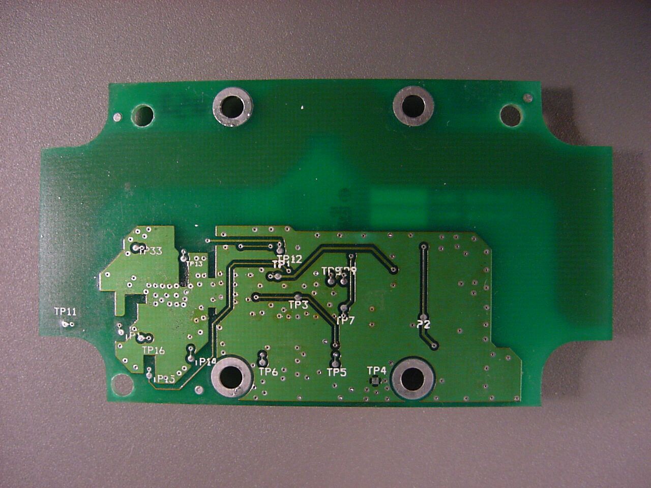
OSKB6330-51Wireless Remote Monitoring System (WRMS) Transmitt
SIMS Deltec, Inc.
Click to zoom
Application Details
- Equipment Class
- DSC - Part 15 Security/Remote Control Transmitter
- Date of Grant
- Dec 21, 2000
- Application Purpose
- Original Equipment
- Date of Application
- Nov 14, 2000
- Equipment Note
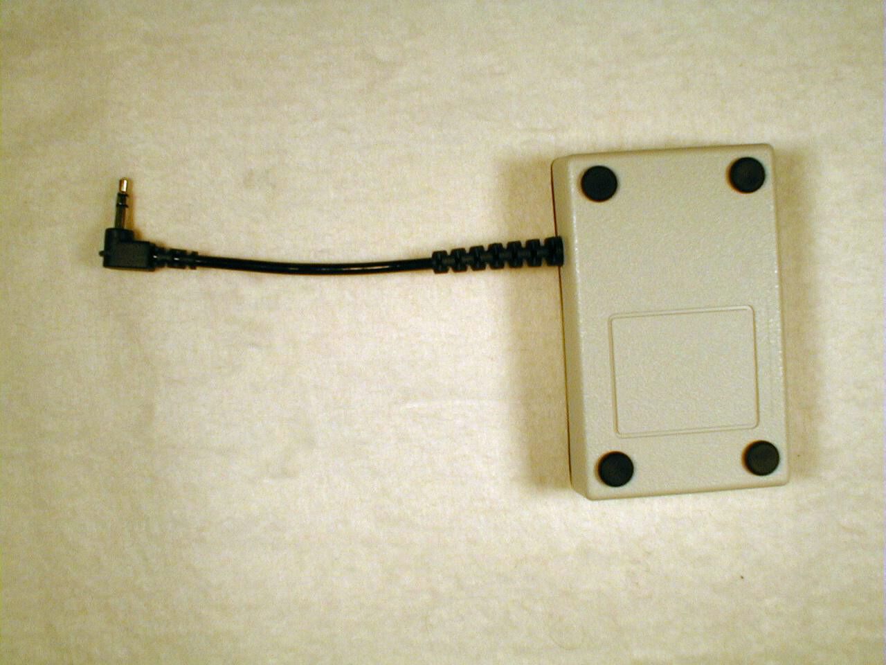
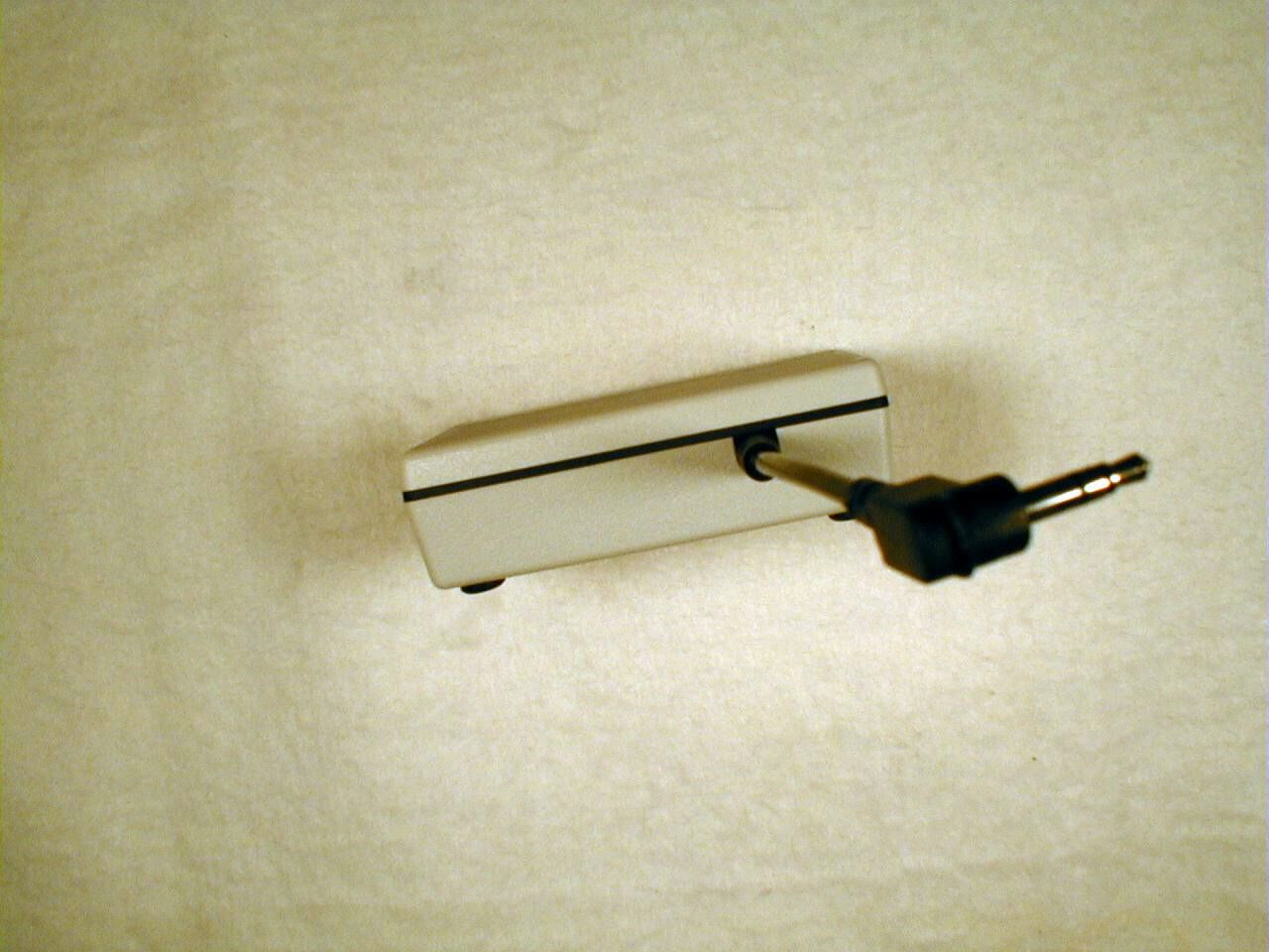
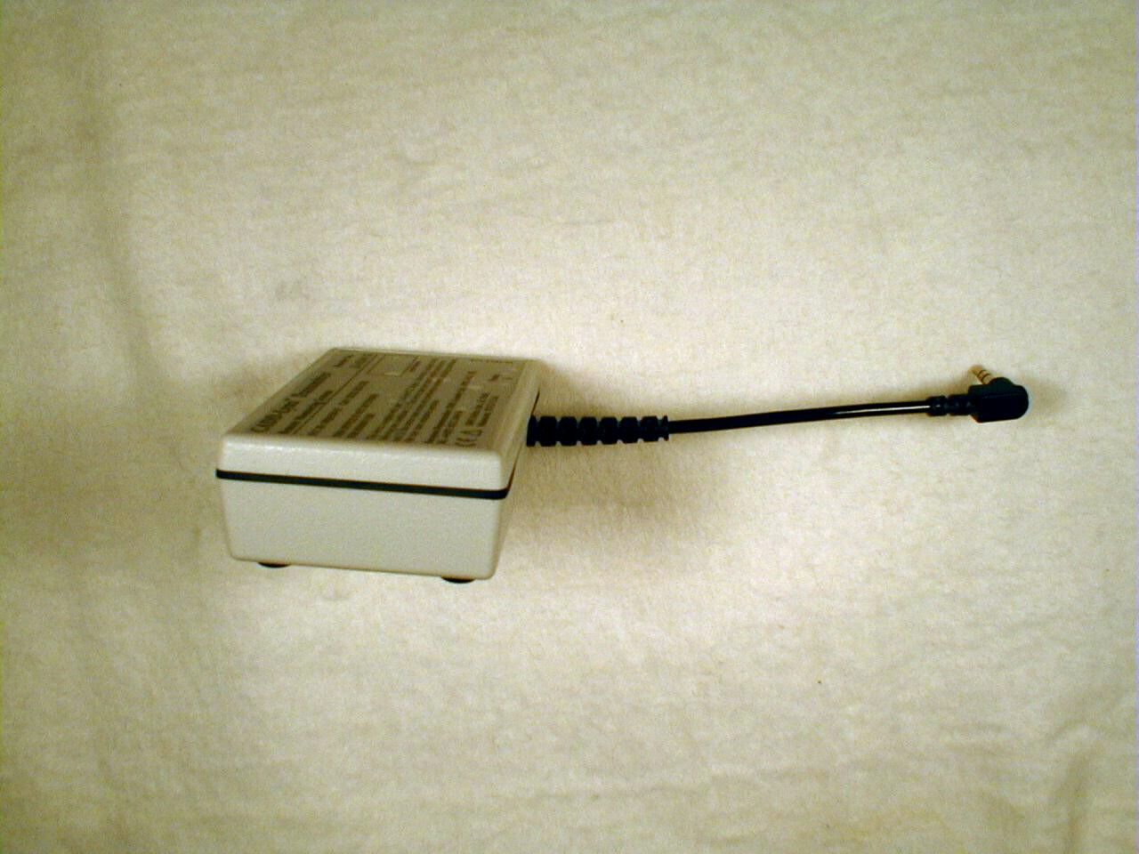
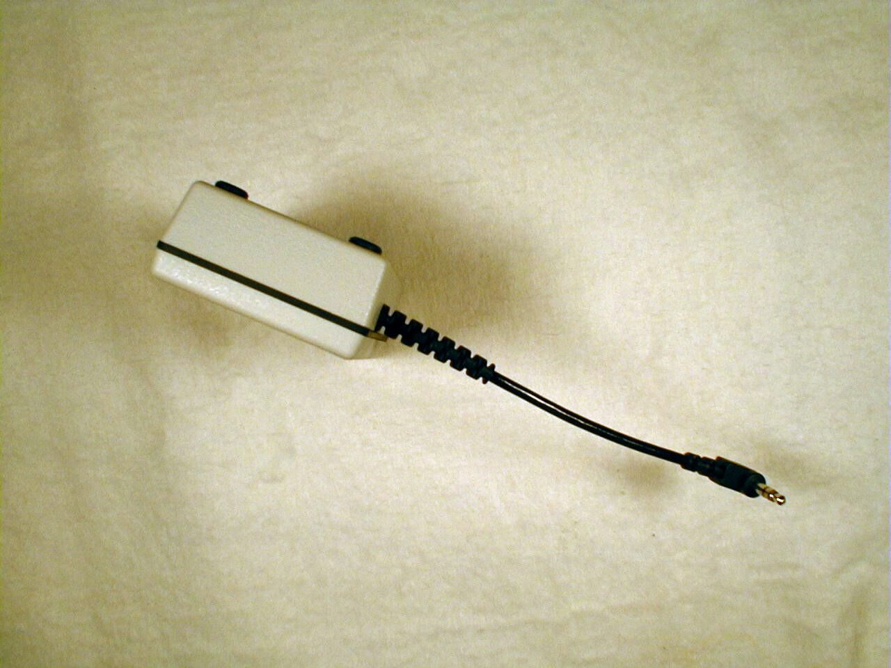
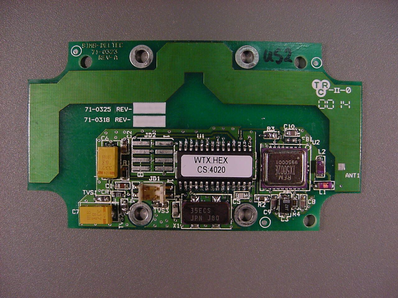
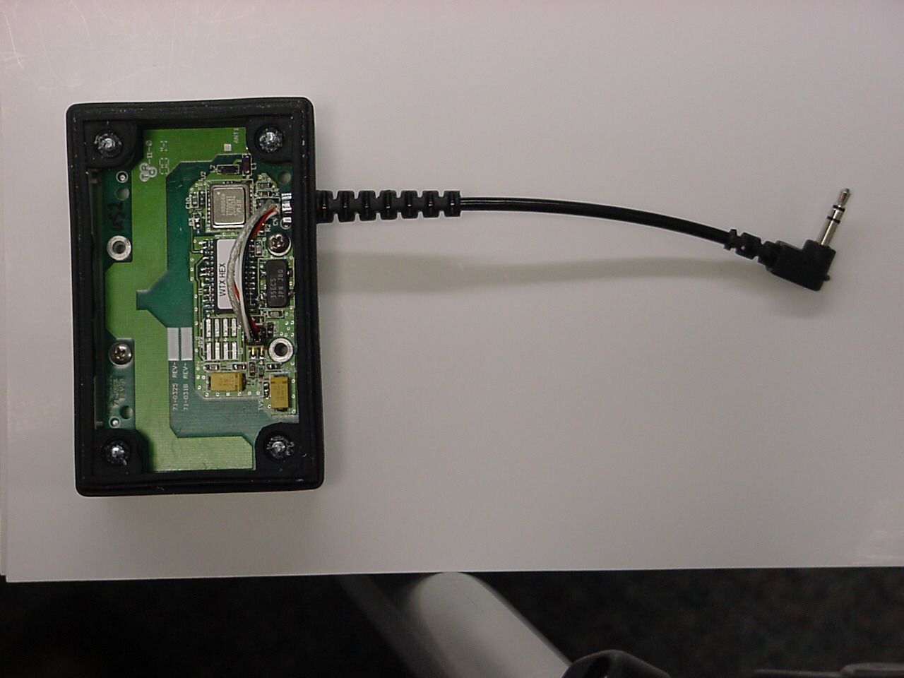
- Wireless Remote Monitoring System (WRMS) Transmitt
- Frequency Range
- 418.00000000 - 418.00000000
- Company
- SIMS Deltec, Inc.
- Country
- United States
Documents & Files
Document Text
Text extracted from the exhibit documents filed with the FCC. Open a document above to read the original.
Attestation Statements
TÜV PRODUCT SERVICE INC 19333 WILD MOUNTAIN ROAD TAYLORS FALLS, MINNESOTA 55084-1786 ENGINEERING STATEMENT For Certification of SIMS Deltec, Incorporated Wireless Remote Monitoring System (WRMS) Transmitter Model No: 21-6330-51 I am an Electromagnetic Compatibility Engineer for TÜV PRODUCT SERVICE INC, Taylors Falls, Minnesota. My education and experience are a matter of record with the Federal Communications Commission. TÜV PRODUCT SERVICE INC has been authorized by Ron Dohmen, Engineer, of SIMS Deltec, Inc. to make Certification measurements on the Model 21-6330-51 Wireless Remote Monitoring System (WRMS) Transmitter. These tests were made by me or under my supervision at our Wild River Laboratory which is on file with FCC under Paragraph 2.948 of the FCC Rules. Test data required by the TCB is included in this report. It is submitted that the above equipment meets the FCC Part 15 requirements and Certification is hereby requested. Joel T Schneider Minnesota Wild River Lab TÜV Product Service jschneider @ tuvps.com Dated: 23 October 2000
Operational Description
MSP 03-97.dot Work InstructionsNumber SIMS Deltec Inc. MASTER SPECIFICATIONMS30-053 History Sheet Description FUNCTIONAL SPEC, CADD-LYNX SYSTEM Approvals (Original Signatures on File) FunctionName/DateFunctionName/Date RDERon Dohmen 02/17/00QSEBoyd Herdendorf 02/16/00 Rev.Eff. DateDescriptionChg. OrderRev. Review A03/28/00Release00-0148S. Cote MSP 03-97.dot Work InstructionsNumber SIMS Deltec Inc. MASTER SPECIFICATIONMS30-053-A Effectivity DatePageTotal Pages 03/28/0024 Description FUNCTIONAL SPEC, CADD-LYNX SYSTEM 1.0SCOPE Summary A one-way RF data communications system that will notify a personal computer when message is received from a CADD-Legacy Pump. This system will have two parts: a transmitter and a receiver. The transmitter accepts a data string from a CADD-Legacy pump and transmits the data. The receiver demodulates the transmitted RF signal and forwards it to a personal computer. The CRC check code will accompany the transmitted data to insure communications integrity. A single receiver can be used to monitor up to 40 transmitters. Block Diagram A one-way RF communications system with the following components (see the diagram below): 1. A microcontroller-based data encoder. 2. A discrete SAW-based transmitter including antenna. 3. A dual SAW-based receiver module including antenna. 4. An RS-232 interface to a personal computer. MSP 03-97.dot Work InstructionsNumber SIMS Deltec Inc. MASTER SPECIFICATIONMS30-053-A Effectivity DatePageTotal Pages 03/28/0034 Description FUNCTIONAL SPEC, CADD-LYNX SYSTEM Transmitter The Microcontroller will signal it is ready to receive data by transmitting an ASCII “R” to the pump indicating “Ready”. The microcontroller will accept and buffer serial data. The transmitter will respond to the pump with an ASCII “B”. Indicating “Busy”. The transmitter [keys ]will transmit the resultant packet several times at random intervals. The diagram below shows a transmit data string. The transmitter emission type is on-off keying, with 50% duty cycle. A start bit is on for 1660 microseconds, and off for 1660 microseconds. A logic “1” is on for 830 microseconds, and off for 830 microseconds. A logic “0” is on for 1106 microseconds, and off for 1106 microseconds. There are eight start bits per start byte. Data protocol is defined in the software specifications. After the transmitter is finished transmitting the data, it will send an ASCII “R” to the pump. To indicate it is ready for the next packet. The Transmitter is powered from the pump communications port. The transmit frequency for US applications is 418 MHz. The transmit frequency for all EC countries is 433.92 MHz. The transmitter circuit can be used at all these frequencies with minor modifications. Receiver More than one receiver, with separate antennas, may be used. This provides spatial diversity to improve communications integrity in cases where multipath signal cancellation can occur. Each receiver uses a small whip antenna and an RF Monolithics hybrid receiver module. These receivers use a SAW-based ASH architecture making them small, low cost and low power. The raw data output of both receivers is forwarded to a personal computer via an RS-232 connection. Transmissions received correctly by either receiver will be sent to the computer. Transmissions received with CRC errors are discarded. START#BYTESDATADATADATADATADATADATADATACRC T1T2 MSP 03-97.dot Work InstructionsNumber SIMS Deltec Inc. MASTER SPECIFICATIONMS30-053-A Effectivity DatePageTotal Pages 03/28/0044 Description FUNCTIONAL SPEC, CADD-LYNX SYSTEM 1.0Document Citations S21-6330Transmitter, CADD-LYNX S21-6335Receiver, CADD-LYNX 2.0Electrical Requirements 1. The Receiver is powered from a SIMS Deltec AC Adapter. Each AC Adapter can power up to three receivers. Connect the AC Adapter to the receiver closest to the computer. U.S.71-0266 UK71-0267 Euro71-0268 Japan71-0273 Aust71-0274 2.1 Distance Operational distance to be greater than 10 meters, line of sight, from transmitter to receiver. 2.2 Error Rate Better than 10 -4 BER for input signal from 1 to –90 dBm at the receiver terminal. 3.0PHYSICAL REQUIREMENTS 3.1Dimensional See drawings for device dimensions. 4.0ENVIRONMENTAL 4.1Operating Environment • Temperature: 2ºC (35.6ºF) to 40ºC (104ºF) • Humidity: 90% relative humidity maximum, non-condensing. • Atmospheric Pressure: 70 kPa (10.2 PSI or 10,000 feet above sea level) to 106 kPa (15.4 PSI). 4.2Storage Environment • Temperature: -20ºC (-4ºF) to 60ºC (140ºF) • Humidity: 90% relative humidity maximum, non-condensing • Atmospheric Pressure: 70 kPa (10.2 PSI or 10,000 feet above sea level) to 106 kPa (15.4 PSI).
Schematics
3900PF C1 2 1 TP7TP8TP9 22PF C4 1 2 TP4 TP6 TP2TP3 3M579545X1 C2 0.1UF 1 2 J02 1 2 3 4 5 6 7 8 22PF C5 2 1 CR1 1 2 TP11 TP13TP12 TP10 TP14 TP15TP16 TP33 TP1 TP5 330UF C6 2 1 5.11K R1 2 1 C7 330UF 1 2 C8 100PF 1 2 R4 100 12 R2 100 12 0.1J TVS1 2 1 0.1J TVS2 12 0.1J TVS3 2 1 C9 100PF 1 2 C3 10UF 1 2 C10 100PF 1 2 FB1 1 2 TX5002 U2 1912131415161718 1120 110 98765432 J01 1 2 3 4 PIC16LC63 U1 1 142 3 5 7 16 17 18 20 21 22 28 15 109 23 24 25 26 27 11 12 13 4 6 198 REV=01 L2 180NH 12 82NH L1 21 40.2K R3 21 CHK.DATEECO. NO. SIMS Deltec, Inc., St Paul, MN 55112 U.S.A. SIZEDWG. NO.PROJ. NO. ANSI Y14.5M - 1982 ARE IN INCHES PER APPROVALS DIMENSIONS AND TOLERANCING 87654321 A B C D 87654321 D C REV. SH. DWG. NO. A D FUNCTION REV. REV.DescriptionAPPD. TITLE DATENAME AK 1 Ant CNTRL0CNTRL1 GND1GND2 GND3 RFIO TXMOD VCC1 VCC2 VSS2VSS1 RA4 RA2 RC2 RC1 RC0 RB6 RB5 RB4 RB3 RB2 OSC1OSC2 SDA RB7 RB1 RB0 VDD RC7 RC6 RC5 RA5 RA3 RA1 RA0SCL MCLR 1/18/00 1 11 Sch, CADD-LYNX Transmitter A 10846 1/18/00 1/18/00Dan Pommerening Dan Pommerening Release RF Section D96-0410 01 D96-041001
Schematics
P1 1 2 3 4 JACK1 1 2 3 TX PWR/RX GND CHK.DATEECO. NO. SIMS Deltec, Inc., St Paul, MN 55112 U.S.A. SIZEDWG. NO.PROJ. NO. ANSI Y14.5M - 1982 ARE IN INCHES PER APPROVALS DIMENSIONS AND TOLERANCING 87654321 A B C D 87654321 D C REV. SH. DWG. NO. A D FUNCTION REV. REV.DescriptionAPPD. TITLE DATENAME 1/18/00 A 1 White Red Black Shield PWA Dan Pommerening 11 A D96-0407 A Sch, CADD-Lynx, Interconnect, Transmitter D96-040710846 Dan Pommerening Release 1/18/00 1/18/00
Test Report
The duty cycle is 50% as declared by the manufacturer in in exhibit MS30-053. The wider pulse is 1.05 msec wide and the narrower pulse is 0.8 msec wide. There are 48 pulses in the 100 msec span depicted above, it is hard to differentiate between wide and narrow. If all were assumed to be wide, which they are not, the duty cycle would be 48*1.05/100, or 50.4%. The previous test report calculation of duty cycle was based on a 20 msec sampling, and did not catch any of the narrower pulses, thus the 51.6% number.
Test Report
PRODUCT SERVICE TEST RESULT SUMMARY FCC PART 15 SUBPART C Section 15.231(e) MANUFACTURER'S NAMESIMS Deltec, Incorporated NAME OF EQUIPMENTWireless Remote Monitoring System (WRMS) Transmitter MODEL NUMBER 21-6330-51 MANUFACTURER'S ADDRESS1265 Grey Fox Road St. Paul MN 55112 TEST REPORT NUMBERW0277 TEST DATE22 May 2000 According to testing performed at TÜV Product Service Inc, the above-mentioned unit is in compliance with the electromagnetic compatibility requirements defined in FCC Part 15. It is the manufacturer's responsibility to assure that additional production units of this model are manufactured with identical electrical and mechanical characteristics. Any modifications necessary for compliance made during testing on the above mentioned date(s) must be implemented in all production units for compliance to be maintained. TÜV Product Service Inc, as an independent testing laboratory, declares that the equipment tested as specified above conforms to the requirements of FCC Part 15. Date:11 September 2000 Location:Taylors Falls MNJ. C. SausenJ. T. Schneider USATest EngineerLead Engineer Not Transferable File No. WC1G027701, Page 1 of 12 TÜV PRODUCT SERVICE INC19333 Wild Mountain RoadTaylors Falls MN 55084-1758Tel: 651 638 0297Fax: 651 638 0298Rev.No 1.0 PRODUCT SERVICE EMC EMISSION - T E S T R E P O R T Test Report File No.: WC1G027701 Date of issue:11 September 2000 Model / Serial No.: 21-6330-51 / Prototype Product Type: Wireless Remote Monitoring System (WRMS) Transmitter Applicant: SIMS Deltec, Incorporated Manufacturer: SIMS Deltec, Incorporated License holder: SIMS Deltec, Incorporated Address: 1265 Grey Fox Road : St. Paul MN 55112 Test Result: nn Positiveoo Negative Test Project Number: Reference(s) W0277 Total pages including Appendices29 TÜV Product Service Inc is a subcontractor to TÜV Product Service, GmbH according to the principles outlined in ISO/IEC Guide 25 and EN 45001. TÜV Product Service Inc reports apply only to the specific samples tested under stated test conditions. It is the manufacturer's responsibility to assure that additional production units of this model are manufactured with identical electrical and mechanical components. TÜV Product Service Inc shall have no liability for any deductions, inferences or generalizations drawn by the client or others from TÜV Product Service Inc issued reports. This report is the confidential property of the client. As a mutual protection to our clients, the public and ourselves, extracts from the test report shall not be reproduced except in full without our written approval. This report shall not be used by the client to claim product endorsement by NVLAP or any agency of the US government. TÜV Product Service Inc and its professional staff hold government and professional organization certifications and are members of AAMI, ACIL, AEA, ANSI, IEEE, NVLAP, and VCCI File No. WC1G027701, Page 2 of 12 TÜV PRODUCT SERVICE INC19333 Wild Mountain RoadTaylors Falls MN 55084-1758Tel: 651 638 0297Fax: 651 638 0298Rev.No 1.0 PRODUCT SERVICE D I R E C T O R Y - EMISSIONS Page(s) A)Documentation Test report1 – 10 Directory2 Test Regulations3 Deviation from standard / Summary10 Test-setups (Photos)11 – 12 Test-setup (drawing)Appendix A B)Test data Conducted emissions10/150 kHz - 30 MHz5, 9 Radiated emissions10 kHz - 30 MHz5, 9 Radiated emissions30 MHz - 1000 MHz6, 9 Interference power30 MHz - 300 MHz6, 9 Equivalent Radiated emissions1 GHz - 18 GHz7, 9 C)Appendix A Test Data Sheets and Test Setup Drawing(s) A2 – A7 D)Appendix B Constructional Data Form B2 – B8 Product Information Form(s) N/A E)Appendix C Measurement ProtocolC1 - C2 File No. WC1G027701, Page 3 of 12 TÜV PRODUCT SERVICE INC19333 Wild Mountain RoadTaylors Falls MN 55084-1758Tel: 651 638 0297Fax: 651 638 0298Rev.No 1.0 PRODUCT SERVICE EMISSIONS TEST REGULATIONS : The emissions tests were performed according to following regulations: -------------------------------------------------------------------------------- o - EN 50081-1 / 1991 o - EN 55011 / 1991o - Group 1o - Group 2 o - Class Ao - Class B o - EN 55013 / 1990 o - EN 55014 / 1987o - Household appliances and similar o - Portable tools o - Semiconductor devices o - EN 55014 / A2:1990 o - EN 55014 / 1993o - Household appliances and similar o - Portable tools o - Semiconductor devices o - EN 55015 / 1987 o - EN 55015 / A1:1990 o - EN 55015 / 1993 o - EN 55022 / 1987o - Class Ao - Class B o - EN 55022 / 1994o - Class Ao - Class B o - BS o - VCCIo - Class Ao - Class B n - FCC Part 15 Subpart C Section 15.231(e) o - AS 3548 (1992)o - Class Ao - Class B o - CISPR 11 (1990) o - Group 1o - Group 2 o - Class Ao - Class B o - CISPR 22 (1993) o - Class Ao - Class B File No. WC1G027701, Page 4 of 12 TÜV PRODUCT SERVICE INC19333 Wild Mountain RoadTaylors Falls MN 55084-1758Tel: 651 638 0297Fax: 651 638 0298Rev.No 1.0 PRODUCT SERVICE Environmental conditions in the lab: Actual Temperature: 24 °C Relative Humidity: 54 % Atmospheric pressure: 97.9 kPa Power supply system: 3.3 VDC Sign Explanations: o - not applicable n - applicable File No. WC1G027701, Page 5 of 12 TÜV PRODUCT SERVICE INC19333 Wild Mountain RoadTaylors Falls MN 55084-1758Tel: 651 638 0297Fax: 651 638 0298Rev.No 1.0 PRODUCT SERVICE Emissions Test Conditions: CONDUCTED EMISSIONS (Interference Voltage) The CONDUCTED EMISSIONS (INTERFERENCE VOLTAGE) measurements were performed at the following test location: n - Test not applicable o - Wild River Lab Large Test Site (Open Area Test Site) o - Wild River Lab Small Test Site (Open Area Test Site) o - Oakwood Lab (Open Area Test Site) o - Wild River Lab Screen Room o - New Brighton Lab Shielded Room Emissions Test Conditions: RADIATED EMISSIONS (Magnetic Field) The RADIATED EMISSIONS (MAGNETIC FIELD) measurements were performed at the following test location: o - Wild River Lab Large Test Site (Open Area Test Site) o - Wild River Lab Small Test Site (Open Area Test Site) o - Oakwood Lab (Open Area Test Site) at a test distanc…
Text truncated - open the document above for the full version.
Test Setup Photos
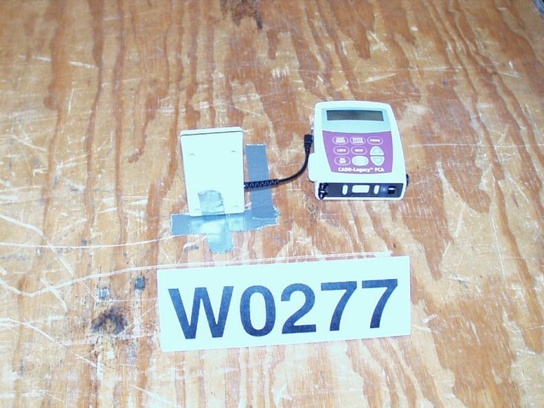
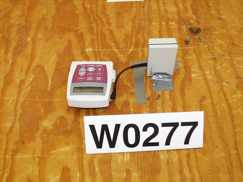
TEST SETUP FOR EMISSIONS TESTING WILD RIVER LAB Small Test Site (STS) EUT 180 27090 0 60 Hz 50 Hz Turntable is 1.2 meters in diameter Enlarged View of Shelter (4 meters square) STS Building Shelter 3 meter antenna 10 meter antenna 30 meter antenna Turntable Control Cable Ground Screen (34 meters long x 12 meters wide) 8 meters
Contact Information
Applicant
Ronald A Dohmen(Sr Engineer)
Test Firm
TUV SUD America - Product ServiceJoel Schneider
Technical Specifications
| # | Rule Parts | Frequency Range | Power Output |
|---|---|---|---|
| 1 | 15.231(e) | 418 MHz - 418 MHz | - |
Other Applications from SIMS Deltec, Inc.

OSK6330-51
Feb 24, 2000DSC - Part 15 Security/Remote Control Transmitter
Equipment Class
DSC - Part 15 Security/Remote Control Transmitter