OTA28692CRC-XD VIDEO SURVEILLANCE VEHICLE
Jakks Pacific (HK) Ltd.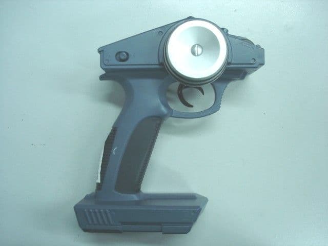
Click to zoom
Application Details
- Equipment Class
- DXT - Part 15 Low Power Transceiver, Rx Verified
- Date of Grant
- Aug 26, 2010
- Application Purpose
- Original Equipment
- Date of Application
- Aug 24, 2010
- Equipment Note
- RC-XD VIDEO SURVEILLANCE VEHICLE
- Frequency Range
- 2410.87500000 - 2464.87500000
- Company
- Jakks Pacific (HK) Ltd.
- Country
- Hong Kong
Documents & Files
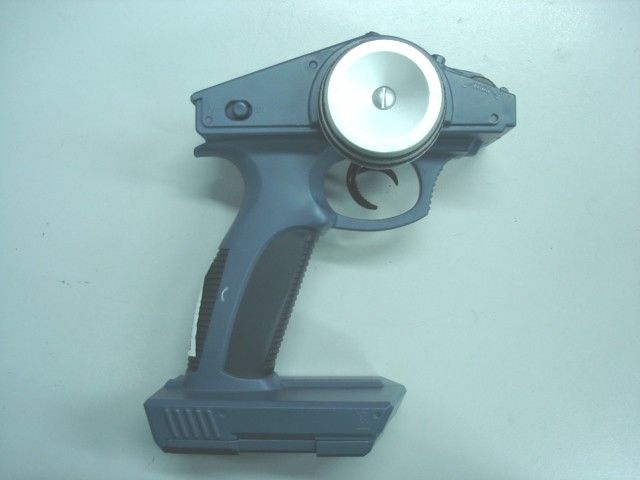
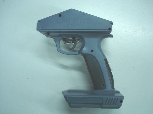
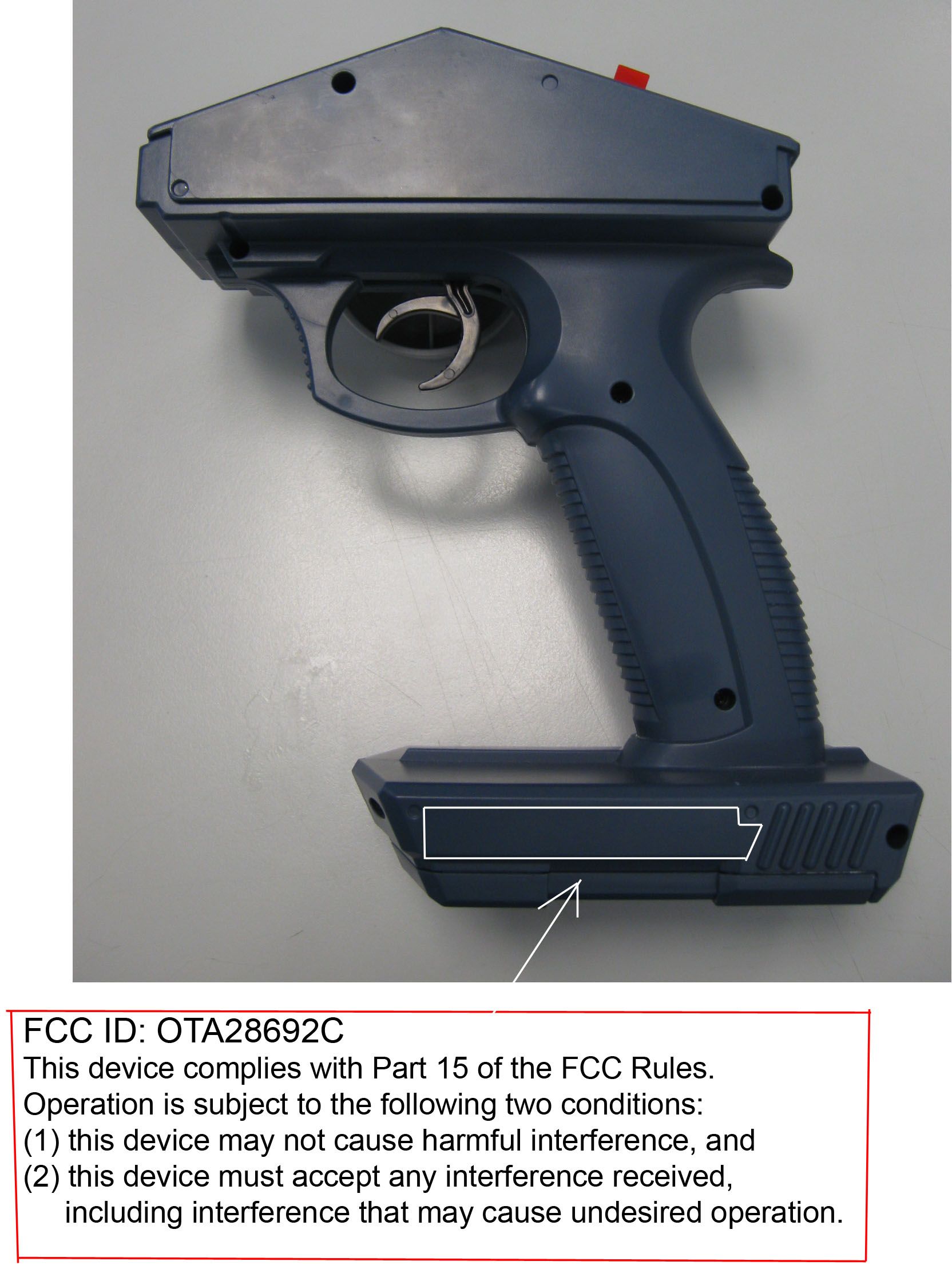
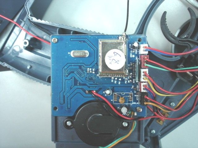
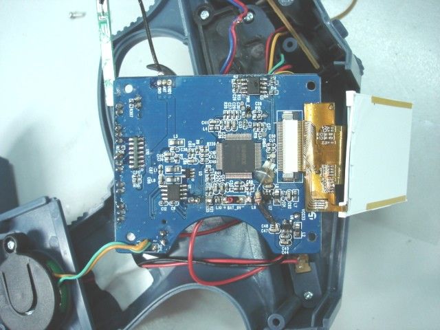
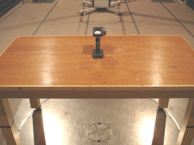
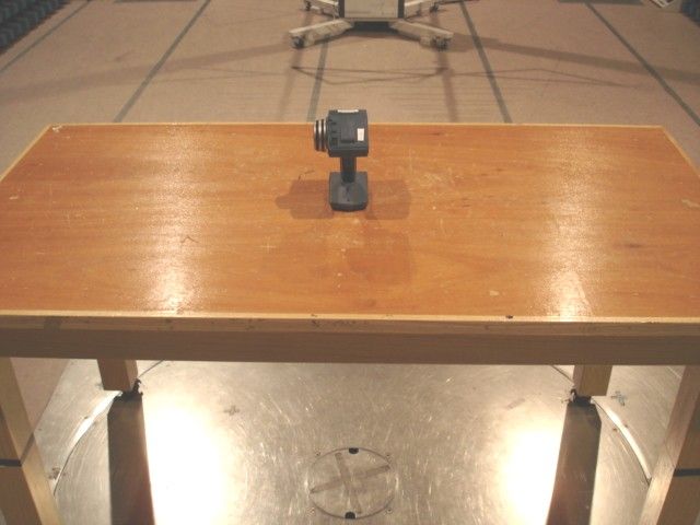
Document Text
Text extracted from the exhibit documents filed with the FCC. Open a document above to read the original.
Users Manual
32 1.5V “AA”, LR6 - + 1.5V “AA”, LR61.5V “AA”, LR61.5V “AA”, LR6 - + 1.5V “AA”, LR61.5V “AA”, LR6 - + - + - + - + 1.5V “AA”, LR6 - + 1.5V “AA”, LR6 - + 1.5V “AA”, LR6 - + 1.5V “AA”, LR6 - + 1.5V “AA”, LR6 - + + 1.5V “AA”, LR6 - VEHICLE BATTERY INSTALLATION Requires 6 AA (LR6) alkaline batteries Requires 6 AA (LR6) alkaline batteries TRANSMITTER INSTRUCTIONS STEERING TRIM VOLUME / DISPLAY SPEED / PAIRING LCD SCREEN ON/OFF STEERING WHEEL (LEFT / RIGHT) Press button to adjust 0-4 level (0 = no sound). Push and hold the volume key for 3 seconds to power on/off the display. Press button to adjust HIGH or LOW Speed Mode. Default setting is LOW. THROTTLE TRIGGER (FORWARD / REVERSE) LED SPEAKER LCD SCREEN TRANSMITTER RC-XD VIDEO SURVEILLANCE VEHICLE CAUTION TROUBLESHOOTING Indicates volume level 0-4 Antenna signal strength VEHICLE OPERATION microphone lens LED ON/OFF 1. Never steer into other objects. Impact may damage vehicle. 2. Never drive through water or mud as vehicle is not waterproof. 3. Never drive vehicle in parking lots, near roads, pets or cars. 4. Never touch the rear wheels or pick up the vehicle while it is in motion. 5. Always keep fingers, hair, and eyes away from the wheels while the vehicle is in the “ON” position. 6. Always store vehicle in a cool, dry place. Never store near heat or direct sunlight. Recommended for video monitor usage. Recommended for approaching targets. LOW SPEED MODE HIGH SPEED MODE Battery Icons (V for Vehicle / T for Transmitter) - the icons will display in Red color when battery is low. H or L appears for 3 seconds when the Speed button is pressed to switch between HIGH and LOW Speed Mode. 1. Turn on the power for both the vehicle and the transmitter. 2. Test the transmitter and vehicle by turning the transmitter steering wheel and watching to see if the vehicle's wheels turn as well. If not, see PAIRING information in troubleshooting section below. 3. Apply gentle pressure to the throttle by pulling the trigger back to move the vehicle forward. Apply more pressure to the throttle to increase speed. Slow or reverse the vehicle by reversing the direction of pressure on the throttle trigger. The default speed setting is LOW. NOTE: If the vehicle does not drive straight when no steering input is given, adjust the front wheel angle using the steering trim. 4. Steer the vehicle by turning the steering wheel on the transmitter in the direction you wish the vehicle to go. Slight changes to the wheel will result in gentle turns, while sharp twists of the steering will result in sharp turns. Push and hold the volume key for 3 seconds to power on/off the display. In HIGH Speed mode, it is recommended to turn LCD screen off. T V ❚ PAIRING - Press and hold the Speed/Pairing button until the LED flashes on the transmitter. Then, using a small point (such as a paper clip), press the Pairing button on the bottom of the vehicle to complete the pairing process. The pairing information will be stored in the vehicle's memory automatically and will remain even after it is turned off. ❚ If the vehicle will not operate or slows down, or the video screen starts to fade, batteries may need to be replaced. ❚ If the vehicle is not traveling in a straight line, adjust the front wheel alignment using the steering trim. ❚ If the vehicle moves erratically without the transmitter, or the LCD screen begins to flicker, there may be interference with the signal, the vehicle is out of range, or the batteries are running low. To fix this, try: 1) moving to a new location, 2) holding the transmitter higher above the ground, 3) moving closer to the vehicle, or 4) replacing the batteries. ❚ Direct sunlight into the vehicle’s camera may cause the transmitter’s LCD screen to turn white. Move the camera’s angle away from the sun to restore the LCD screen. ❚ If the LCD screen is flickering a lot, move to a new location. PAIRING BUTTON Place car on stand as shown. Front CoverBack Cover InsideInside Item No.: Description: Color(s): Dimension (Width x Height x Depth): Primary Display Panel (PDP) Size: Product Line: Studio: Customer: Vendor: Activision RC Car In-house Rumble Car - Instruction 11”(W) x 8.5”(H) - with one folding 13”(W) x 22”(H) 28692/29431 Version: US Early Light Revision: 01 Minimum Packaging Spec.:- Coating: xBlack ONLY 12 AA’s Required (Not Included) Ages 8+ RC-XD VIDEO SURVEILLANCE VEHICLE MANUAL COLLECTOR STAND ASSEMBLY IMPORTANT SAFETY INFORMATION / BATTERY WARNINGS AND PROPER USE Locate battery compartments on bottom of vehicle and transmitter. Using a Phillips screwdriver, remove the screws and battery door. Install batteries. Replace the battery cover and the screws. For better performance, high capacity rechargeable nickel-metal hydride (NiMH) batteries are recommended. This device complies with Part 15 of the FCC Rules. Operation is subject to the following two conditions : (1) this device may not cause harmful interference, and (2) this device must accept any interference received, including interference that may cause undesired operation. Warning: Changes or modifications to this unit not expressly approved by the party responsible for complianace could void the user’s authority to operate the equipment. This equipment has been tested and found to comply with the limits for a Class B digital device, pursuant to Part 15 of the FCC Rules. These limits are designed to provide reasonable protection against harmful interference in a residential installation. This equipment generates, uses, and can radiate radio frequency energy and, if not installed and used in accordance with the instructions, may cause harmful interference to radio communications. However, there is no guarantee that interference will not occur in a particular installation. If this equipment does cause harmful interference to radio or television reception, which can be determined by turning the equipment off and on, the user is encouraged to try to correct the interference by one or more of the following me…
Text truncated - open the document above for the full version.
Test Report
TEST REPORT Report No. : AM0039647(7) Date : 2010-08-18 Page 1 of 13 FCC ID: OTA28692C This document is issued subject to CMA Testing standard TEARMS AND CONDITIONS, and shall not be reproduced except in full or with written approval by CMA Testing. CMA Industrial Development Foundation Limited Room 1302, Yan Hing Centre, 9-13 Wong Chuk Yeung St.., Fo Tan, Shatin, Hong Kong. Tel: (852) 2698 8198 Fax: (852) 2695 4177 E-mail: [email protected] Web Site: http://www.cmatcl.com Application No. : LM011838(0) Applicant : Jakks Pacific (H.K.) Ltd 12/F, Wharf T&T Centre, 7 Canton Road, Tsim Sha Tsui, Hong Kong Sample Description : One(1) submitted sample(s) stated to be RC-XD Video Surveillance Vehicle of Model No. #28692 and #29431 Radio Frequency : 2410.875MHz ~ 2464.875MHz Transceiver Rating : 6 x 1.5V AA size batteries No. of submitted sample : Three (3) piece(s) Date Received : 2010-07-23. Test Period : 2010-07-23 to 2010-08-05. Test Requested : FCC Part 15 Certification. Test Method : 47 CFR Part 15 (10-1-09 Edition) ANSI C63.4 – 2003 Test Result : See attached sheet(s) from page 2 to 13. Conclusion : The submitted sample was found to comply with requirement of FCC Part 15 Subpart B and C. Remark : All two models are the same in circuitry, component and construction. Therefore, model #28692 was chosen to be the representative of the test sample. For and on behalf of CMA Industrial Development Foundation Limited Authorized Signature : ____________________________________________________ Mr. Wong Lap-pong, Andrew Assistant Manager Electrical Division TEST REPORT Report No. : AM0039647(7) Date : 2010-08-18 Page 2 of 13 FCC ID: OTA28692C This document is issued subject to CMA Testing standard TEARMS AND CONDITIONS, and shall not be reproduced except in full or with written approval by CMA Testing. CMA Industrial Development Foundation Limited Room 1302, Yan Hing Centre, 9-13 Wong Chuk Yeung St.., Fo Tan, Shatin, Hong Kong. Tel: (852) 2698 8198 Fax: (852) 2695 4177 E-mail: [email protected] Web Site: http://www.cmatcl.com Table of Contents 1 General Information............................................................................................................................. 3 1.1 General Description ..................................................................................................................... 3 1.2 Location of the test site................................................................................................................ 4 1.3 List of measuring equipment ....................................................................................................... 5 1.4 Measurement Uncertainty............................................................................................................ 5 2 Description of the radiated emission test............................................................................................. 6 2.1 Test Procedure ............................................................................................................................. 6 2.2 Test Result ................................................................................................................................... 6 2.3 Radiated Emission Measurement Data ........................................................................................ 7 2.3 Radiated Emission Measurement Data (Con’t) ........................................................................... 8 2.3 Radiated Emission Measurement Data (Con’t) ........................................................................... 9 3 Description of the Line-conducted Test ............................................................................................ 10 3.1 Test Procedure ........................................................................................................................... 10 3.2 Test Result ................................................................................................................................. 10 3.3 Graph and Table of Conducted Emission Measurement Data .................................................. 10 4 Photograph ......................................................................................................................................... 11 4.1 Photographs of the Test Setup for Radiated Emission and Conducted Emission ..................... 11 4.2 Photographs of the External and Internal Configurations of the EUT ...................................... 11 5 Supplementary document .................................................................................................................. 12 5.1 Band edges ................................................................................................................................. 12 5.2 Duty cycle .................................................................................................................................. 12 5.3 Transmission time...................................................................................................................... 12 6 Appendices ........................................................................................................................................ 13 TEST REPORT Report No. : AM0039647(7) Date : 2010-08-18 Page 3 of 13 FCC ID: OTA28692C This document is issued subject to CMA Testing standard TEARMS AND CONDITIONS, and shall not be reproduced except in full or with written approval by CMA Testing. CMA Industrial Development Foundation Limited Room 1302, Yan Hing Centre, 9-13 Wong Chuk Yeung St.., Fo Tan, Shatin, Hong Kong. Tel: (852) 2698 8198 Fax: (852) 2695 4177 E-mail: [email protected] Web Site: http://www.cmatcl.com 1 General Information 1.1 General Description The equipment under test (EUT) is a transceiver for RC-XD Video Surveillance Vehicle. It operates at 2410.875MHz ~ 2464.875MHz and the oscillation of MCU is generated by a crystal. The EUT is powered by 6 x 1.5V AA size batteries. Th…
Text truncated - open the document above for the full version.
Test Report
Workform Job No. Document Ref No: WF-EL-EMC-15 Page of Issue Date: 2010-01-11 Edition: 1 (Amd 2) Band Edges Plot Band Edge 1 (2.4GHz Edge with Peak Detector) Band Edge 2 (2.4GHz Edge with Average Detector) Workform Job No. Document Ref No: WF-EL-EMC-15 Page of Issue Date: 2010-01-11 Edition: 1 (Amd 2) Band Edges Plot Band Edge 3 (2.4835GHz Edge with Peak Detector) Band Edge 4 (2.4835GHz Edge with Average Detector)
Test Report
Workform Job No. Document Ref No: WF-EL-EMC-15 Page of Issue Date: 2010-01-11 Edition: 1 (Amd 2) Duty Cycle Duty Cycle 1 (First Channel) Duty Cycle 2 (Middle Channel) Workform Job No. Document Ref No: WF-EL-EMC-15 Page of Issue Date: 2010-01-11 Edition: 1 (Amd 2) Duty Cycle Duty Cycle 3 (Last Channel)
Contact Information
Applicant
Dick Au(Senior Manager , Product Integrity)
Test Firm
CMA Industrial Development Foundations LimitedAndrew Wong
Technical Specifications
| # | Rule Parts | Frequency Range | Power Output |
|---|---|---|---|
| 1 | 15C | 2.41 GHz - 2.46 GHz | - |
Other Applications from Jakks Pacific (HK) Ltd.
OTA78969TXNT
Mar 24, 2024Mario Kart Mini Motorcycle RC Racer
Equipment Class
DXX - Part 15 Low Power Communication Device TransmitterOTA78969RXNT
Mar 24, 2024Mario Kart Mini Motorcycle RC Racer
Equipment Class
DXX - Part 15 Low Power Communication Device Transmitter
OTA41822RX
Jan 05, 2023Super Mario Rumble RCC
Equipment Class
DXX - Part 15 Low Power Communication Device Transmitter
OTA41822TX
Dec 29, 2022Super Mario Rumble RC
Equipment Class
DXX - Part 15 Low Power Communication Device Transmitter
OTA71207RX
Aug 25, 2021RNR Lightning Luna-AA
Equipment Class
DXX - Part 15 Low Power Communication Device Transmitter