OTARC73630T4949 MHz Transmitter
Jakks Pacific (HK) Ltd.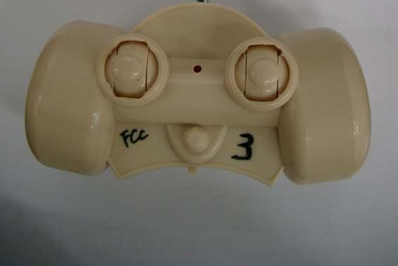
Click to zoom
Application Details
- Equipment Class
- DXX - Part 15 Low Power Communication Device Transmitter
- Date of Grant
- Nov 04, 2005
- Application Purpose
- Original Equipment
- Date of Application
- Nov 04, 2005
- Equipment Note
- 49 MHz Transmitter
- Frequency Range
- 49.86000000 - 49.86000000
- Company
- Jakks Pacific (HK) Ltd.
- Country
- Hong Kong
Documents & Files
Document Text
Text extracted from the exhibit documents filed with the FCC. Open a document above to read the original.
Cover Letter(s)
American Telecommunications Certification Body Inc. 6731 Whittier Ave, McLean, VA 22101 November 3, 2005 RE: Jakks Pacific (HK) Ltd. FCC ID: OTARC73630T49 After a review of the submitted information, I have a few comments on the above referenced Application. 1) Please confirm that confidentiality is not required or requested on any exhibits. 2) The FCC ID shown on the FCC labeling exhibits appears incorrect. Please review and correct. 3) The test report supports compliance to Part 15, however Part 15 specifies the limits and requirements. Test methods should follow ANSI C63.4-2003. Please ensure the device has been tested with this standard and update the report as necessary. 4) ANSI C63.4 specifies that a portable device must be tested while positioned in each of 3 axis in effort to obtain worse case results. The report photos and the report page 7 suggests maybe only 2 positions were tested. Please review and correct as necessary. 5) For field strength measurements > 30 MHz, a RBW > 100 kHz (typically 120 kHz EMC bandwidth is used) must be used. Measurements suggest a 9 kHz RBW was used (page 8 of the report). 6) Please confirm RBW used for spurious field strength measurements made > 30 MHz. 7) It is uncertain if the Antenna Factors are figured into the calculations or measurements made. Because of the low results obtained, we are trying to confirm that the measurements were properly adjusted for Antenna factors, cable loss, and amplifiers. Please confirm. 8) FYI (For Your Information)....Peak measurements appear to meet Average limits. However if the peak measurements had exceeded the average limits, further information regarding the modulation may have been necessary. For instance is the carrier pulsed in nature? If so, then average measurements are actually not a measurement, but simply the peak measurements corrected for worse case duty factor (following 15.35(c) of the rules). Note that most of these types of devices do actually contain pulsed emissions. Timothy R. Johnson Examining Engineer mailto: [email protected] The items indicated above must be submitted before processing can continue on the above referenced application. Failure to provide the requested information may result in application termination. Correspondence should be considered part of the permanent submission and may be viewed from the Internet after a Grant of Equipment Authorization is issued. Please do not respond to this correspondence using the email reply button. In order for your response to be processed expeditiously, you must submit your documents through the AmericanTCB.com website. Also, please note that partial responses increase processing time and should not be submitted. Any questions about the content of this correspondence should be directed to the sender.
Cover Letter(s)
Dear Tim, 1) It is confirmed by the client on telephone that confidentiality is not required or requested on any exhibits. 2) A new labeling exhibit has been prepared to replace the old ones. Only the label and its location for the device to be certified is included. 3) The test report does mention the ANSI C63.4-2003 as the test standard on page 2. The device has been tested with this standard. 4) The requirement to position portable device in 3 orthogonal axis during exploratory test is mentioned at the bottom of page 6 of the test report. The positions mentioned on page 7 are only the initial configuration at the start of the test. 5) For field strength measurement above 30MHz, we did apply RBW of 120kHz to get the final measurement results. The test report will be corrected accordingly. 6) Since Quasi-Peak Detector of the R&S ESCS30 Test Receiver is employed in measuring the spuious emissions (see page 7 of the report), the RBW is autoamtically configured to 120kHz, Anyway, we will amend the test report to have it stated explicitly in the remark on page 7. 7) I confirm here that the Antenna Factors, the cable loss and all the correction factors have been figured into the calculations or measurements made; otherwise, the unit of field strength dBuV/m cannot be displayed on the user interactive interface of both the test software and the test equipment. 8) FYI : I did asked the client for information. He replied me that the modulation is AM. But I am not sure whether the client himself have the clear idea or not, because it is embeded in the chipset provided by the IC manufacturer. Yours sincerely, WAI Leong EMC Engineer Bureau Veritas Hong Kong Ltd.
External Photos
Technical Report: (5205) 298-0212 Date: 31 October 2005 Page 1 of 2 Photographs: EUT Exterior Sample Description: Fly Wheels R/C Skate Radio Remote Control Transmitter (49.860 MHz) FCC ID (if applicable): OTARC73630T49 Photo No. 1 : The front view Technical Report: (5205) 298-0212 Date: 31 October 2005 Page 2 of 2 Photographs: EUT Exterior Sample Description: Fly Wheels R/C Skate Radio Remote Control Transmitter (49.860 MHz) FCC ID (if applicable): OTARC73630T49 Photo No. 1 : The back view
ID Label/Location Info
JAKKS PACIFIC (HK) LTD. Technical Report: (5205)298-0212 Nov. 4, 2005 LABEL Sample Description: FLY WHEELS R/C SKATE RF Remote Controller (49.86 MHz) FCC ID (if applicable): OTARC73630T49 A): Label: JAKKS PACIFIC (HK) LTD. Technical Report: (5205)298-0212 Nov. 4, 2005 B) Location: C) Location: - Marking of Country of Origin:
Internal Photos
Technical Report: (5205) 298-0212 Date: 31 October 2005 Page 1 of 2 Photographs: EUT Interior Sample Description: Fly Wheels R/C Skate Radio Remote Control Transmitter (49.860 MHz) FCC ID (if applicable): OTARC73630T49 Photo No. 1 : PCB Solder Side Technical Report: (5205) 298-0212 Date: 31 October 2005 Page 2 of 2 Photographs: EUT Interior Sample Description: Fly Wheels R/C Skate Radio Remote Control Transmitter (49.860 MHz) FCC ID (if applicable): OTARC73630T49 Photo No. 2 : PCB Component Side
Operational Description
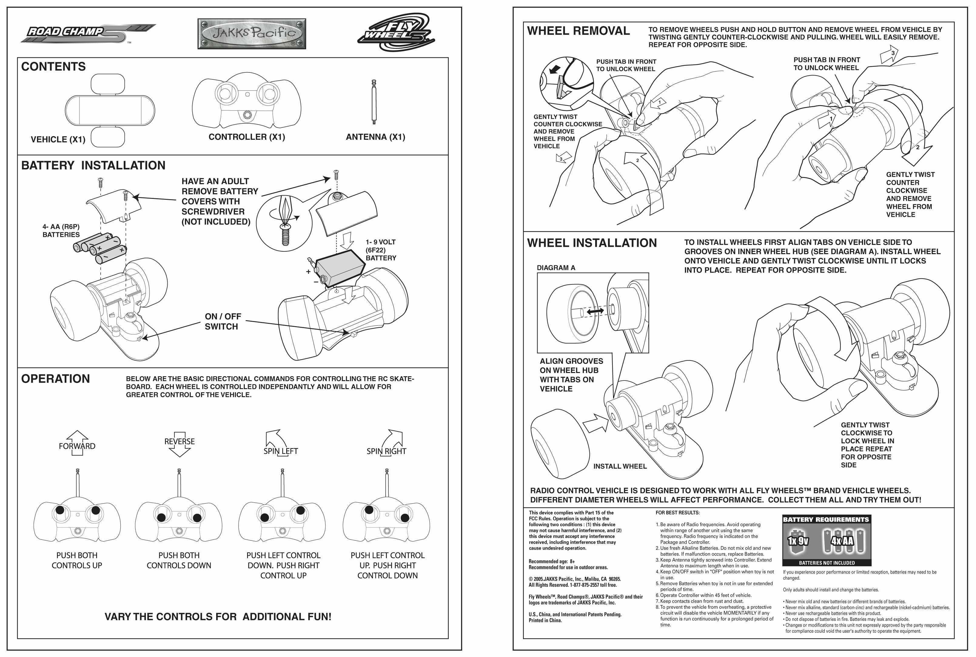
Description of EUT Operation : SAMPLE DESCRIPTION: FLY WHEELS R/C SKATE RF Remote Controller (49.86 MHz) APPLICANT: Jakks Pacific (HK) Ltd FCC ID: OTARC73630T49 Circuit Description: Q1 the 49.86 MHz crystal oscillator drives the base of Q2 the final/ buffer amplifier. Summed into the same base (Q2) is the modulation provided by IC1. The output of Q2 has the matching network consisting of T1, L3, L2, C10, C11, and C12 that limit the harmonic content and effect the proper coupling of the antenna to the output stage. Antenna, Ground, and Power Source The antenna consists of a 48 cm long telescoping chrome over brass tubing. There is no external ground connection. The ground is only that of the printed circuit board. Electric current is supplied by 1pcs 9Volt primary storage cell.
Test Setup Photos
Technical Report: (5205) 298-0212 Date: 31 October 2005 Page 1 of 2 Photographs: Test Setup Sample Description: Fly Wheels R/C Skate Radio Remote Control Transmitter (49.860 MHz) FCC ID (if applicable): OTARC73630T49 Photo No. 1 : Test Setup Of Vertical Polarization Technical Report: (5205) 298-0212 Date: 31 October 2005 Page 2 of 2 Sample Description: Fly Wheels R/C Skate Radio Remote Control Transmitter (49.860 MHz) FCC ID (if applicable): OTARC73630T49 Photo No. 1 : Test Setup Of Horizontal Polarization
Contact Information
Applicant
Dick Au(Senior Manager , Product Integrity)
Technical Contact
Bureau Vertitas Hong Honk Ltd.L Wait
1/F, Pacific Trade Center, 2 Kai · Kowloon · Hong Kong
Test Firm
Bureau Veritas Consumer Products Services (H.K.)Kent Lai
Technical Specifications
| # | Rule Parts | Frequency Range | Power Output |
|---|---|---|---|
| 1 | 15C | 49.86 MHz - 49.86 MHz | - |
Other Applications from Jakks Pacific (HK) Ltd.
OTA78969TXNT
Mar 24, 2024Mario Kart Mini Motorcycle RC Racer
Equipment Class
DXX - Part 15 Low Power Communication Device TransmitterOTA78969RXNT
Mar 24, 2024Mario Kart Mini Motorcycle RC Racer
Equipment Class
DXX - Part 15 Low Power Communication Device Transmitter
OTA41822RX
Jan 05, 2023Super Mario Rumble RCC
Equipment Class
DXX - Part 15 Low Power Communication Device Transmitter
OTA41822TX
Dec 29, 2022Super Mario Rumble RC
Equipment Class
DXX - Part 15 Low Power Communication Device Transmitter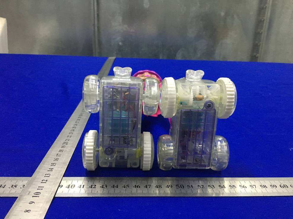
OTA71207RX
Aug 25, 2021RNR Lightning Luna-AA
Equipment Class
DXX - Part 15 Low Power Communication Device Transmitter