OTARC74115R49Mini RAD
Jakks Pacific (HK) Ltd.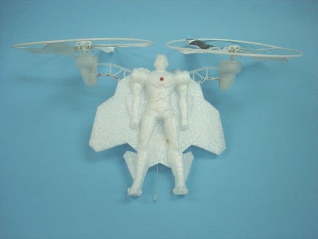
Click to zoom
Application Details
- Equipment Class
- CRR - Superregenerative Receiver
- Date of Grant
- Jul 04, 2007
- Application Purpose
- Original Equipment
- Date of Application
- Jul 04, 2007
- Equipment Note
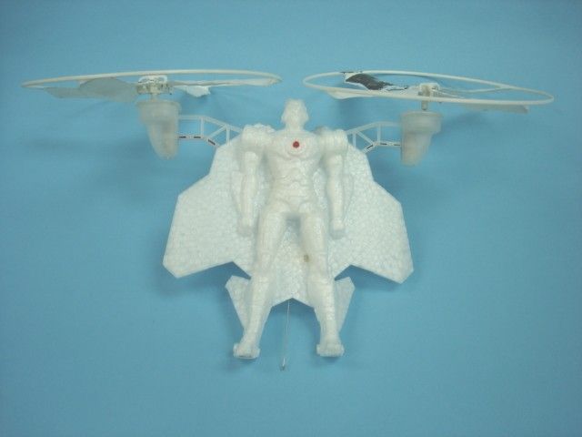
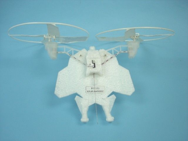
- Mini RAD
- Frequency Range
- 49.86000000 - 49.86000000
- Company
- Jakks Pacific (HK) Ltd.
- Country
- Hong Kong
Documents & Files
Document Text
Text extracted from the exhibit documents filed with the FCC. Open a document above to read the original.
Block Diagram
PDF created with pdfFactory Pro trial version www.pdffactory.com
Operational Description
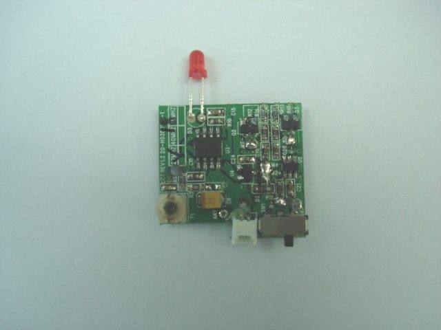
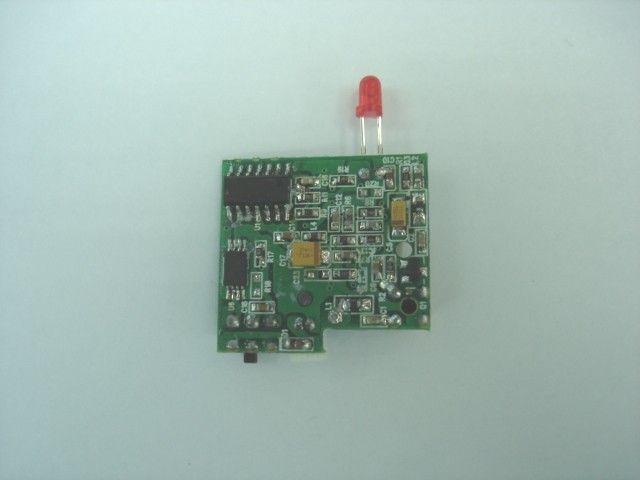
XPV MINI RAD 49.860MHz receiver operational description of mini plane The mini RAD is a full function radio controlled toy RAD .It is 3.7 volts rechargeable Li-Po pack battery .This RAD is designed to operate on a signal fixed frequency in 49.82~49.90MHz .Please consult with added block diagram and schematic . The modulated RF signal from the transmitter coupling to U1, then VR(forward), R(right),L(left) and tiny key(tact key) signal will be decoded by L1,T1 and Q1 makes up of oscillator ,which sends out basic oscillatory signal to U3 . The signal of F ,L and R from transmitter is processed by U1 . the order signal of F,L and R will be generated in the form of an electronic signal and then enter into drive circuit .When the forward electronic signal enter into Q2,Q3. Here the motor 1 and motor 2 will be controlled run. When the L, R or tiny electronic signal enter into Q2, Q3. Here the Motor 1 and motor 2 will be controlled run on the one low and other one high speed. U2 is Li-Po battery protect IC. When RX will charge about battery .it need join that TX jack. RX Charge finish(battery is 4.3V) that the U2 1 pin will to low volts.When battery volts is to low(2.5 or down) that the U2 3 pin will to low volts. Then RX will stop work. LED is act as a power-on indicator. All tuning and verifications are performed by the manufacturer and there are no adjustments which can be made by the user . No external ground is required or used with this receiver .
Schematics
1234 A B C D 4321 D C B A Title NumberRevisionSize A4 Date:15-Jun-2007Sheet of File:D:\data\JAKKS\H038\SCH\EP H038.Ddb做板用线路原理图Drawn By: ANT L1 2.2UH C1 5PF Q1 2SC2712Y C2 12PF L2 3.3UH R1 1K C3 2200PF R2 100K C5 4.7UF C4 2PF C6 0.01UF R3 6.8K C7 1000PF C8 100UF R4 2.2K R5 100K 2 3 1 - + U3-A LM358 R7 180K L3 100nH C10 0.1UF R6 4.7K C12 0.22UF R8 180K C13 100PF R10 82K C15 0.22UF R94.7K C16 1000PF C17 100UF 1 2 3 4 5 6 78 9 10 11 12 13 14 U1SN8P2501 C9 0.01UF M1M2 C19 2.2UF C20 2.2UF Q2 AP2306 Q3 AP2306 R13 10K R15 10K R14 1K R12 1K 123 456 U2 FS326 Q4 AO8810 R16 100R C21 0.1UF R17 1K BATT 3.7V 90mA CH+ CH- 6 5 7 - + U3-B LM358 SW1 C18 0.1UF D1 1N5819 T1 0.66UH 1 23 U4 XC6206 3.0V L4 100nH C14 0.1UF D2 1N5819 R11 1K R19 1K LED 8 4 U3 C24 0.01UF C11 1UF P2.2 P2.1 P2.0 VDD P1.3/XIN P1.2/XOUT P1.1/RST/VPP P5.4/BZO/PWM0 P1.0 P0.0/INT0 VSS P2.5 P2.4 P2.3 L R 49.860MHZ PDF created with pdfFactory Pro trial version www.pdffactory.com
Test Report
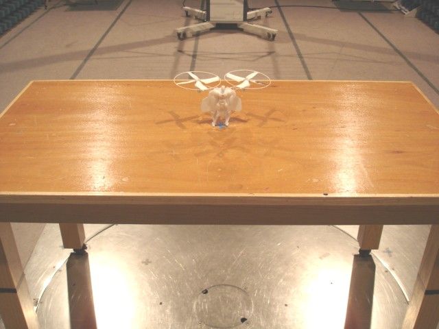
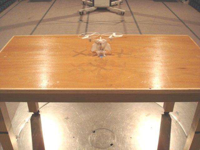
TEST REPORT Report No. : AJ014861-001 Date : 2007 July 04 Page 1 of 11 FCC ID: OTARC74115R49 This document shall not be reproduced except in full or with written approval by the laboratory. CMA Industrial Development Foundation Limited Room 1302, Yan Hing Centre, 9-13 Wong Chuk Yeung St.., Fo Tan, Shatin, Hong Kong. Tel: (852) 2698 8198 Fax: (852) 2695 4177 E-mail: [email protected] Web Site: http://www.cmatcl.com Application No. : LJ212114(0) Client : Jakks Pacific (HK) Ltd 12/F, Wharf T&T Centre, 7 Canton Road, Tsim Sha Tsui, Hong Kong Sample Description : One(1) submitted sample(s) stated to be Mini RAD of Model No. 74115 Radio Frequency : 49.860MHz Receiver Rating : 1 x 3.7V rechargeable No. of submitted sample : Two (2) piece(s) *** Date Received : 2007 June 01 Test Period : 2007 June 12 ñ 2007 June 15 Test Requested : FCC Part 15 Certification. Test Method : 47 CFR Part 15 (10-1-05 Edition) ANSI C63.4 ñ 2003 Test Result : See attached sheet(s) from page 2 to 11. Conclusion : The submitted sample was found to comply with requirement of FCC Part 15 Subpart B. For and on behalf of CMA Industrial Development Foundation Limited Authorized Signature : ____________________________________________________ Danny Chui Deputy Manager - EL. Division TEST REPORT Report No. : AJ014861-001 Date : 2007 July 04 Page 2 of 11 FCC ID: OTARC74115R49 This document shall not be reproduced except in full or with written approval by the laboratory. CMA Industrial Development Foundation Limited Room 1302, Yan Hing Centre, 9-13 Wong Chuk Yeung St.., Fo Tan, Shatin, Hong Kong. Tel: (852) 2698 8198 Fax: (852) 2695 4177 E-mail: [email protected] Web Site: http://www.cmatcl.com Table of Contents 1 General Information .............................................................................................................................3 1.1 General Description .....................................................................................................................3 1.2 Location of the test site ................................................................................................................4 1.3 List of measuring equipment........................................................................................................5 2 Description of the radiated emission test .............................................................................................6 2.1 Test Procedure..............................................................................................................................6 2.2 Test Result....................................................................................................................................6 3 Description of the Line-conducted Test...............................................................................................8 3.1 Test Procedure..............................................................................................................................8 3.2 Test Result....................................................................................................................................8 3.3 Graph and Table of Conducted Emission Measurement Data .....................................................8 4 Photograph ...........................................................................................................................................9 4.1 Photographs of the Test Setup for Radiated Emission and Conduction Emission ......................9 4.2 Photographs of the External and Internal Configurations of the EUT.........................................9 5 Supplementary document ...................................................................................................................10 5.1 Bandwidth ..................................................................................................................................10 5.2 Duty cycle ..................................................................................................................................10 5.3 Transmission time ......................................................................................................................10 5.4 Power Spectral Density ..............................................................................................................10 6 Appendices .........................................................................................................................................11 TEST REPORT Report No. : AJ014861-001 Date : 2007 July 04 Page 3 of 11 FCC ID: OTARC74115R49 This document shall not be reproduced except in full or with written approval by the laboratory. CMA Industrial Development Foundation Limited Room 1302, Yan Hing Centre, 9-13 Wong Chuk Yeung St.., Fo Tan, Shatin, Hong Kong. Tel: (852) 2698 8198 Fax: (852) 2695 4177 E-mail: [email protected] Web Site: http://www.cmatcl.com 1 General Information 1.1 General Description The equipment under test (EUT) is a receiver for Mini RAD. It operates at 49.860MHz and the oscillation of radio control is generated by a LRC circuit. The EUT is powered by 1x 3.7V rechargeable battery. When it received an accelerated, turn right or turn left signal, it will accelerate or move to the corresponding direction. The brief circuit description is listed as follows: - T1, Q1 and associated circuit act as a RF amplifier. - U3-A, U3-B and associated circuit act as a signal amplifier. - U4 and associated circuit act as a voltage regulator. - U1 and associated circuit act as a decoder. - Q2 and associated circuit act as a motor driver for M1. - Q3 and associated circuit act as a motor driver for M2. - U2, Q4 and associated circuit act as a charging circuit. TEST REPORT Report No. : AJ014861-001 Date : 2007 July 04 Page 4 of 11 FCC ID: OTARC74115R49 This document shall not be reproduced except in full or with written approval by the laboratory. CMA Industrial Development Foundation Limited Room 1302, Yan Hing Centre, 9-13 …
Text truncated - open the document above for the full version.
Contact Information
Applicant
Dick Au(Senior Manager , Product Integrity)
Test Firm
CMA Industrial Development Foundations LimitedStephen Lam
Technical Specifications
| # | Rule Parts | Frequency Range | Power Output |
|---|---|---|---|
| 1 | 15B | 49.86 MHz - 49.86 MHz | - |
Other Applications from Jakks Pacific (HK) Ltd.
OTA78969TXNT
Mar 24, 2024Mario Kart Mini Motorcycle RC Racer
Equipment Class
DXX - Part 15 Low Power Communication Device TransmitterOTA78969RXNT
Mar 24, 2024Mario Kart Mini Motorcycle RC Racer
Equipment Class
DXX - Part 15 Low Power Communication Device Transmitter
OTA41822RX
Jan 05, 2023Super Mario Rumble RCC
Equipment Class
DXX - Part 15 Low Power Communication Device Transmitter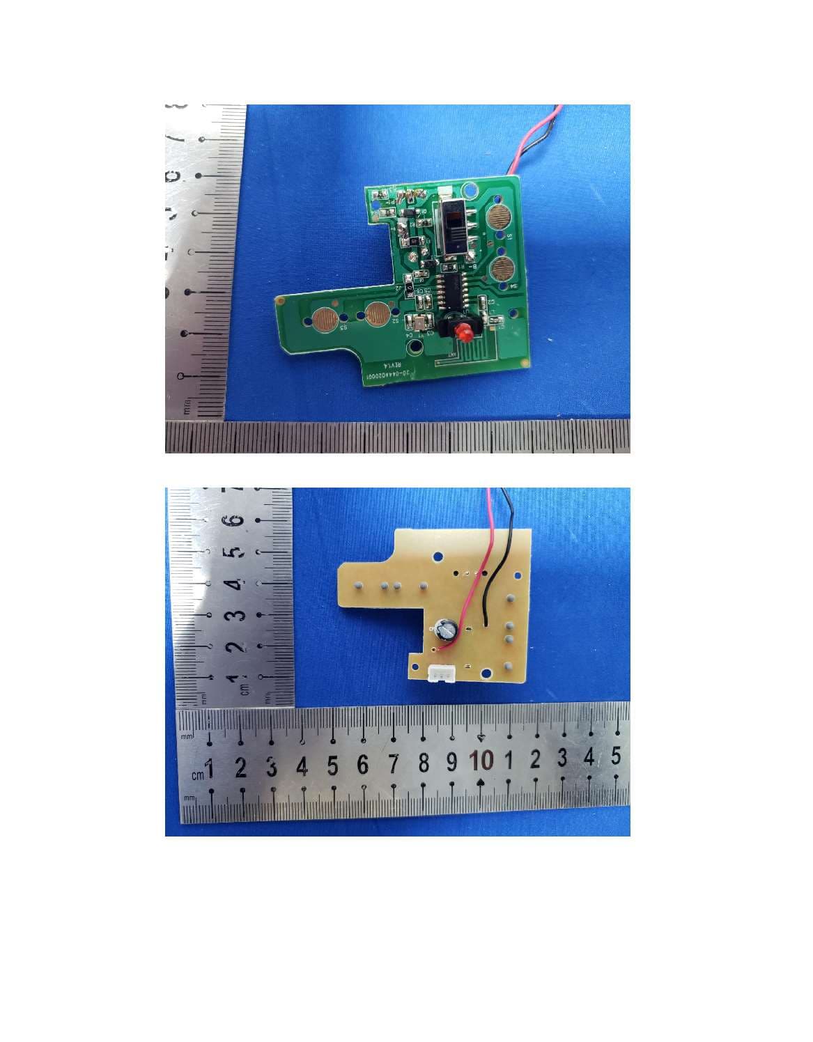
OTA41822TX
Dec 29, 2022Super Mario Rumble RC
Equipment Class
DXX - Part 15 Low Power Communication Device Transmitter
OTA71207RX
Aug 25, 2021RNR Lightning Luna-AA
Equipment Class
DXX - Part 15 Low Power Communication Device Transmitter