OTC-PD0001Packaged Goods Inspection System
Prism Systems Inc.
Click to zoom
Application Details
- Equipment Class
- FDS - Part 15 Field Disturbance Sensor
- Date of Grant
- Feb 24, 2000
- Application Purpose
- Original Equipment
- Date of Application
- Feb 10, 2000
- Equipment Note
- Packaged Goods Inspection System
- Frequency Range
- 10533.00000000 - 10533.00000000
- Company
- Prism Systems Inc.
- Country
- United States
Documents & Files
Document Text
Text extracted from the exhibit documents filed with the FCC. Open a document above to read the original.
ID Label/Location Info
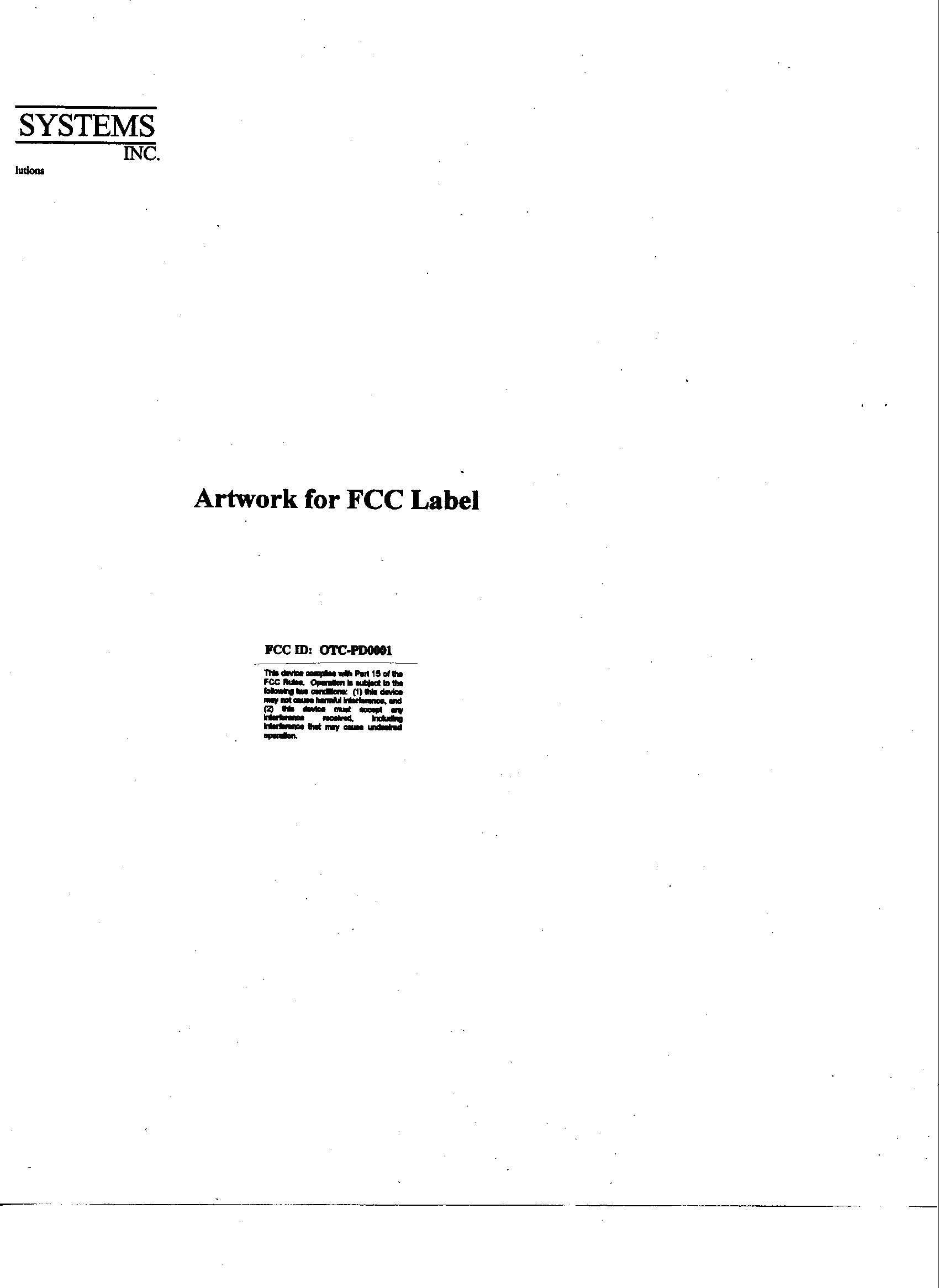
FCC Label Location FCC Label Location
Test Report
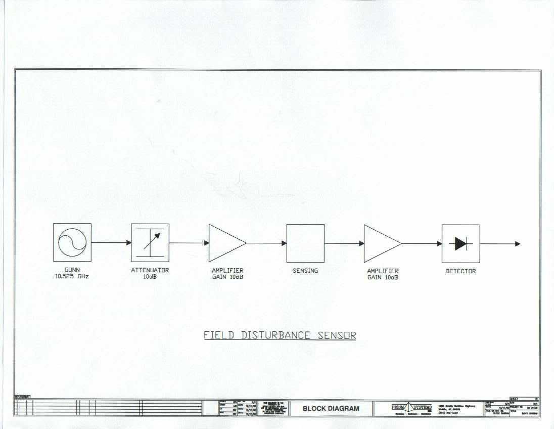
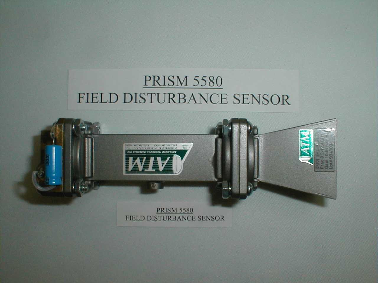
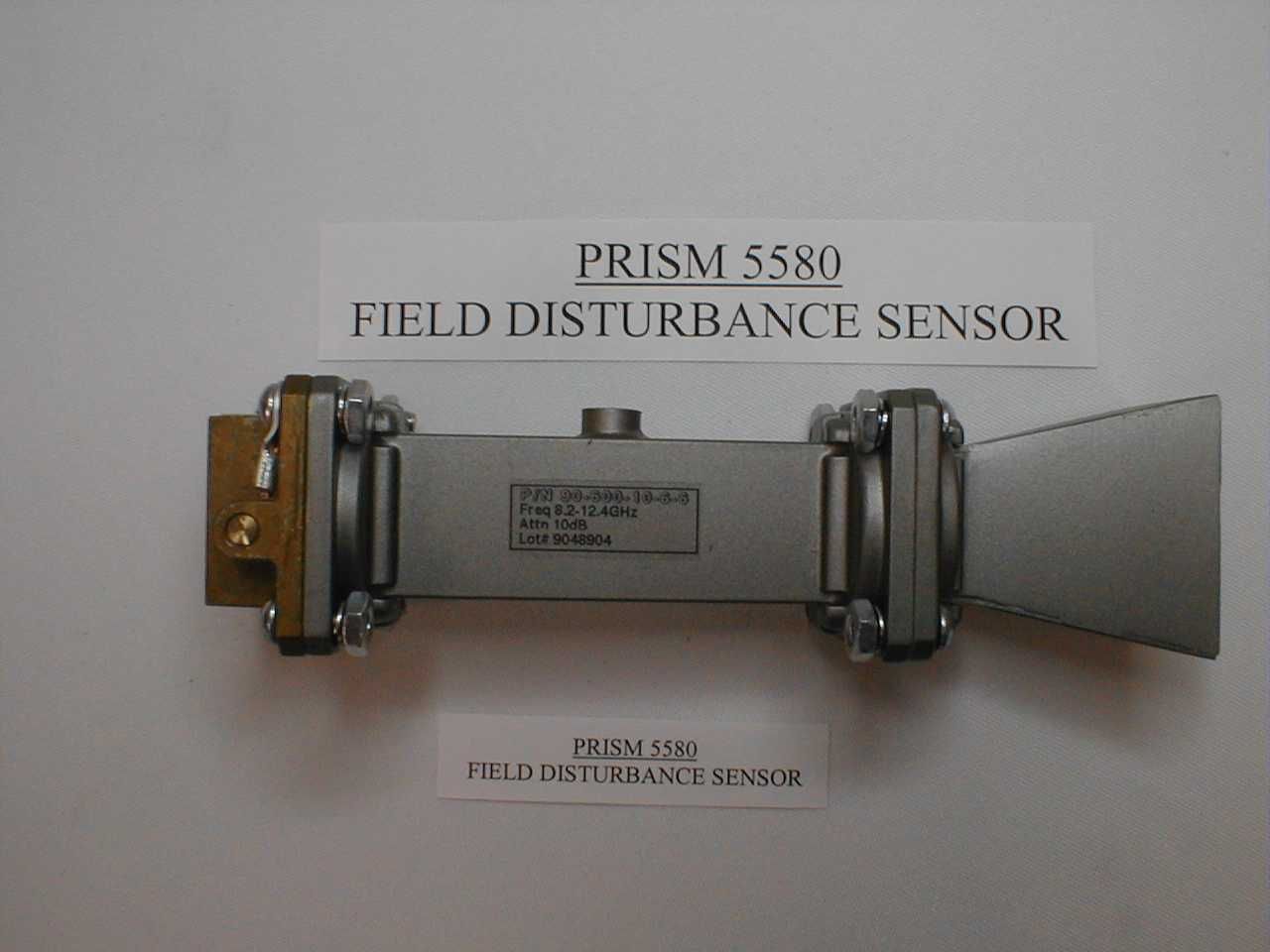
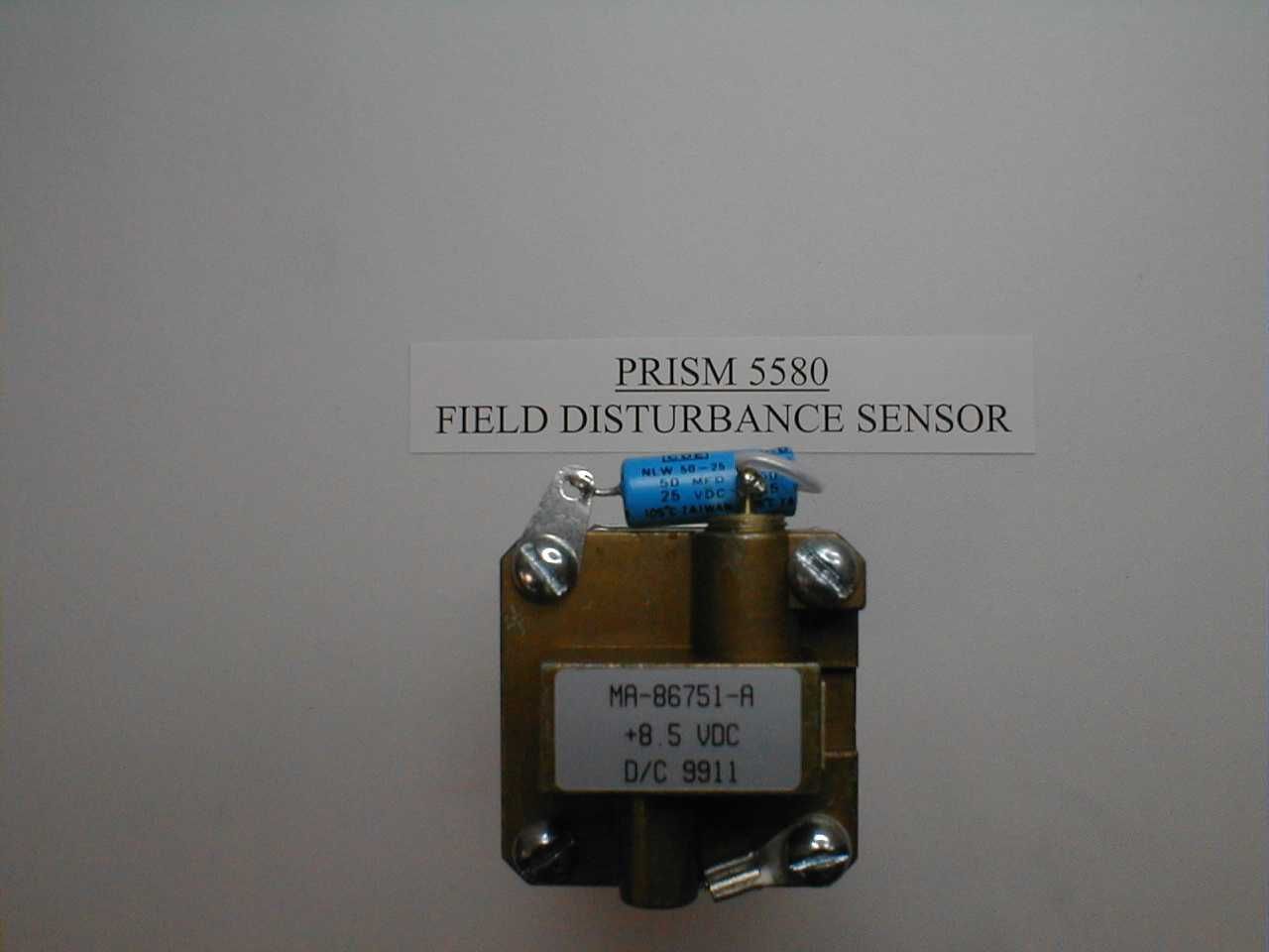
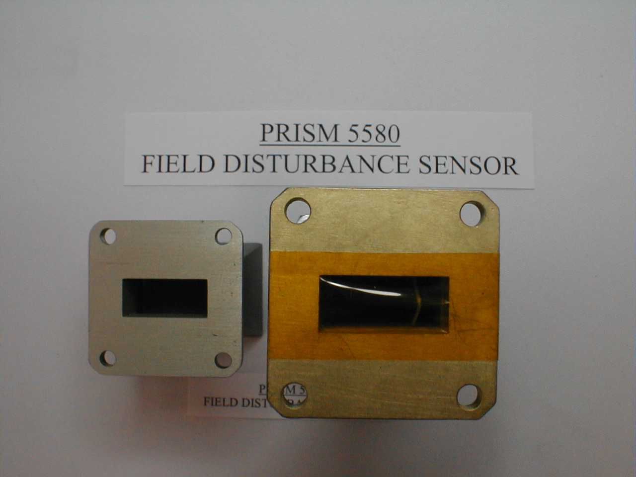
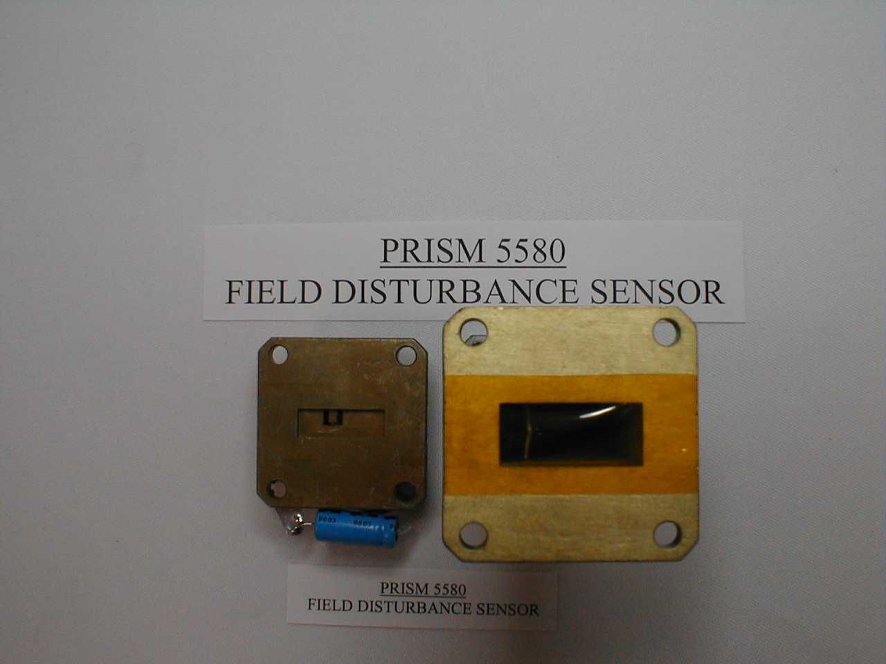
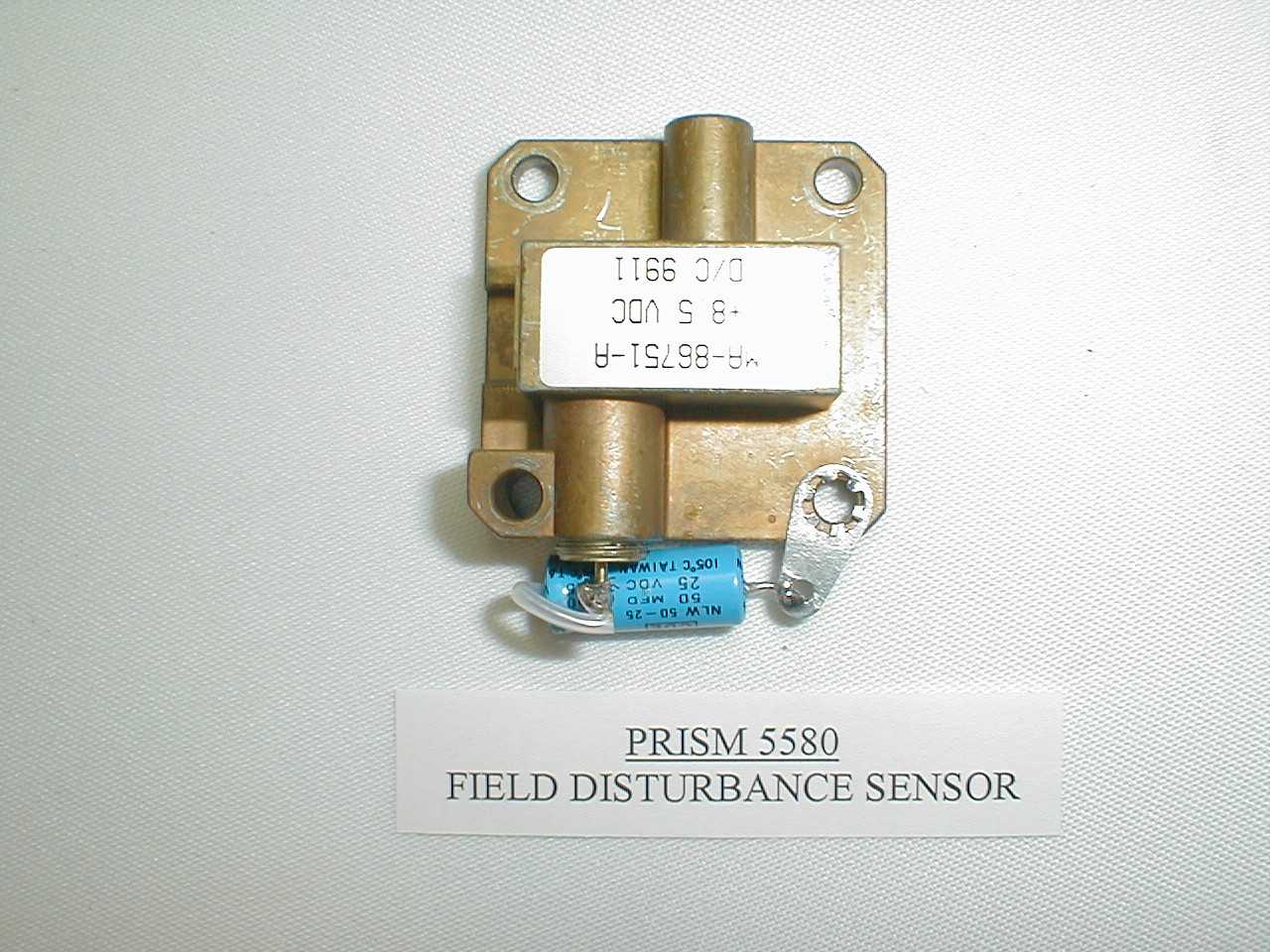
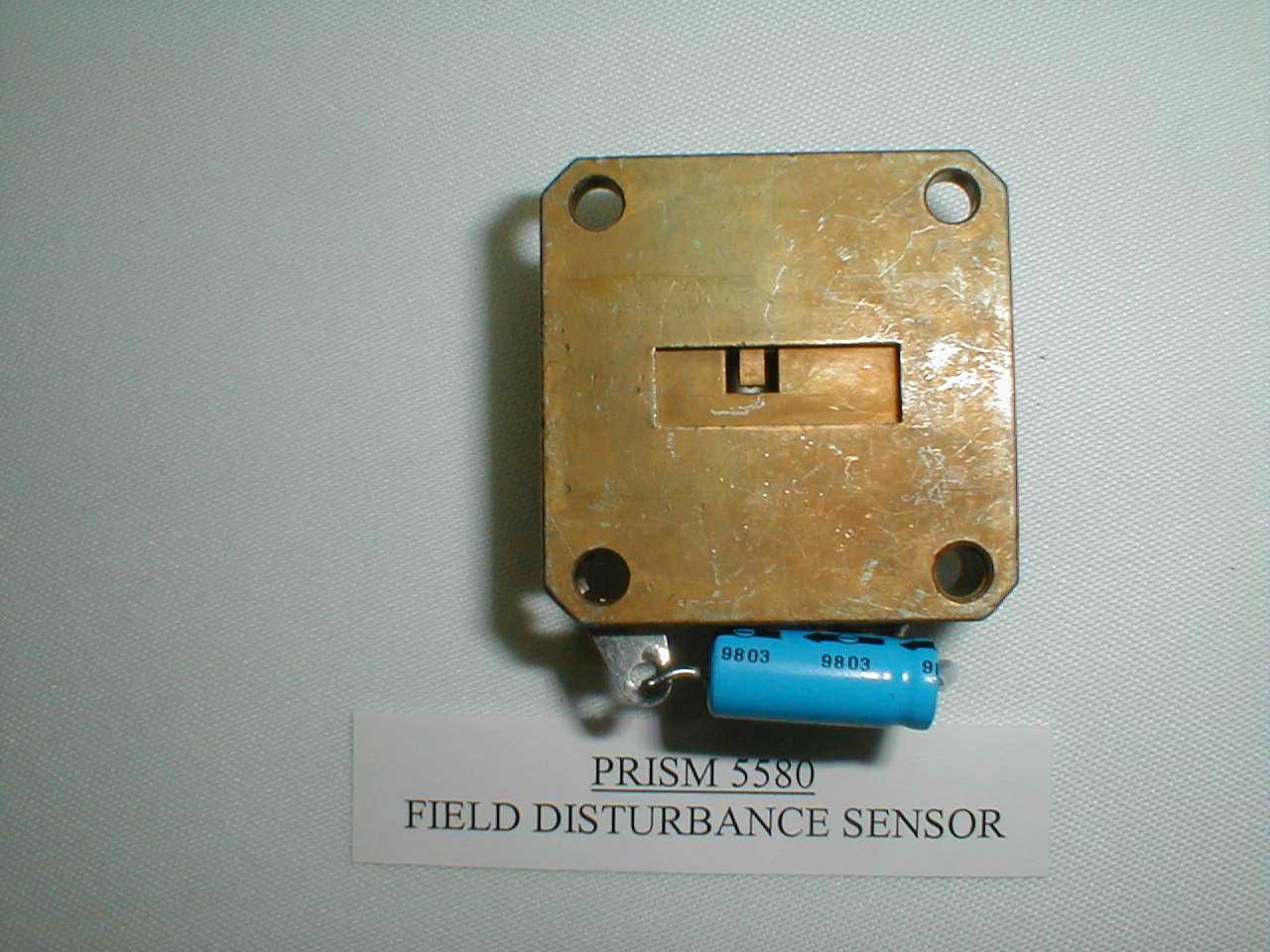
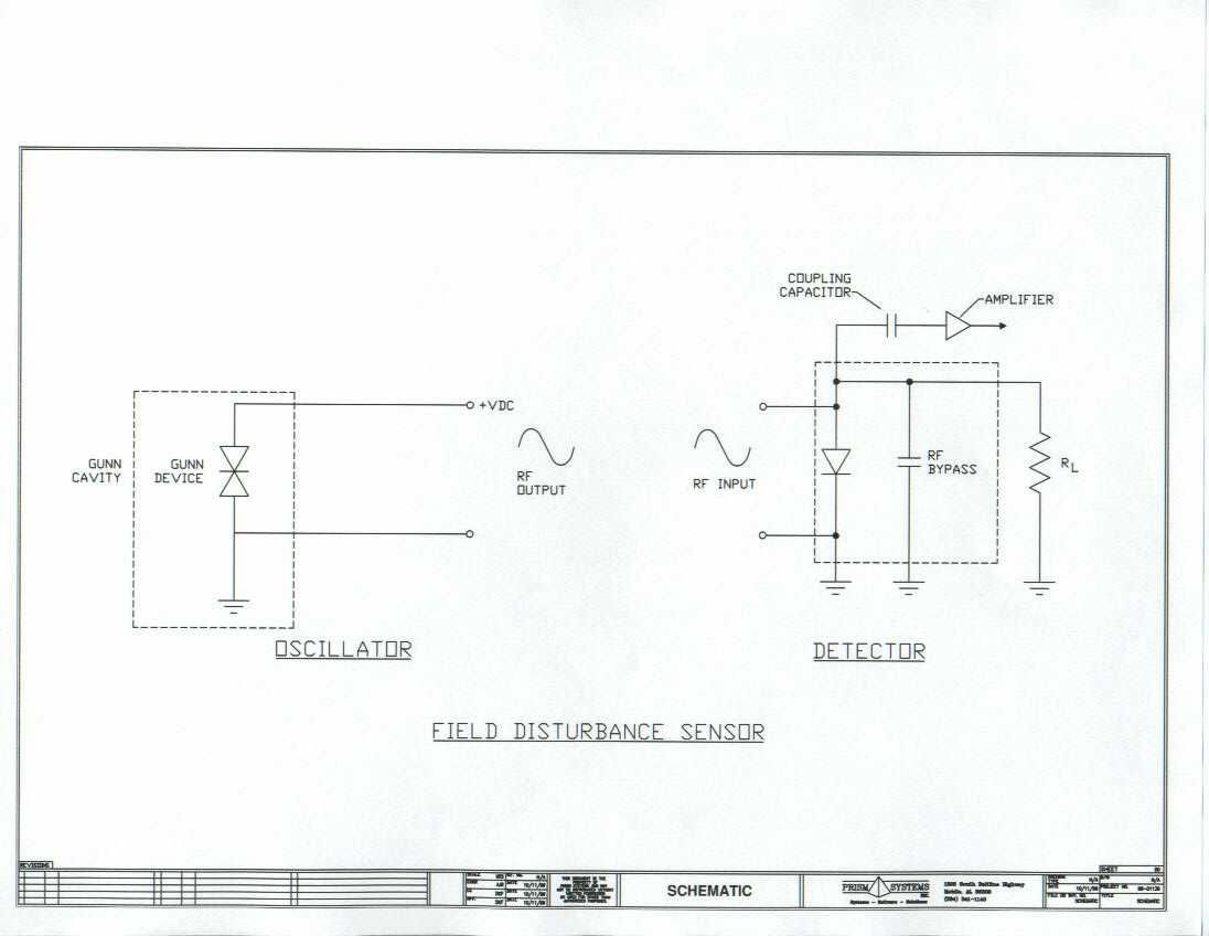
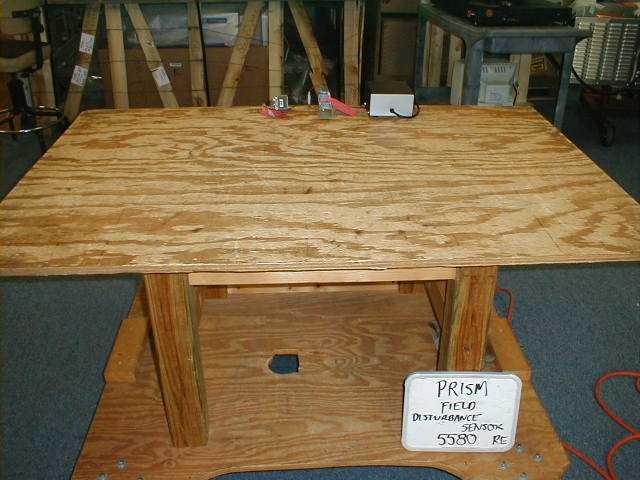
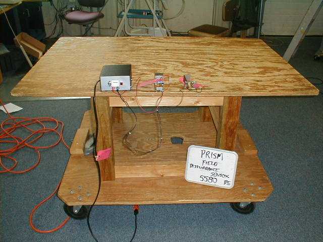
FCC CERTIFICATION TEST REPORT for Prism Systems, Inc. 200 Virginia Street Mobile, AL 36603 FCC ID: OTC-PD0001 February 5, 2000 WLL PROJECT #: 5580X This report may not be reproduced, except in full, without the prior written consent of Washington Laboratories, Ltd. Prism Systems, Inc. FCC ID: OTC-PD0001 WLL Project #: 5580X i TABLE OF CONTENTS Statement of Qualifications Letter of Agency ____________________________________________________ 1.0INTRODUCTION........................................................................................................................................... 1 1.1S UMMARY...................................................................................................................................................... 1 2.0DESCRIPTION OF EQUIPMENT UNDER TEST (EUT) ......................................................................... 1 2.1O N-BOARD OSCILLATORS.............................................................................................................................. 1 3.0TEST CONFIGURATION ............................................................................................................................. 2 3.1T ESTING ALGORITHM..................................................................................................................................... 2 3.2C ONDUCTED EMISSIONS TESTING.................................................................................................................. 2 3.3R ADIATED EMISSIONS TESTING...................................................................................................................... 2 3.3.1Radiated Data Reduction and Reporting............................................................................................. 3 FCC 15.245 3M Radiated Emissions Data – Site 1 .............................................................................................................4 TABLES Table 1.Conducted Emissions Results Table 2.System Under Test Table 3.Interface Cables Used Table 4.Measurement Equipment Used APPENDICES Appendix A.Statement of Measurement Uncertainty Prism Systems, Inc. FCC ID: OTC-PD0001 WLL Project #: 5580X 1 FCC CERTIFICATION TEST REPORT for FCC ID: OTC-PD0001 1.0Introduction This report has been prepared on behalf of Prism Systems, Inc. to support the attached Application for Equipment Authorization. The test and application are submitted for a Field Disturbance Sensor under Part 15.245 of the FCC Rules and Regulations. The Equipment Under Test was the Prism Systems, Inc. Field Disturbance Sensor Transmitter. All measurements herein were performed according to the 1992 version of ANSI C63.4. The measurement equipment conforms to ANSI C63.2 Specifications for Electromagnetic Noise and field Strength Instrumentation. Calibration checks are made periodically to verify proper performance of the measuring instrumentation. All measurements are performed at Washington Laboratories, Ltd. test center in Gaithersburg, MD. Site description and site attenuation data have been placed on file with the FCC's Sampling and Measurements Branch at the FCC laboratory in Columbia, MD. Washington Laboratories, Ltd. has been accepted by the FCC and approved by NIST NVLAP (NVLAP Lab Code: 200066-0) as an independent FCC test laboratory. All results reported herein relate only to the equipment tested. The measurement uncertainty of the data contained herein is ±2.3 dB. Refer to Appendix A for Statement of Measurement Uncertainty. This report shall not be used to claim product endorsement by NVLAP or any agency of the US Government. 1.1Summary The Prism Systems, Inc. Field Disturbance Sensor complies with the limits for a Field Disturbance Sensor under Part 15.245 of the FCC Rules and Regulations. 2.0Description of Equipment Under Test (EUT) The Prism Systems, Inc. RF transmitter (EUT) is a field disturbance sensor to serve as a component of a packaged goods inspection system used on a high speed assembly line. The unit operates at the X-band frequency of 10.525GHz. The EUT consists of two parts, an oscillator (Gunn Diode) and a detector (Schottky Diode). Both the oscillator and the detector are mechanically rugged and built into WR-90 wavequide housings. 2.1On-board Oscillators The Prism Systems, Inc. Field Disturbance Sensor contains a 10.525GHz Gunn Oscillator. Prism Systems, Inc. FCC ID: OTC-PD0001 WLL Project #: 5580X 2 3.0Test Configuration To complete the test configuration required by the FCC, the transmitter was powered on and continuously transmitting to the receiver which was placed at approximately 10” away. All testing was performed at the rated power of 8.5 VDC. I/O PortsI/O Cables DC PowerNon-shielded, ≈1m, DC Power Supply to Transmitter and Receiver 3.1Testing Algorithm The transmitter was turned on and constantly transmitting. Worst case emissions are recorded in the data tables. 3.2Conducted Emissions Testing Conducted emissions testing was not performed as the unit is DC powered. 3.3Radiated Emissions Testing The EUT was placed on an 80 cm high 1 x 1.5 meters non-conductive motorized turntable for radiated emissions testing at 3 meter distance. The emissions from the EUT were measured continuously at every azimuth by rotating the turntable. For emission scans below 1GHz, biconical and log periodic broadband antennas were mounted on an antenna mast to determine the height of maximum emissions. The height of the antenna was varied between 1 and 4 meters. For emissions above 1GHz, broadband horn antennas were used. Both the horizontal and vertical field components were measured. The output from the antenna was connected, via a preamplifier, to the input of the spectrum analyzer. The detector function was set to quasi-peak, peak, or average as appropriate. The measurement bandwidth on the spectrum analyzer system was set to at least 120 kHz, with all post-detector filtering no less than 10 times the measurement bandwidth. For emissions above 1 GHz,…
Text truncated - open the document above for the full version.
Contact Information
Applicant
Dennis Frey(Systems Integrator)
334-341-1140Fax: 334-341-1166
Technical Contact
Washington Laboratories, Ltd.Gregory M Snyder
[email protected]301/417-0220
7560 Lindbergh Drive · Gaithersburg, Maryland · United States
Non-Technical Contact
Washington Laboratories, Ltd.Ann S Miller
[email protected]301/417-0220
Test Firm
Washington Laboratories, Ltd.Michael Violette
Technical Specifications
| # | Rule Parts | Frequency Range | Power Output |
|---|---|---|---|
| 1 | 15C | 10.53 GHz - 10.53 GHz | - |