OTD-SYS400HSAudio Response System
Quick Tally Interactive Systems
Click to zoom
Application Details
- Equipment Class
- DSR - Part 15 Remote Control/Security Device Transceiver
- Date of Grant
- Feb 08, 2000
- Application Purpose
- Original Equipment
- Date of Application
- Nov 22, 1999
- Equipment Note
- Audio Response System
- Frequency Range
- 916.10000000 - 916.90000000
- Country
- United States
Documents & Files
Document Text
Text extracted from the exhibit documents filed with the FCC. Open a document above to read the original.
Test Report
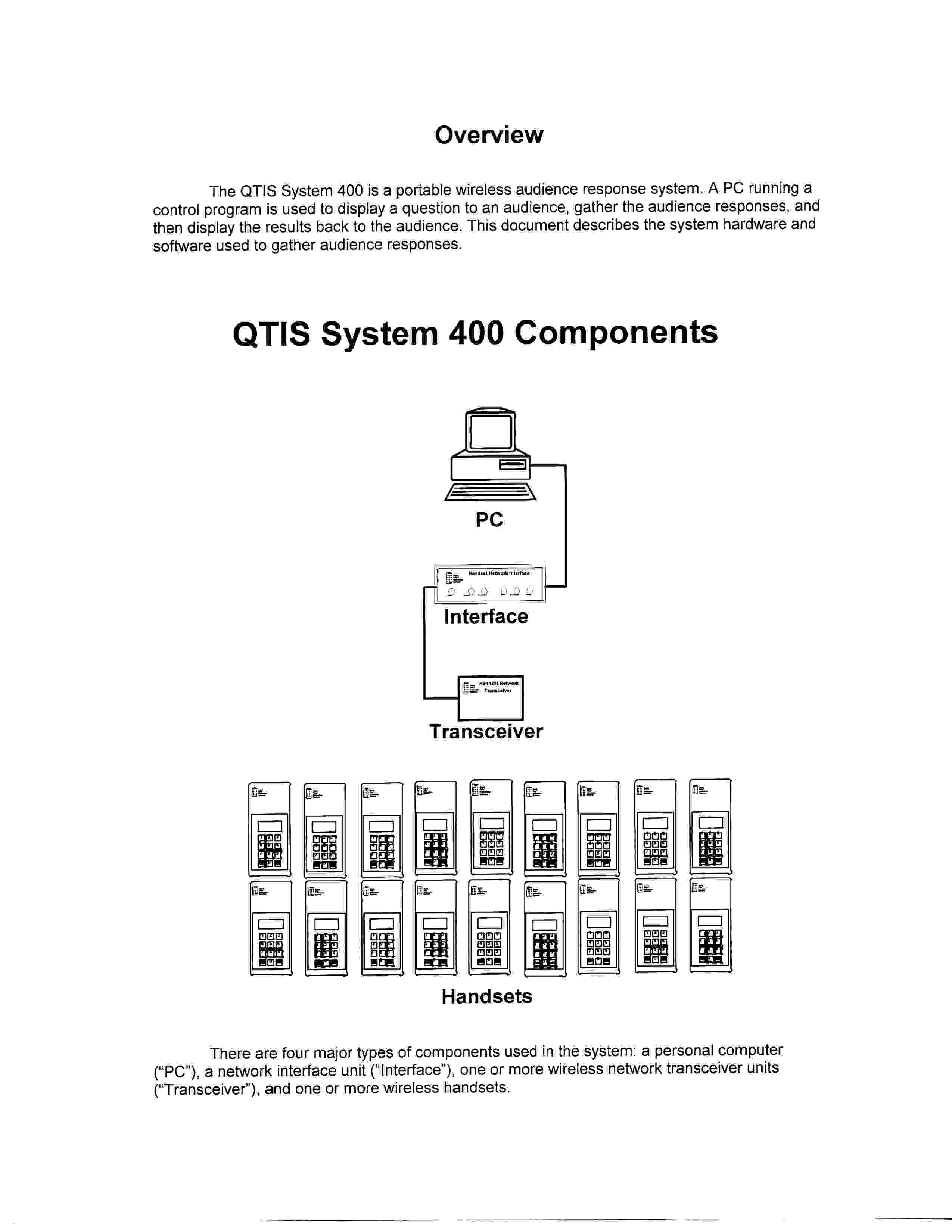
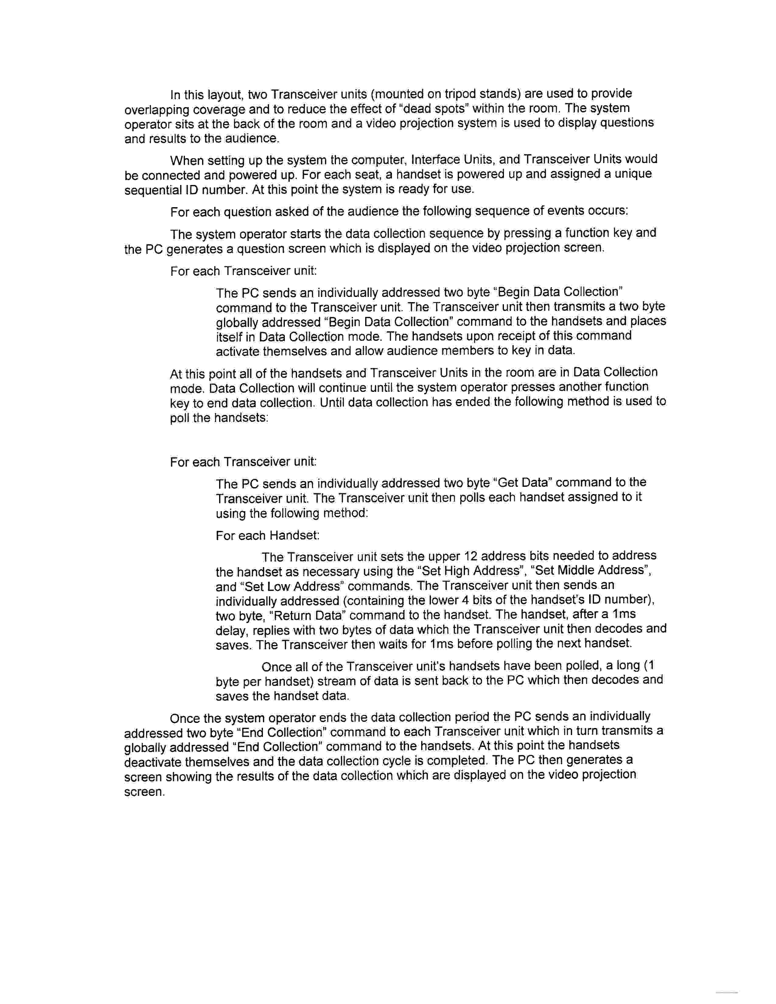
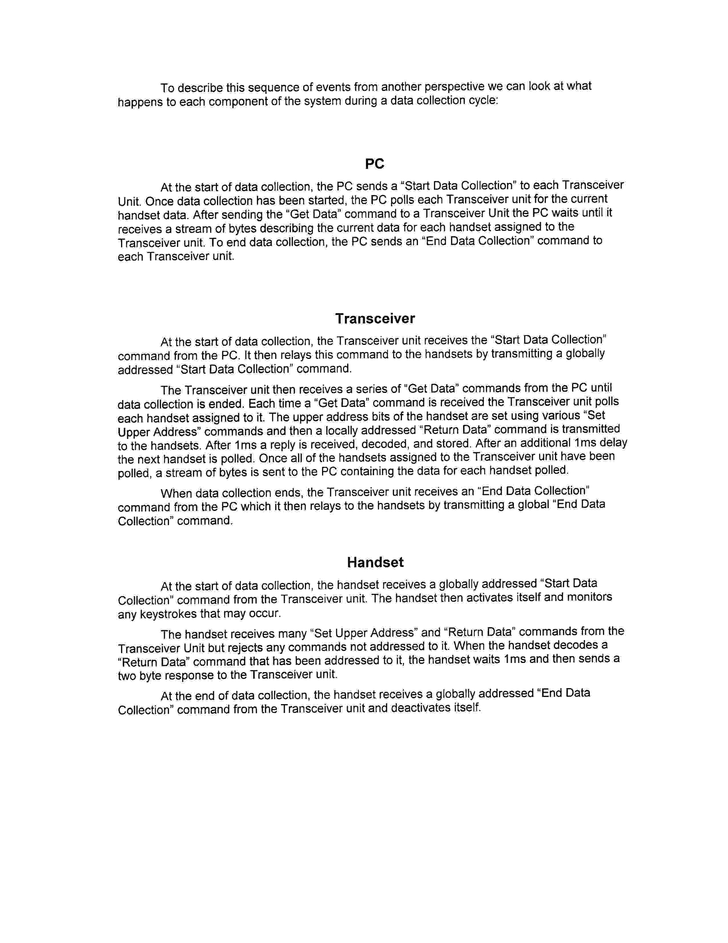
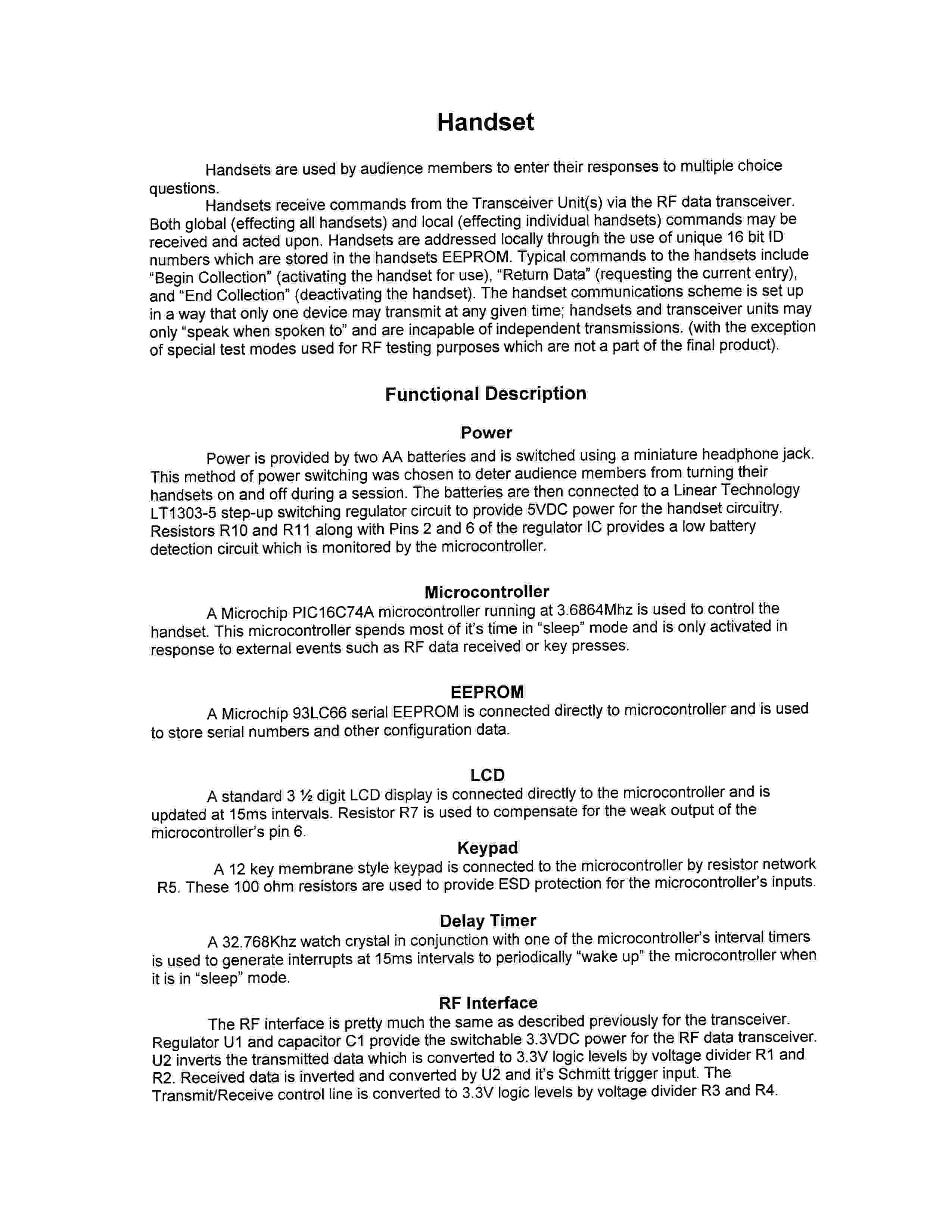
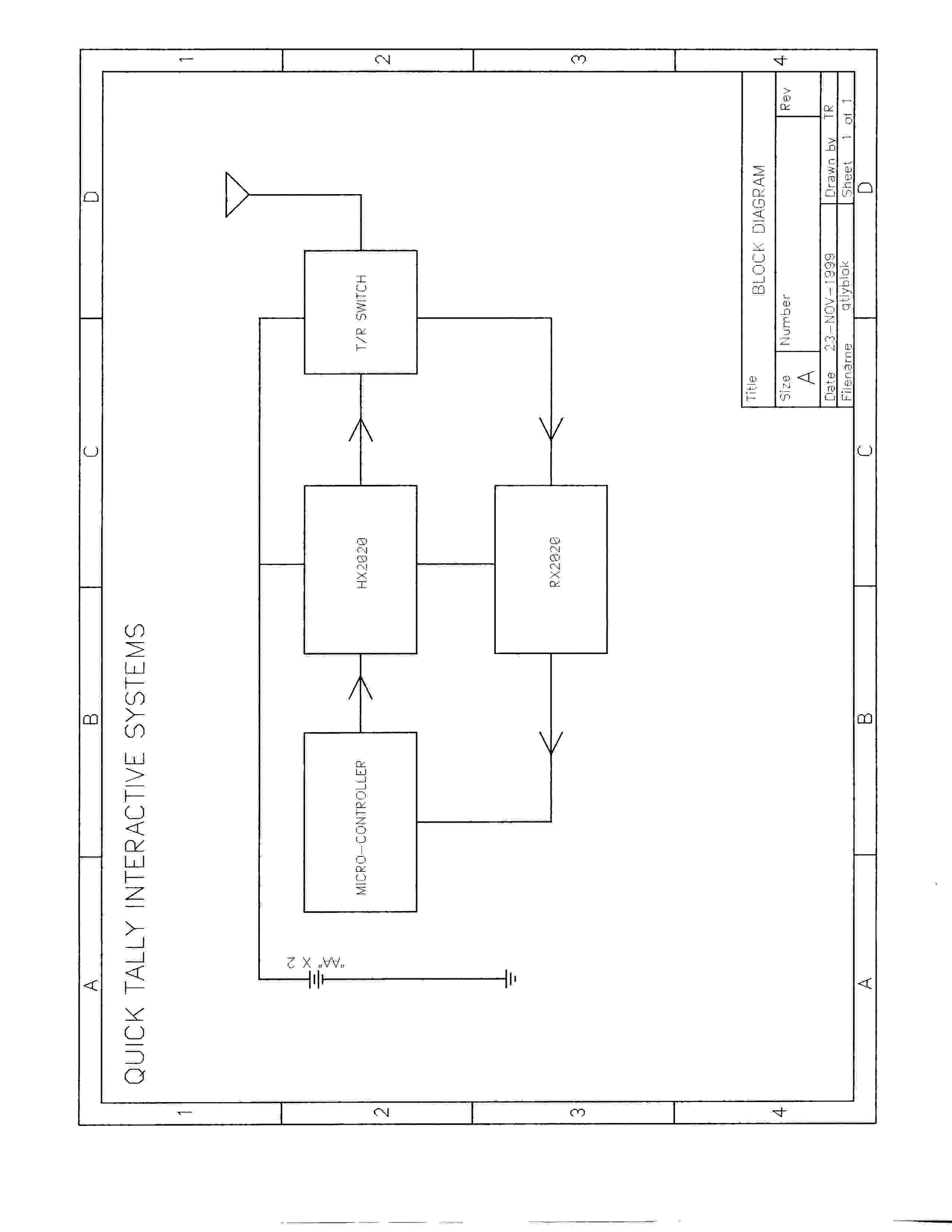
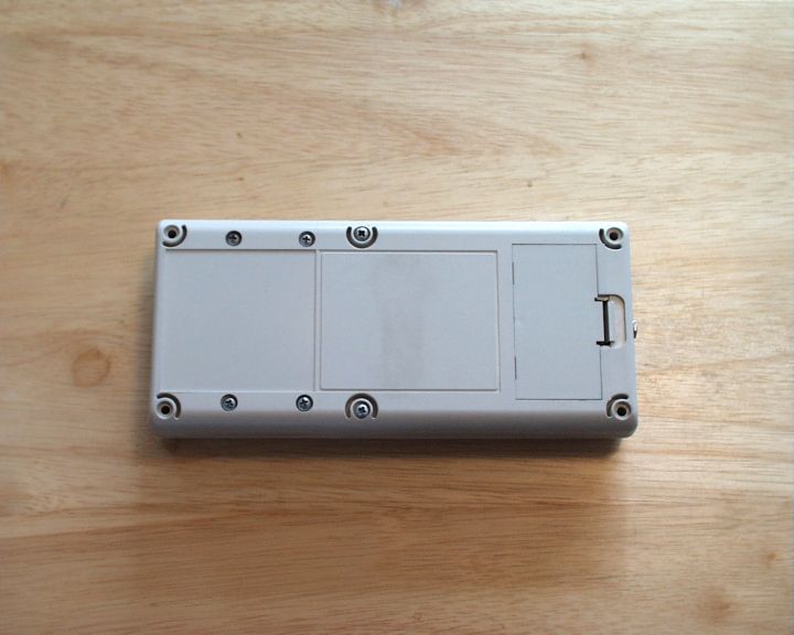
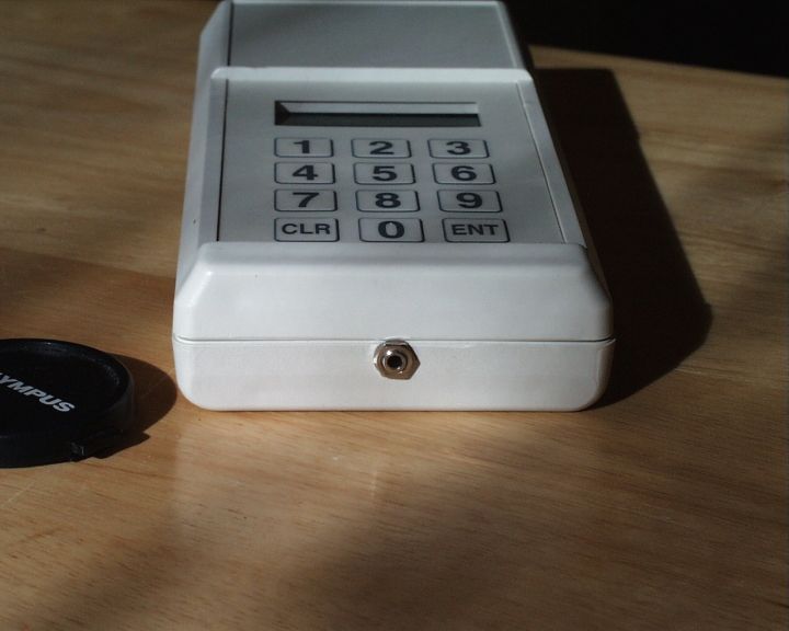
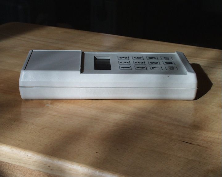
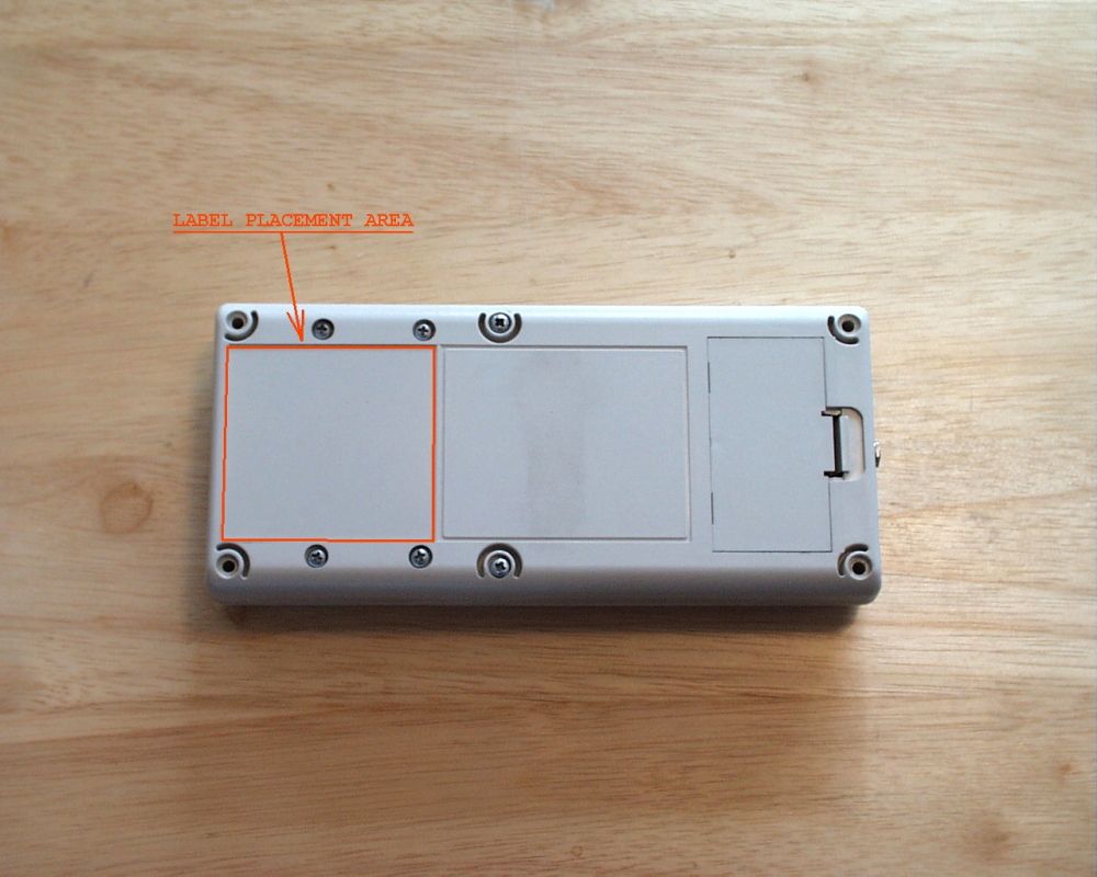
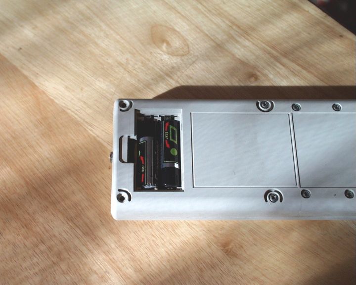
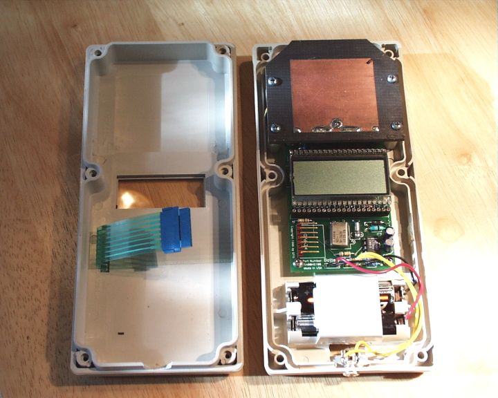
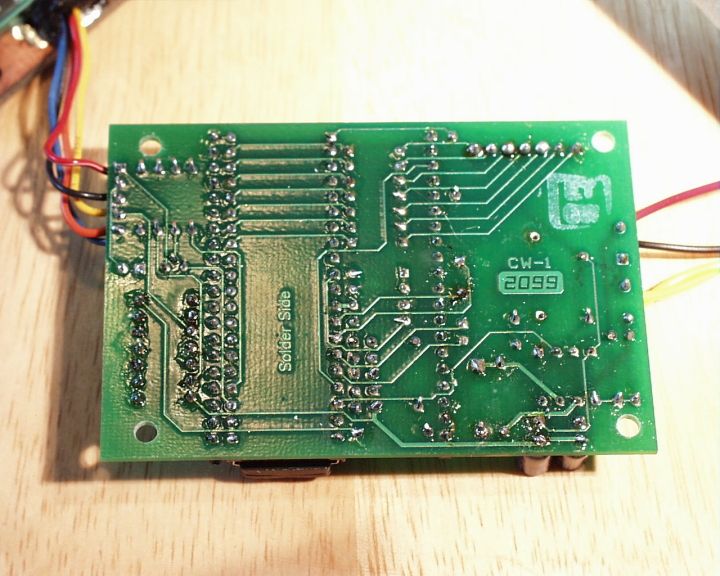
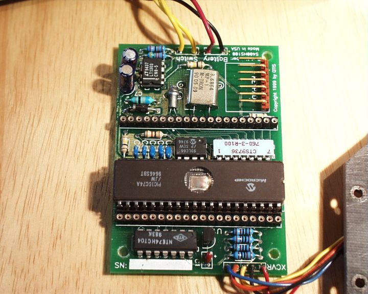
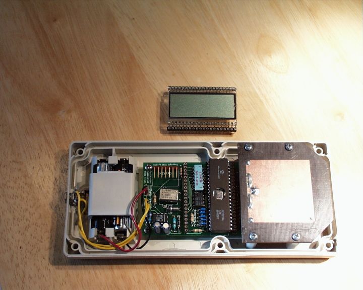
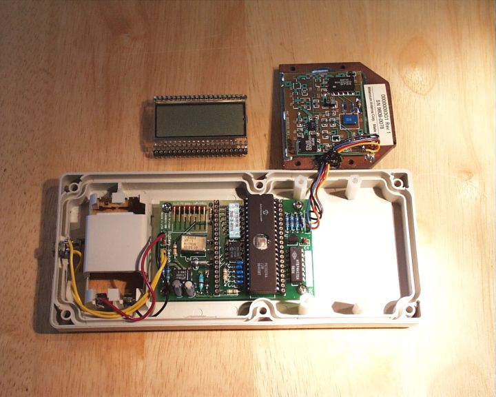
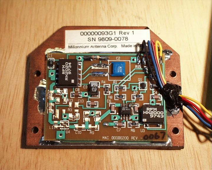
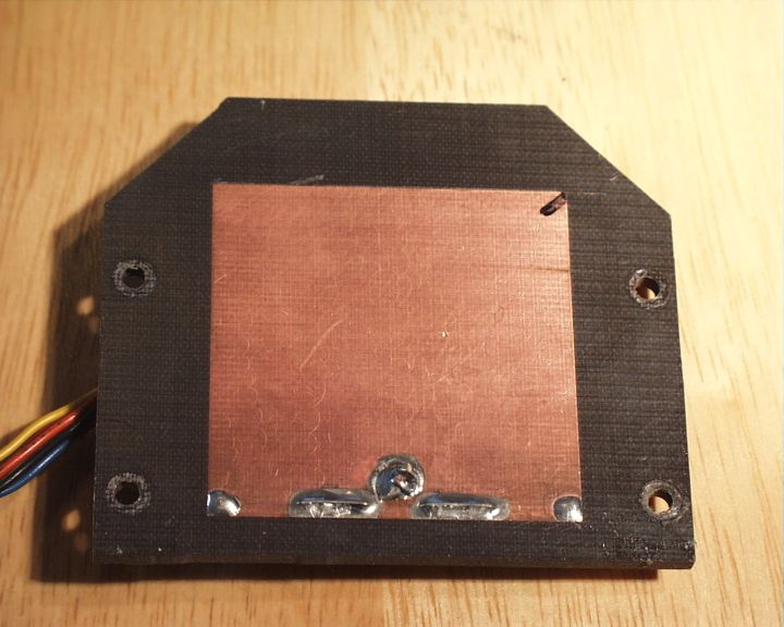
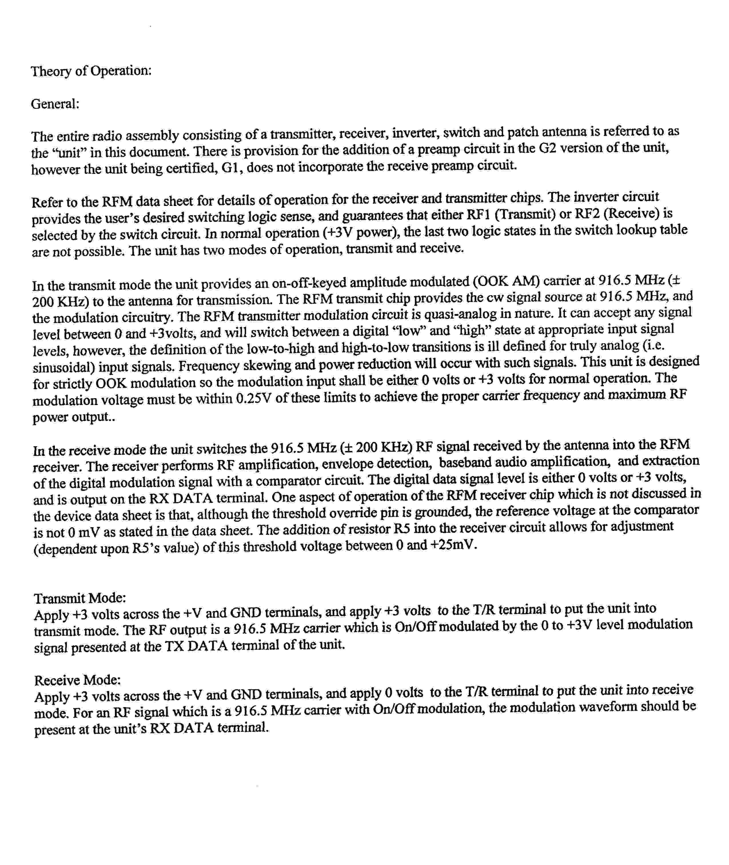
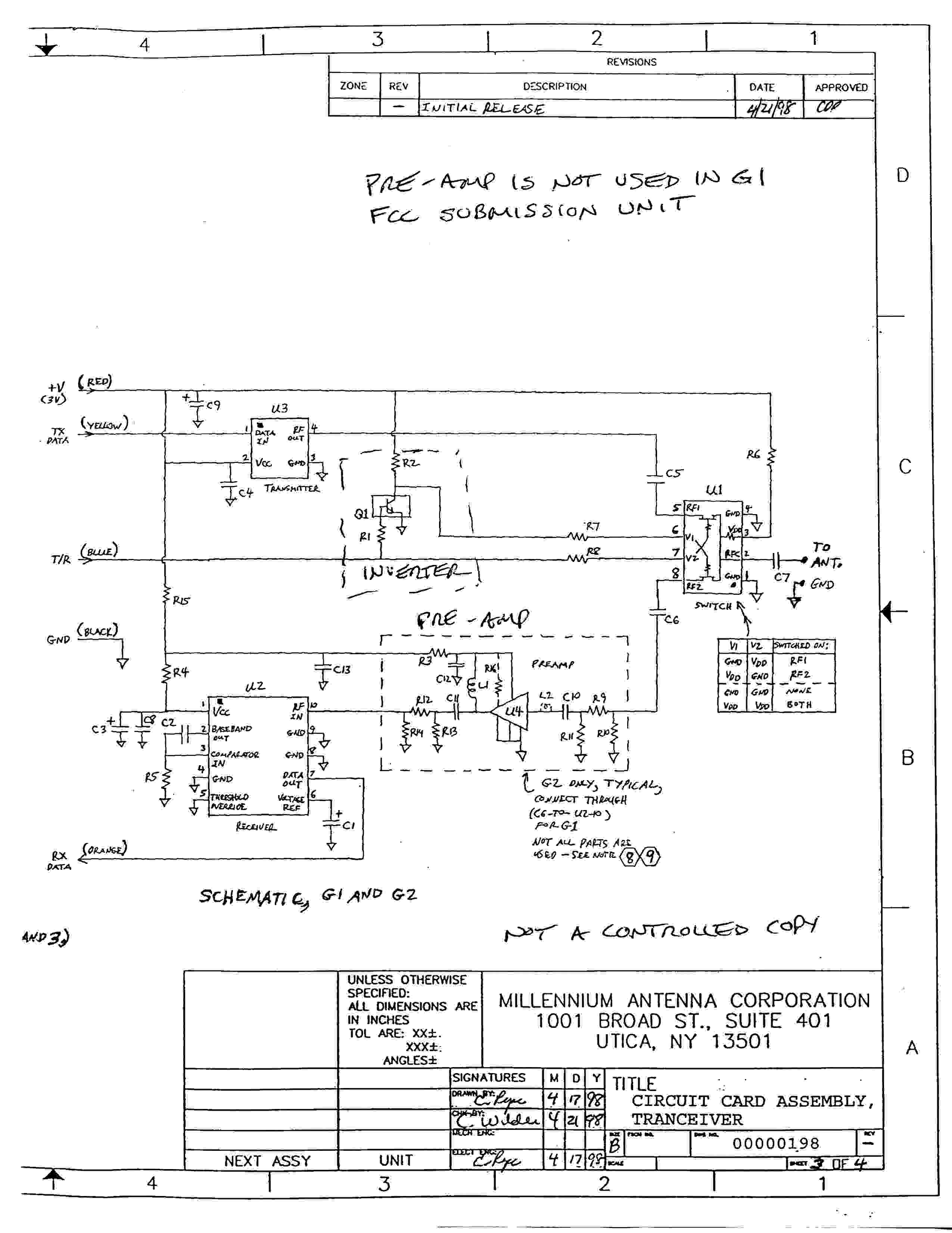
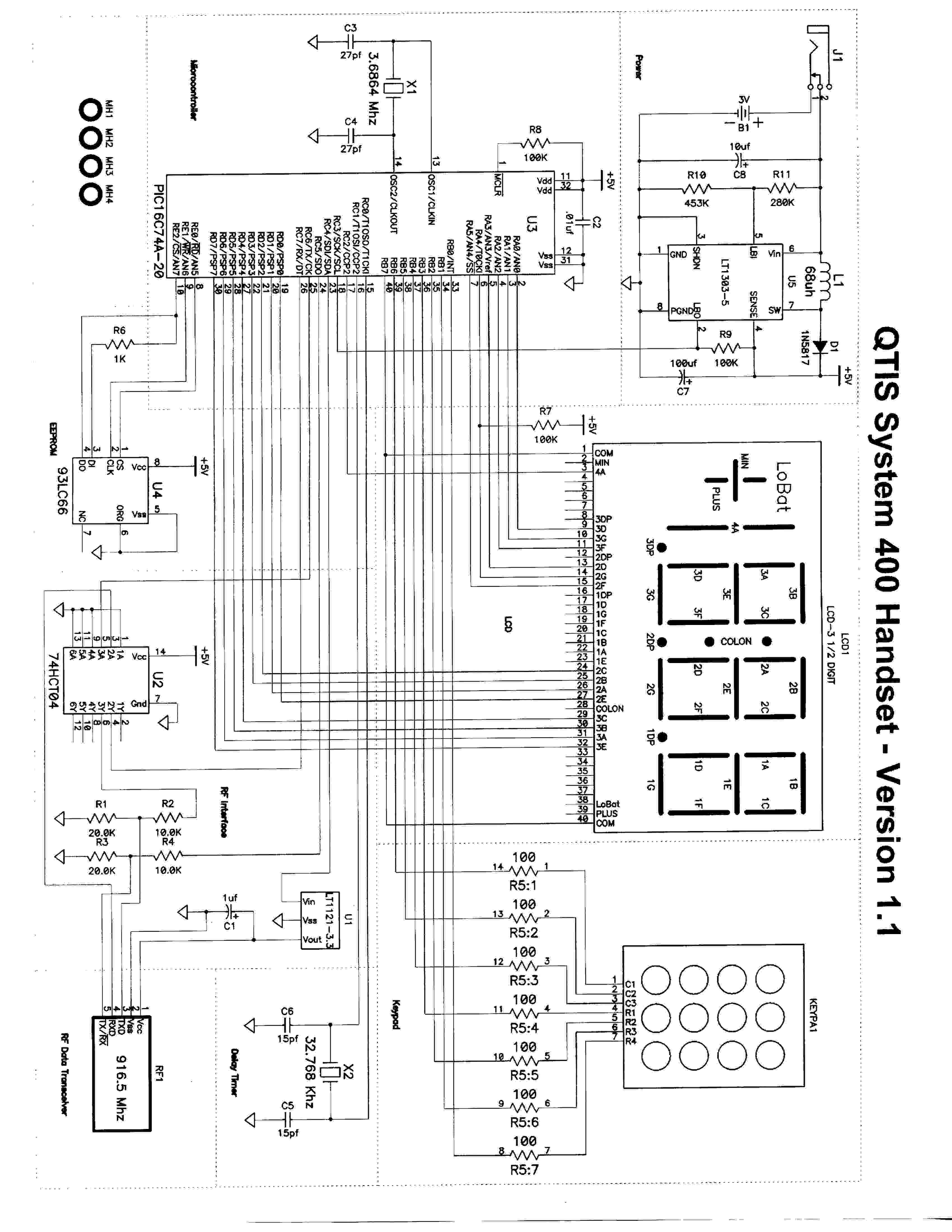
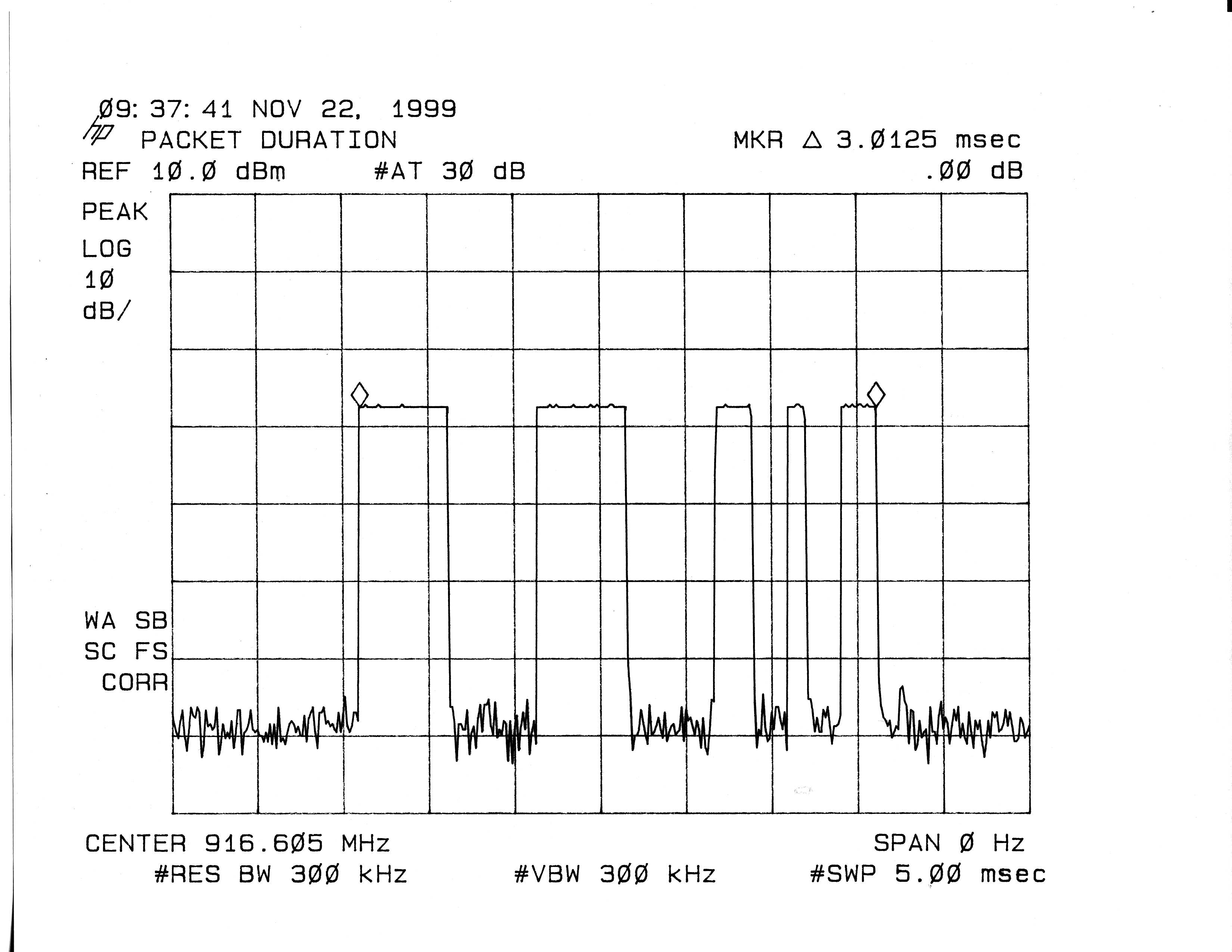
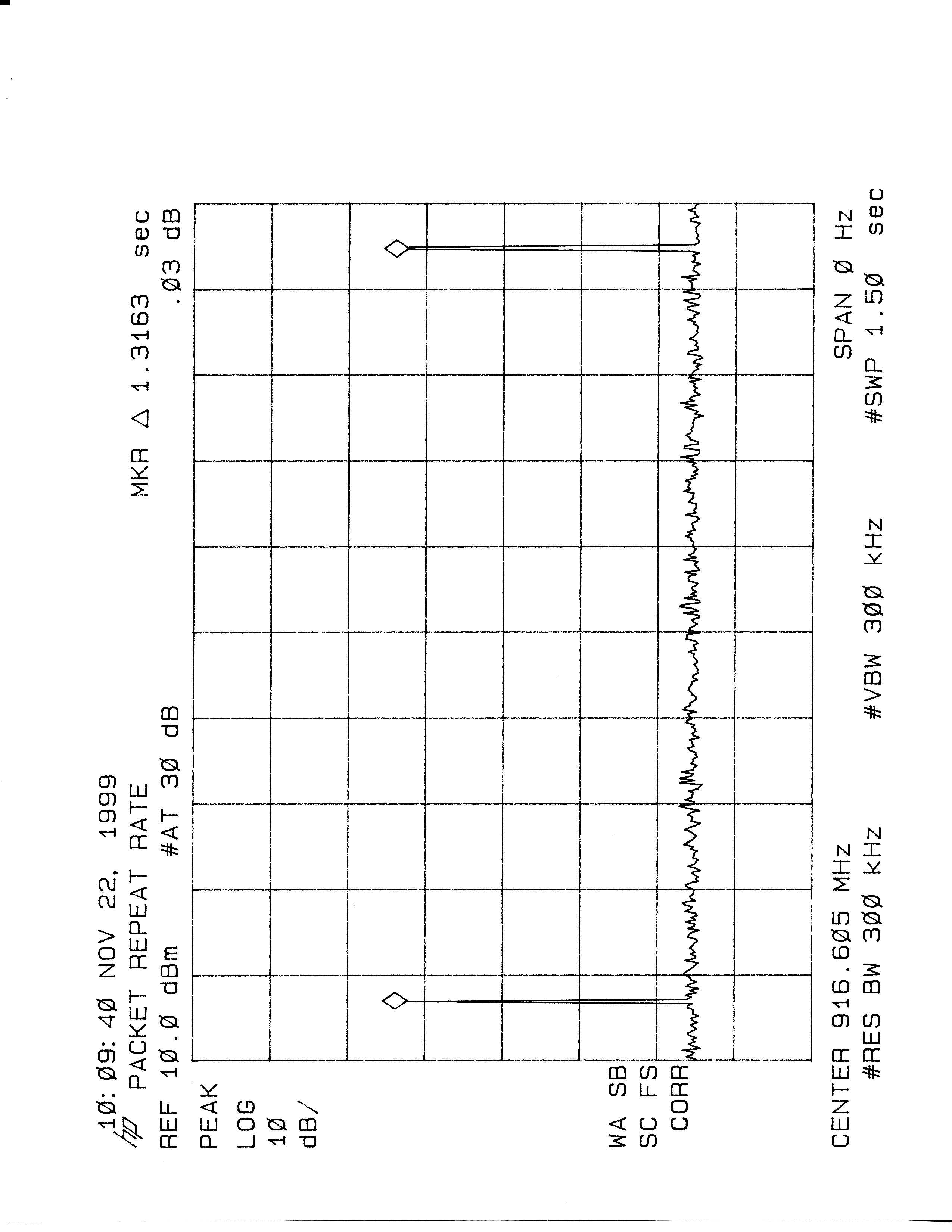
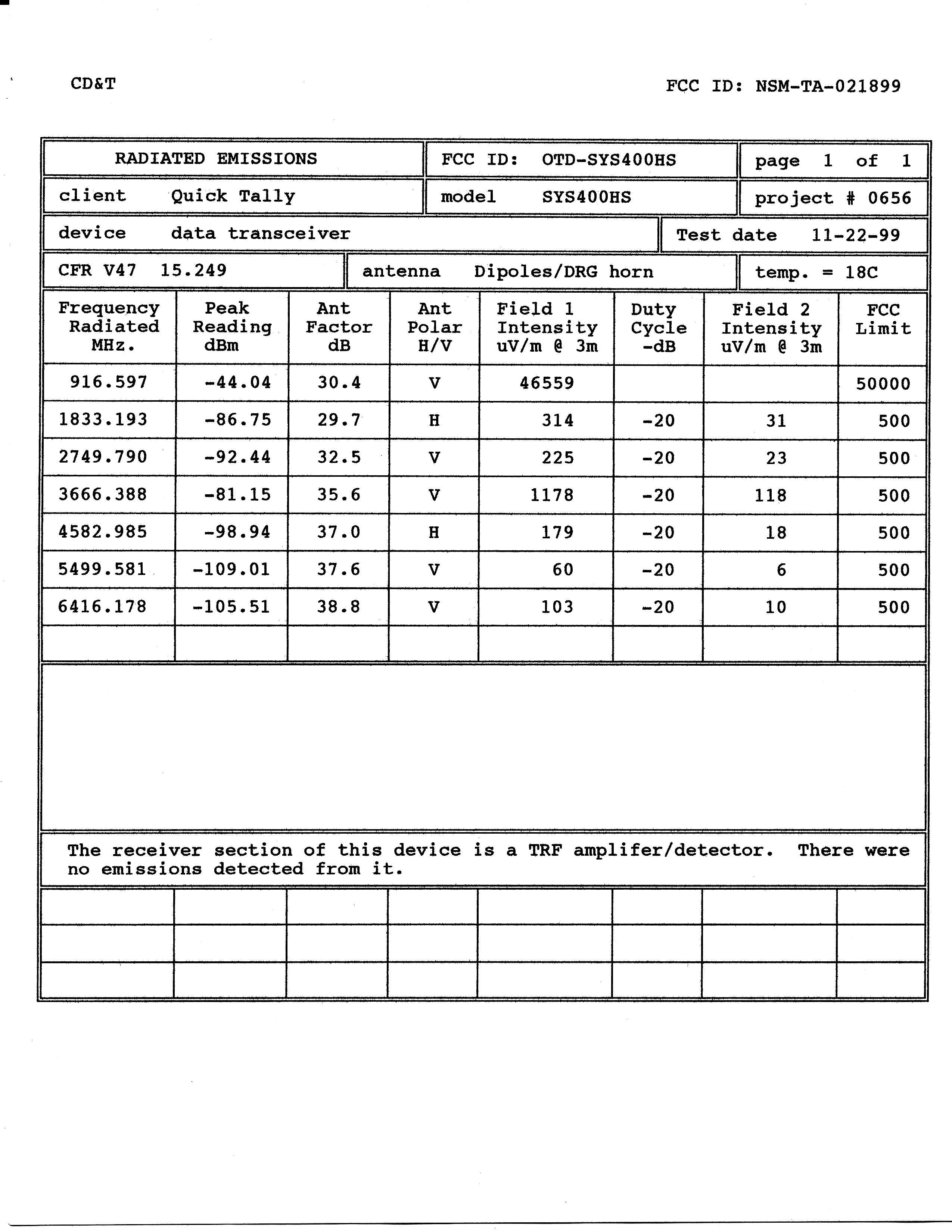
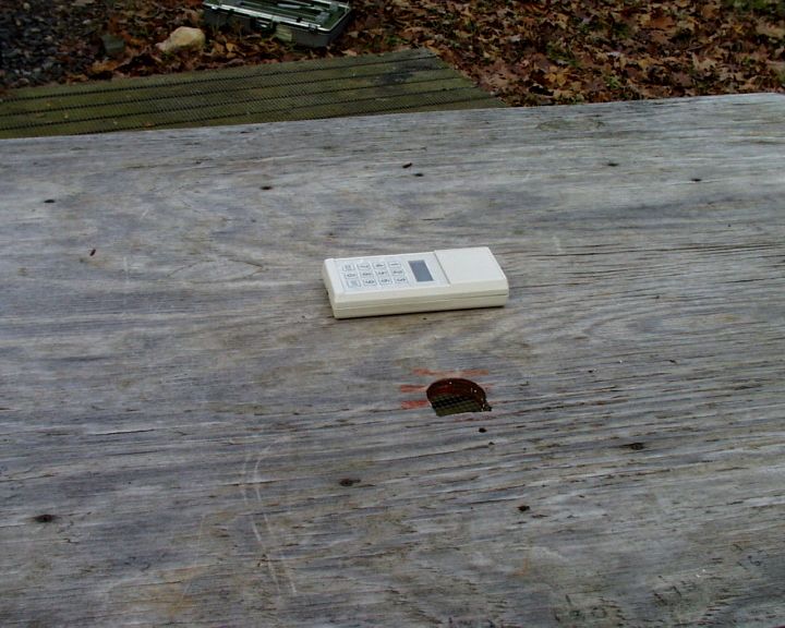
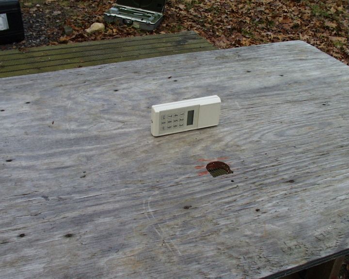
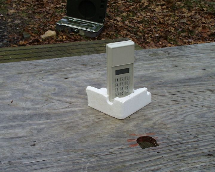
CD&T FCC ID: HS9-RV8310 A. DEVICE UNDER TEST The device is a handheld transceiver powered by 2 internal “AA” batteries. The device is designed to receive and reply to query transmissions from a companion base transmitter (OTD-HNX100). This transceiver has no means to initiate a transmission on its own. It responds only to query transmissions from the base unit. This device operates under Part 15.249 at 916.5MHz nominal. The data format is a pulse position on/off keyed protocol similar to Manchester phase. The response packet duration is approximately 3ms long and is issued one time per each query signal. The base unit can issue up to 160 queries per second but the query interval for any given handset is set at per second (see plots). This results in a duty cycle correction factor of – 30dB. Actually, the correction is slightly greater than –30dB since the response transmission has off spaces within the 3ms packet frame. The net result is a –20dB maximum correction factor as dictated in 15.35. Thus, –20dB was used for the calculations. This receiver of this device is a TRF circuit using SAW filters to achieve the desired receive frequency. A SAW delay line is used to provide a time lag between two rf sequenced amplifiers so that the amplifiers may be alternately turned on and off (approx. 245kHz.) and thus realize a relatively high gain without instability. The entire receiver is contained in a single monolithic integrated circuit. The only external component is the patch antenna. There are no tunable elements in this device. B. MEASUREMENT PROCEDURE: RADIATED EMISSIONS Testing of this device and its associated transceiver (OTD- HNX100) was conducted at the Hyak Labs. test facility in Spotsylvania, Virginia. Field strength measurements were conducted according to the procedures set forth in ANSI C63.4 (1992). The device was supplied with a special mode in the software that produced a steady 5KHz signal to enable facilitate testing. The plots were captured by evoking response packets from query transmissions from the base transceiver. The device under test was placed on a rotating turntable 0.8 meters high, centered at 3 meters distant from the measurement antenna. The device was placed in the center of the turntable and tested in the three logical positions shown in the test setup photographs. Measurements for the 6 th and 7 th harmonics were taken at 1 meter and factoring –9.54dB into the readings. The field strength measurements were taken using an HP8596E spectrum analyzer, an Avantek UJ210 preamp, an EMCO 3120 dipole set and an EMCO 3115 DRG horn. The device was scanned from 30 MHz. to 10GHz. All emissions were noted. In this case the only emissions detected were those that were harmonically related to the fundamental transmit frequency. At each detected frequency, the device was measured by rotating the turntable and adjusting the antenna height over a range of 1 to 4 meters to obtain the maximum output level. This procedure was performed with both horizontal and vertical polarizations with the device in the positions described above. The peak reading for each frequency was recorded in the second column on the data sheet. No measurable emissions were evident above 6.5GHz.
Contact Information
Applicant
Alan Warshaw(President)
(323) 653-5303Fax: (323 653-2725
Technical Contact
Control Design and TestingThomas W. Roche W Roche
[email protected](540) 582-2826
6010 Red Fox Drive · Spotsylvania, Virginia · United States
Technical Specifications
| # | Rule Parts | Frequency Range | Power Output |
|---|---|---|---|
| 1 | 15C | 916.1 MHz - 916.9 MHz | - |
Other Applications from Quick Tally Interactive Systems

OTD-HNX100
Dec 22, 1999Network Transceiver
Equipment Class
DXT - Part 15 Low Power Transceiver, Rx Verified