OTECPS1000Electronic Cover System RX
Sol-A-Raj CorporationApplication Details
- Equipment Class
- CRR - Superregenerative Receiver
- Date of Grant
- Jan 12, 2000
- Application Purpose
- Original Equipment
- Date of Application
- Nov 23, 1999
- Equipment Note
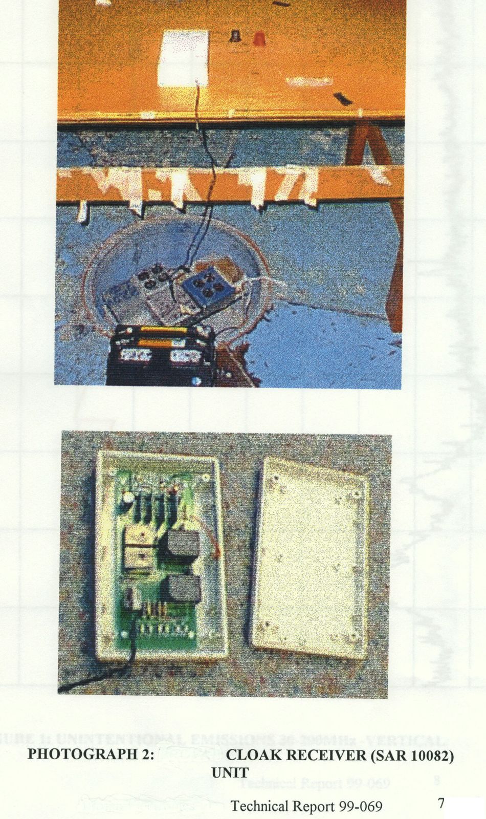
- Electronic Cover System RX
- Frequency Range
- 424.40000000 - 424.40000000
- Company
- Sol-A-Raj Corporation
- Country
- United States
Documents & Files



Document Text
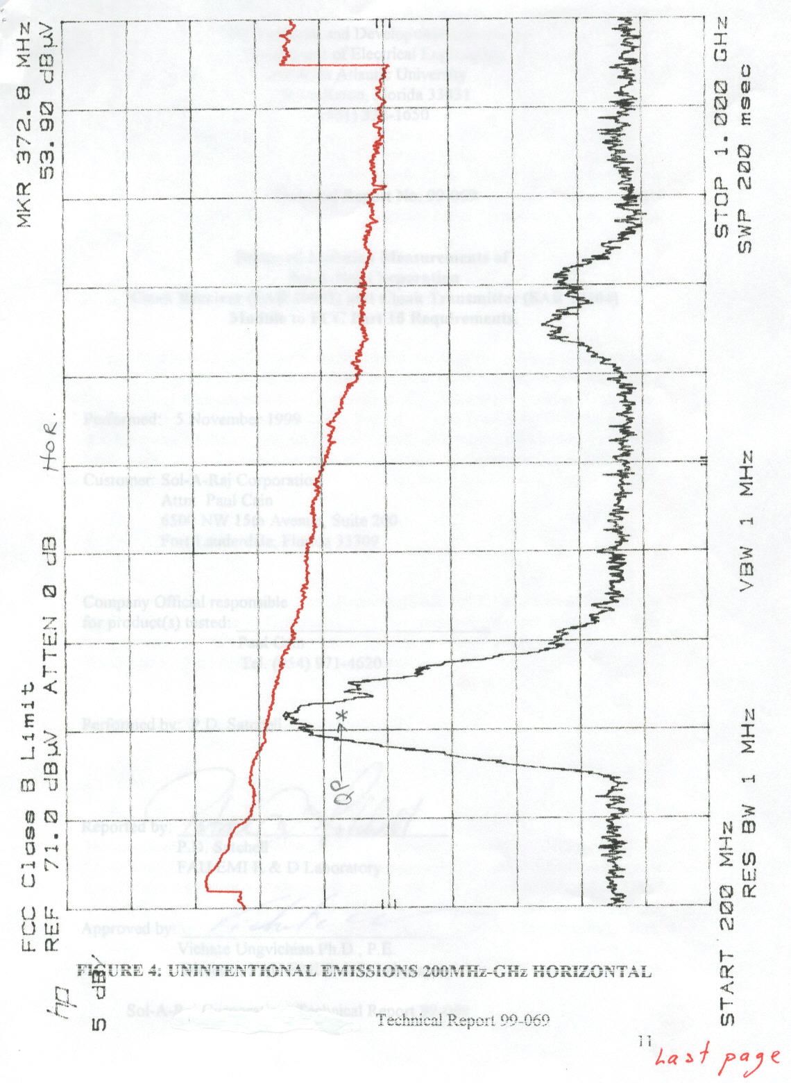
Text extracted from the exhibit documents filed with the FCC. Open a document above to read the original.
Users Manual
COVER DEPLOYMENT COVER REMOVAL 1 ) Grasp the CLOAK door in your right hand with thumb finding the left 1 ) Pull the cover up and over the passenger side mirror and front left bumper, indentation in the system door. Rotate your wrist to the right and the door making sure the cover has cleared the mirror. ( Fig. 1 ) will pop open. ( Fig. 1 ) 2 ) Facin g the front of the vehicle, g ras p the s y stem handle in y our ri g ht hand an d 2 ) Gras p the s y stem handle in y our ri g ht hand and ad j ust so the handle twist to the right to remove it from the front clip. ( Fig. 2 ) control buttons are directly under your thumb. ( Fig. 2 ) Fig. 1 Fig. 2 Fig. 1 Fig. 2 3 ) To begin cover deployment, press the OUT button and hold. The cover will 3 ) Keep the handle low as you back slightly away towards the bumper on the continue to move as long as the button is depressed. ( Fig. 3 ) driver's side, ensuring the elastic hem clears from under the bumper. ( Fig. 3 ) 4 ) Hold the button for approximately five seconds, then begin to walk to the 4 ) Make sure the cover clears the driver's side mirror, then, walk the cover front of the vehicle while holding the handle high over the center and top of the towards the rear of the vehicle. About midway to the rear, press the IN vehicle. The objective is to deploy the cover with gentle tension so that it stays button. ( Fig. 4 ) on the top and center of the vehicle. This is achieved by walking slightly faster than the system presents the cover. Avoid excessive tension. ( Fig. 4 ) Fig. 3 Fig. 4 Fig. 3 Fig. 4 5 ) When you reach the front of the vehicle, and you judge the cover is 5 ) Accelerate your pace so you are directly behind the vehicle when there sufficiently deployed, release the OUT button. Grasp the barrel of the handle is still about six feet of cover outside the cover's container. ( Fig. 5 ) with your left hand, grab a handful of the cover just above the narrow trace with 6 ) Now, grab the trace and gently, but firmly, pull, stretching the elastic hem as your right hand, and gently stretch the cover's elastic so you can snap the the rest of the cover is retracted. This helps elim inate any air that may be handle barrel into the front bumper clip with your left hand. ( Fig. 5 ) trapped. ( Fig. 6 ) 6 ) Now, stretch the left hem of the cover over the passenger side mirror and then down over the bumper. Repeat this process on the driver's side. ( Fig. 6 ) Fig. 5 Fig. 6 Fig. 5 Fig. 6 7 ) Walk to the back of the vehicle and gently pull the cover enough to tuck the 7 ) Stop pressing the button when there is about a foot of trace left. Place the tip elastic under each side of the bumper. ( Fig. 7 ) of the barrel into the right side of the retaining clip. Press forward until there is 8 ) Close the system door by locating the left indentation on the door and enough clearance to dock the rear of the handle. ( Fig. 7 ) rotate your wrist to the left. You will hear the latch click. ( Fig. 8 ) 8 ) Close the system door by locating the left indentation on the door and the left. You will hear the latch click. Fig. 7 Fig. 8 Fig. 7 Fig. 8 Insert Photo No. 1 Here Insert Photo No. 2 Here Insert Photo No. 3 Here Insert Photo No. 4 Here Insert Photo No. 9 Here Insert Photo No. 5 Here Insert Photo No. 6 Here Insert Photo No. 7 Here Insert Photo No. 8 Here Insert PhotoNo. 11 Here Insert PhotoNo. 10 HereInsert PhotoNo. 12 Here Insert PhotoNo. 13 Here Insert PhotoNo. 14 Here Insert PhotoNo. 15 Here Insert PhotoNo. 16 Here
Users Manual
The Cloak Installation WIRING HARNESS Installation Kit Includes:1 Cloak unit 7 ) Determine the best route for the wiring harness from the unit to the automobile's 1 wiring harness w/inline fuseholder battery. Keep the wiring harness away from all "hot points", such as the muffler. 2 adjustable brackets Choose points of attachment that are at the highest points of the automobile's 1 tail bracket undercarriage. ( Fig. 7 ) 1 j-clip 8 ) Plug the wiring harness into the unit. ( Fig. 8 ) 5 bolts3 self tapping screws 1 15 AMP Fuse1 ) Measure the distance between frame members and assemble the adjustable brackets accordingly. ( Fig. 1 ) 2 ) Determine the hei g ht from the frame to the lowest p oint and attach the assembled bracket to the frame with the self tapping screw. Adjust height to ensure a clear path from left to right. ( Fig. 2 ) Fig. 7 Fig. 8 9 ) Secure the wiring harness to the chosen points with the hardware supplied. Kee p the excess slack out of the wiring harness, not allowing it to hang down. Attach to points approximately 12" to 15" apart. ( Fig. 9 ) Fig. 1 Fig. 2 10 ) Feed the wiring harness up through the engine compartment, routing it 3 ) Secure the tail bracket with the j-clip. ( Fig. 3 ) along the firewall to the side the automobile's battery resides. ( Fig. 10 ) 4 ) Slide the unit into the bracket and adjust so the door of the unit is just behind the bumper façade. Using the adjusting slots on the brackets, centerthe unit and tighten the bolts at the mounting points on the bracket. ( Fig. 4 ) Fig. 9 Fig. 10 Fig. 3 Fig. 4 11 ) Connect the black wire, from the harness, to ground, and, connect the red 5 ) Slide the unit out of the brackets and permanently attach the tail bracket wire to the battery's positive terminal. ( Fig. 11 ) with the self tapping screw. (Fig. 5 ) 6 ) Slide the unit back into the brackets and realign. Permanently secure 12 ) Insert the fuse into the fuse holder. (Fig. 12 ) the unit to the brackets. ( Fig. 6 ) Fig. 11 Fig. 12 Fig. 5 Fig. 6 Insert photo 5 here Insert photo 6 here Insert photo 3 here Insert photo 4 here Insert photo 1 here Insert photo 2 here Inset photo 7 here Insert photo 8 here Insert photo 10 here Insert photo 9 here Insert photo 12 here Insert photo 11 here
ID Label/Location Info
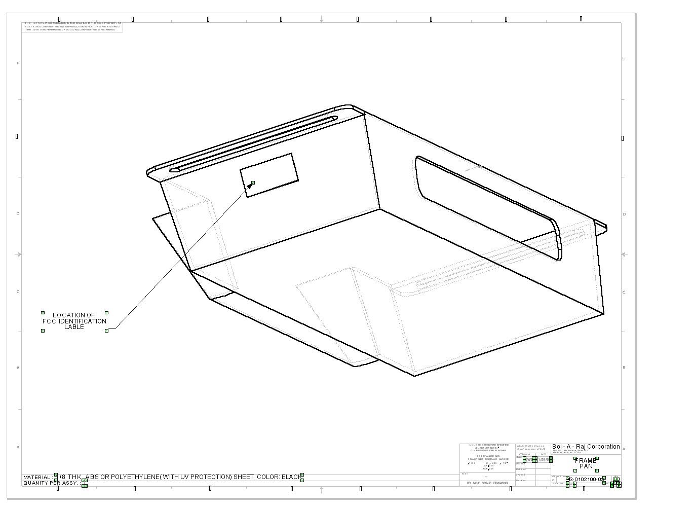
FCC REGULATIONS FCC ID: XXXCPS1000 This device complies with part 15 FCC Rules. Operation is subject to the following two Conditions: (1) this device may not cause Harmful interference, and (2) this device must accept any interference received, including interference that may cause undesired operation.
ID Label/Location Info
FCC REGULATIONS FCC ID: OTECPS1000 This device complies with part 15 FCC Rules. Operation is subject to the following two Conditions: (1) this device may not cause Harmful interference, and (2) this device must accept any interference received, including interference that may cause undesired operation.
Contact Information
Applicant
Paul W. Cain(Vice President, Operations)
Test Firm
Florida Atlantic UniversityVichate Ungvichian
Technical Specifications
| # | Rule Parts | Frequency Range | Power Output | Tolerance |
|---|---|---|---|---|
| 1 | 15B | 424.4 MHz - 424.4 MHz | - | % |
Other Applications from Sol-A-Raj Corporation
OTECPS1000TX
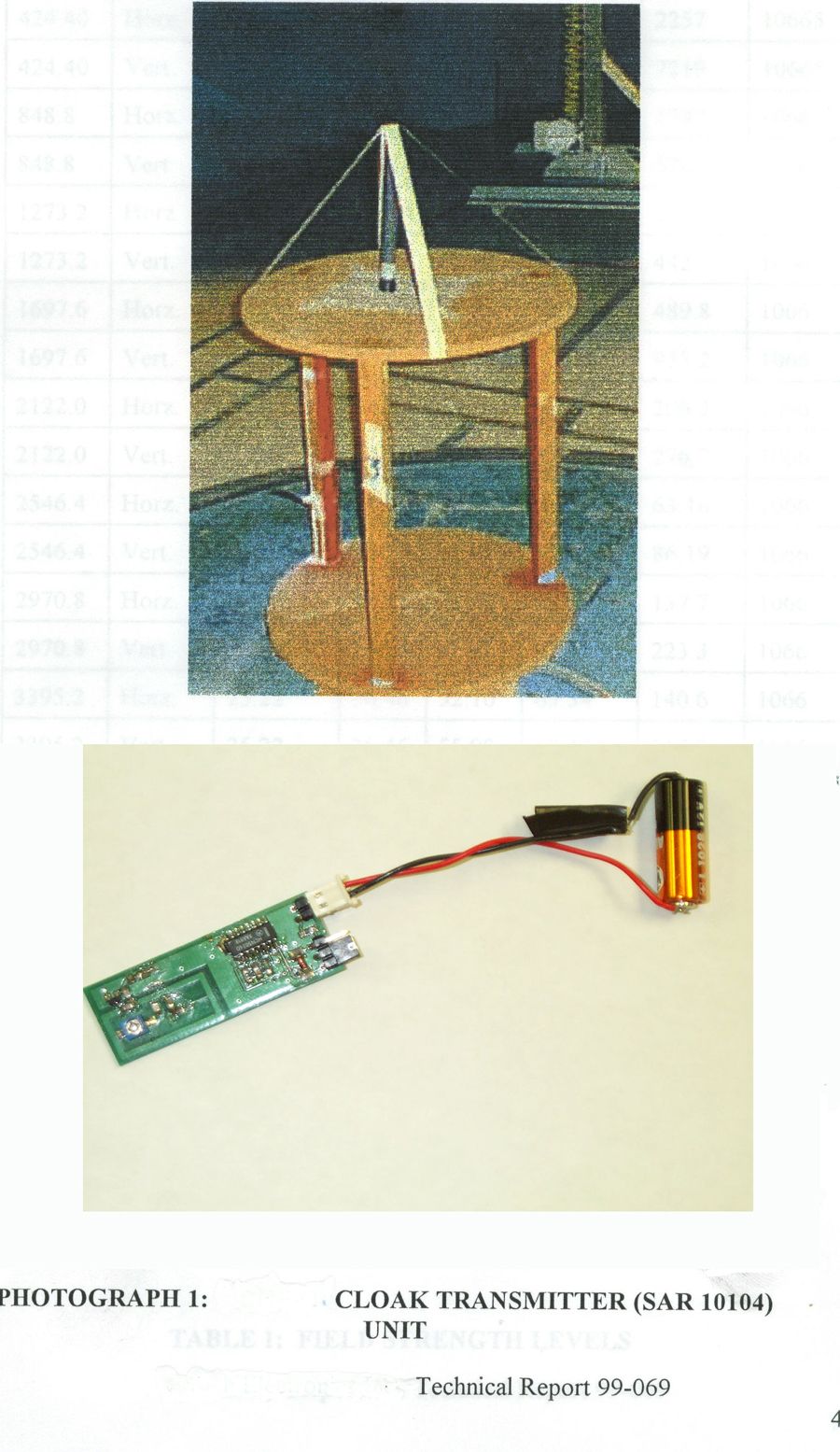
Jan 12, 2000Electronic Cover System TX
Equipment Class
DSC - Part 15 Security/Remote Control Transmitter