OTLM2601ABiomedical Telemetry Transmitter
Agilent Technologies, Inc.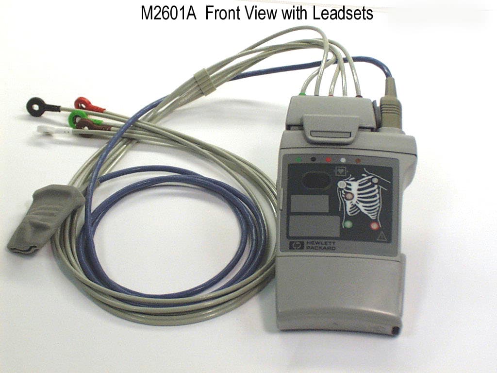
Click to zoom
Application Details
- Equipment Class
- DXX - Part 15 Low Power Communication Device Transmitter
- Date of Grant
- Jan 31, 2000
- Application Purpose
- Original Equipment
- Date of Application
- Nov 30, 1999
- Equipment Note
- Biomedical Telemetry Transmitter
- Frequency Range
- 590.00000000 - 632.00000000
- Company
- Agilent Technologies, Inc.
- Country
- United States
Documents & Files
Document Text
Text extracted from the exhibit documents filed with the FCC. Open a document above to read the original.
Users Manual
HP Telemetry System for the HP Viridia Information Center User Guide Part Number M2600-90201 Printed in the U.S.A. December 1999 Third Edition Copyright © 1999, 1998 by Hewlett-Packard Company. Notice This document contains proprietary information which is protected by copyright. All Rights Reserved. Reproduction, adaptation, or translation without prior written permission is prohibited, except as allowed under the copyright laws. Hewlett-Packard 3000 Minuteman Road Andover, MA 01810-1099 (978) 687-1501 Publication number M2600-90201, Third Edition Printed in USA December 1999 WarrantyThe information contained in this document is subject to change without notice. Hewlett-Packard makes no warranty of any kind with regard to this material, including, but not limited to, the implied warranties or merchantability and fitness for a particular purpose. Hewlett-Packard shall not be liable for errors contained herein or for incidental or consequential damages in connection with the furnishing, performance, or use of this material. Printing History iii Printing History New editions of this document incorporate all material updated since the previous edition. Update packages may be issued between editions and contain replacement and additional pages to be merged by a revision date at the bottom of the page. Pages that are rearranged due to changes on a previous page are not considered revised. The documentation printing date and part number indicate its current edition. The printing date changes when a new edition is printed. (Minor corrections and updates which are incorporated at reprint do not cause the date to change.) The document part number changes when extensive technical changes are incorporated. First Edition............................................................... August 1998 Model M2604A Viridia Mainframe, release D.01/D.02/D.03 Model M2601A Viridia Transmitter, release A.00/A.01/A.02 Model M2605A Viridia Wave Viewer, release A.00/A.01/A.02 Model M1403A Digital UHF Telemetry System with Option C03, release D.01/D.02/D.03 Second Edition............................................................... February 1999 Model M2604A Viridia Mainframe, release D.01/D.02/D.03 Model M2601A Viridia Transmitter, release A.00/A.01/A.02 Model M2605A Viridia Wave Viewer, release A.00/A.01/A.02 Model M1403A Digital UHF Telemetry System with Option C03, release D.01/D.02/D.03 Third Edition............................................................... December 1999 HP Telemetry System, Release B Model M2604A Viridia Mainframe, release D.01/D.02/D.03 Model M2601A Viridia Transmitter, release A.00/A.01/A.02/A.03 Model M2605A Viridia Wave Viewer, release A.00/A.01/A.02 Model M1403A Digital UHF Telemetry System with Option C03, release D.01/D.02/D.03 Details about the specific releases are contained in Appendix C. About this Book iv About this Book This User’s Guide covers the use of the HP Telemetry System with the HP Viridia Information Center. The HP Telemetry System comprises: •HP M2600A Viridia Telemetry System •HP M1403A Digital UHF Telemetry System with Option C03. The User’s Guide contains information on performing day-to-day tasks and troubleshooting common problems as well as detailed information about all clinical applications. It includes lists of alarm and inoperative (INOP) messages, and configuration choices. Your purchased system may not include all the functionality described in this manual. User information for the HP Telemetry System is also contained in the HP Viridia Information Center On-line Help. Help focuses on how to complete basic tasks and troubleshoot problems. Appendix C, “System Releases,” summarizes the differences between the current version of the HP Telemetry System and earlier system releases. THIS GUIDE DOES NOT COVER use of the HP Telemetry System with the HP OmniCare Component Central Monitor. If you are using the HP Telemetry System with the HP OmniCare Component Central Monitor, please refer to the following user documentation •HP Viridia Telemetry System/HP OmniCare Component Central Monitor User’s Guide, order number M2300-91930, publication date 5/97 •HP Viridia Telemetry System User’s Reference Manual, order number M2600-90039, publication date 5/97 •HP Viridia Telemetry System User’s Addendum, order number M2600-90060, publication date 11/97 •HP Viridia Telemetry System User’s Addendum #2, order number M2600-90080, publication date August 1998 •HP Viridia Telemetry System User’s Addendum #3, order number M2600-90099, publication date February 1999 •HP Viridia Telemetry System User Addendum #4, order number M2600-90222, publication date December 1999. About this Book v Document Conventions Procedures Procedures are indicated in text by the heading “Task Summary” followed by the following table: Bold Typeface Objects of actions in procedures appear in bold typeface. Note the following example: Click the Update button. Warnings Warning Warnings are information you should know to avoid injuring patients and personnel. Cautions Caution Cautions are information you should know to avoid damaging your equipment and software. Notes Note—Notes contain additional information on the HP Telemetry System usage. StepAction 1 2 3 HP Telemetry System Warnings vi HP Telemetry System Warnings The warnings and cautions described below refer to the following devices: •HP M2600A Viridia Telemetry System •HP M1403A Digital UHF Telemetry System with Option C03 Warning Do not touch the patient, bed or transmitter during defibrillation. Keep transmitter battery cover closed during defibrillation. Warning Do not install or use power modules for analog output, antennas, and palmtop personal computers (HP Viridia Wave Viewer) within a 2.44 m (8 ft) radius of the patient. Caution Installation and setup must be performed by an HP service representative or designee according to the instructions in HP Viridia Telemetry Installation & Configuration Guide (part number M2600-90036). Contents …
Text truncated - open the document above for the full version.
Attestation Statements
Agilent Technologies, Inc. 3000 Minuteman Road Andover, MA 01810 Gordon Cook Development Engineer Patient Monitoring Division 978 659-3709 telephone 978 685-3577 facsimile [email protected] www.agilent.com January 5, 2000 Federal Communications Commission Office of Engineering & Technology 7435 Oakland Mills Road Columbia, Maryland 21046 Re: FCC ID: OTLM2601A; Confirmation Number: EA96120 Request for confidentiality Agilent Technologies has requested that two exhibits of the referenced application be kept confidential pursuant to CFR 47, Sections .457 and .459. The two exhibits are the schematics and the operational description/block diagram. These contain schematic and operational details of the product for which certification is being sought. This information is labeled as “Company Confidential” and disclosure of these exhibits would potentially be harmful to Agilent Technologies’ business because this product incorporates innovative low- power RF transmitter design techniques, ECG processing technology, and other such details which would be useful to a competitor in the medical telemetry business. This information is not available to the public since all service and repairs are done on a sub- assembly basis and the design details are hidden. It is expected that this information would remain sensitive for at least two years from the date of submission Sincerely, Gordon Cook Development Engineer Patient Monitoring Division Agilent Technologies [email protected]
ID Label/Location Info
Label Description for OTLM2601A Agilent Technologies January, 2000 The FCC ID label will consist of an adhesive backed transparent label material. It will be permanently affixed at the time of manufacture. The letter height is approximately .10 inches, and the letter color is black. The following illustration will show the location and appearance on the rear of the transmitter;
Test Report
This report shall not be reproduced, in whole or in part without the written approval of Test Site Services Inc. This report must not be used by the recipient to claim product endorsement by NVLAP or any other agency of the U.S. Government Test Site Services. Inc. EMI Test Report For Agilent Technologies Viridia Medical Telemetry Transmitter Model M2601A Radiated and Conducted Emissions FCC, Part 15C Test # B90433 Test Site Services, Inc. P.O. Box 766 Marlboro, MA 01752 U.S.A. Phone/Fax: (508) 481-1684 Test Site Services, Inc.Report # B90433 Agilent Technologies11/18/99EUT: Viridia Medical Telemetry Transmitter Table of Contents GENERAL INFORMATION..................................................................................................................................................1 EQUIPMENT UNDER TEST DESCRIPTION.......................................................................................................................3 TEST SUMMARY..................................................................................................................................................................4 BLOCK DIAGRAM...............................................................................................................................................................5 BLOCK DIAGRAM DESCRIPTION......................................................................................................................................6 CABLE DESCRIPTION.........................................................................................................................................................9 SOFTWARE DESCRIPTION................................................................................................................................................10 MODES OF OPERATION.....................................................................................................................................................11 TEST EQUIPMENT LIST.....................................................................................................................................................13 APPENDIX A, TEST DATA................................................................................................................................................A1 APPENDIX B, TEST PHOTOGRAPHS...............................................................................................................................B1 APPENDIX C, TEST PROCEDURES..................................................................................................................................C1 APPENDIX D, MEASUREMENT FACILITIES INFORMATION.......................................................................................D1 Test Site Services, Inc.Report # B90433page 2 of 13 Agilent Technologies11/18/99EUT: Viridia Medical Telemetry Transmitter Administrative Data Regulation : FCC, Part 15C, 15.201b, 15.215, 15.242, Part 2J Per : 15.242c, 15.209, 15.207a Test Method : ANSI C63.4-1992 Test Type : Certification Manufacturer : Agilent Technologies EUT Type/Model # : Viridia Medical Telemetry Transmitter / M2601A Date(s) of Test : 11/18/99 Customer Personnel : Gordon Cook : John Bilodeau Engineer Engineer TSS Personnel : R. WiedemanEMC Engineer : Bob Quinn : Tom Charron Test Engineer Test Engineer Test Location: Open Area Test Site Test Site Services, Inc. 30 Birch St. Milford, MA 01757 U.S.A. NOTICE: FCC Rule 2.955 requires that a Verification Report for a Class A Computing Device must be signed by "an Official of the Company responsible for the device". A signature block has been provided on the first page for this purpose. Test Site Services, Inc.Report # B90433page 3 of 13 Agilent Technologies11/18/99EUT: Viridia Medical Telemetry Transmitter EUT Description The EUT is a (Viridia Medical Telemetry Transmitter) that monitors ECG and SPO 2 patient levels and transmits data to a central receiver system. It operates on specific frequencies from 590 to 632 MHz. Three units were tested at the low, middle and high end of the band (590.0, 611.0, 632.0 MHz.). These units (one at each frequency) were tested simultaneously in close proximity to each other for a worst case test configuration. The units were tested with optional AC adapters. A complete description of the EUT may be found on block identifier page one. The tests were run in a typical configuration including the following support equipment; 1)EUT 1 @ 590.0 MHz.4)(3) SPO 2 Sensors 2)EUT 2 @ 611.0 MHz.5)(3) ECG Leads 3)EUT 3 @ 632.0 MHz.6)(3) AC Adapters REASON FOR TEST Certification per FCC Part 15c, 15.201b, Part 2J CHANGES MADE DURING TEST None DEVIATIONS FROM STANDARD TEST METHOD None Test Site Services, Inc.Report # B90433page 4 of 13 Agilent Technologies11/18/99EUT: Viridia Medical Telemetry Transmitter Test Summary The Viridia Medical Telemetry Transmitter complied with the FCC Part 15 Subpart C Limits for an intentional radiator when tested in the system configuration defined herein. The following table indicates the margins (i.e. difference between measurement point and limit) of the six (6) worst case data points: TEST CLASSMARGIN TO SPEC (db)FREQUENCY (Mhz) (Fundamental Frequencies)-4.6590.0 Per 15.242c-7.9632.0 -8.7611.0 Unwanted Signals-1.81264.00 (including harmonics)-1.92528.00 Per 15.209-2.01896.00 (4.0 MHz. to 6.32 GHz.)-2.11222.00 -2.9569.00 -3.22444.00 Conducted Emissions-20.80.450 Per 15.207a-26.81.380 (120 VAC 60 Hz.)-33.819.210 -35.521.990 -37.826.710 -38.314.930 Test Site Services, Inc.Report # B90433page 5 of 13 Agilent Technologies11/18/99EUT: Viridia Medical Telemetry Transmitter Block Diagram for Viridia Medical Telemetry Transmitter PS = Power Cord Shielded DS = Data Cable Shielded CX = Coaxial CableC1 (DU)C1 (DU)C1 (DU) PU = Power Cord Unshielded DS = Data Cable Shielded FL = Fiber Link = Ferrite Bead = Connector A1 (PU)A2 (PU)A3 (PU) B1 (PU)B2 (PU)B3 (PU) Control Room Ground Plane P/S P/S P/S EUT 1A EUT 1B EUT 1C…
Text truncated - open the document above for the full version.
Contact Information
Applicant
James C Powell(Americas Region Manager - Standards and Regs)
Technical Contact
Non-Technical Contact
Agilent Technologies, Inc.Jonathan Weil
[email protected](978) 659-2913
Test Firm
Test Site Services Co.Lawrence Lee
Technical Specifications
| # | Rule Parts | Frequency Range | Power Output |
|---|---|---|---|
| 1 | 15C | 590 MHz - 632 MHz | - |