OTPGG-03Automotive Immobilizer Remote Control
Shenzhen Shidun Technology Co. LTD.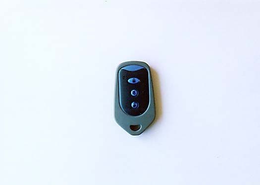
Click to zoom
Application Details
- Equipment Class
- DSC - Part 15 Security/Remote Control Transmitter
- Date of Grant
- Feb 14, 2000
- Application Purpose
- Original Equipment
- Date of Application
- Dec 01, 1999
- Equipment Note
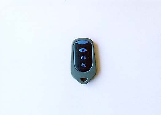
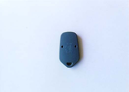
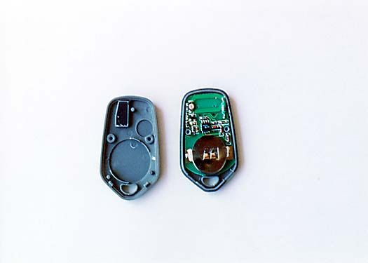
- Automotive Immobilizer Remote Control
- Frequency Range
- 338.00000000 - 338.00000000
- Country
- United States
Documents & Files

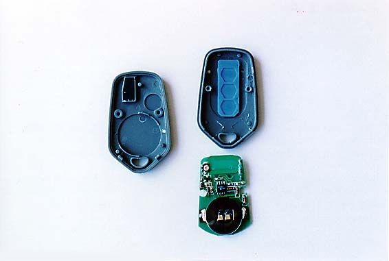
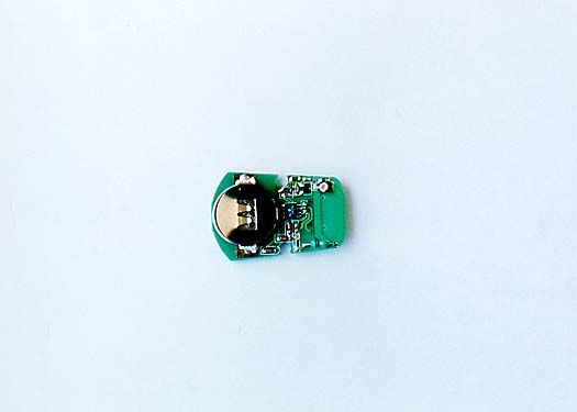
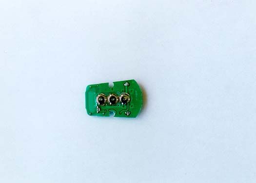
Document Text
Text extracted from the exhibit documents filed with the FCC. Open a document above to read the original.
Users Manual
INSTALATION MANUAL • Installing System Installation has to be carried out by a qualified installer. Please see Diagram 1 for installation detail. Mounting the system Terminal at a place that’s dry and hard to access, and avoiding high tempreture area. The relay should be installed in a place not easily be found. After Installation is completed, carefully check if all the wires are correctly connected before connecting power to main unit. • Installing the Reading Coil Antenna The reading coil antenna has multi layer ring that can be peal off according to the size of the lock cylinder dimension. Place the ring around the lock cylinder. The distance between ring and SHIDUN key should not be more than 3 cm. • Installing The Code Chip Onto The Key Cover Separate the key covers. Trim the key head as needed to fit into key cover glues both sides together. (Hot melt glue is recommended) Terminal Installation Diagram Note: 1. The purple wire should be connected to “ON” of the ignition switch. When the car key turns to “START”, this line should have constant 12V output. 2. As this system has Immobilizer function, the two relays should be installed. 2. The blue wire should be connected to door pin switch. Central door Lock Installation Diagram Diagram 2A Interior System Control principle Diagram 2B Positive /Nagative trigger Diagram 2C Negative Trigger Diagram 2D Positive Trigger Diagram 2E Connecting Diagram for vacuum Lock Type Problem and Dealing Method in system Installation Problemcheck Siren is on1. Checking if the wires are connected correctly as per the installation diagram; 2. If the ignition is in ON position. And the code chip is installed in the key. After installation the Terminal has no response and the remote controller cannot work or cannnot identify the key code 1. Checking if the wires are connected correctly as per the installation diagram; 2. If the fuse of the Terminal power source is burned and find out the reason; 3. If the car battery has enough voltage The key is in ON position and can identify key code,but cannot start the car 1. Check if the relay control wires are correctly connected. The key is in ON position and cannot identify key code the siren stay on. 1. If the readers coil plug is correctly plug in. 2. If the distance between readers coil and key handle exceeding 3cm. 3.If there is any metal between the reader coil and the code chip. After the door is locked, the siren stays on. 1. Check if the door switchs are correctly wire. The remote control distance is too short 1. If the battery voltage is lowered than 4.8V 2. Adjust the location of the receiving antena Manufactured by Shenzhen Fenghongda Investment Co. Ltd Section 15.105(b) of the FCC rules and regulations stipulates the following: For a Class B digital device or peripheral, the instructions furnished by the user shall include the following or similar statement, placed in a prominent location in the text of the manual: FCC Notice This device has been tested and found to comply with the limits for a Class B digital device, pursuant to Part 15 of the FCC Rules. These limits are designed to provide reasonable protection against harmful interference in a residential installation. This device generates, uses, and can radiate radio frequency energy and, if installed and used in accordance with the instruction, may cause harmful interference to radio communications. However, there is no guarantee that interference will not occur in a particular installation. If this device does cause harmful interference to radio or television reception, the user is encouraged to try to correct the interference by one or more of the following measures: • Reorient or relocate the receiving antenna. • Increase the separation between the computer and receiver. • Connect the computer into an outlet on a circuit different from that to which the receiver is connected. • Consult the dealer or an experienced radio/TV technician for help. Caution: Any changes or modifications not expressly approved by the grantee of this device could void the user’s authority to operate the equipment. FCC Compliance Statement This device complies with Part 15 of the FCC Rules. Operation is subject to the following two conditions: (1) This device may not cause harmful interference and (2) this device must accept any interference received, including interference that may cause undesired operation .
Block Diagram
Remotecontroller F=338.80 MHz receiver MCU F=125kHz Controlunit ReaderCircuit Transponder 1 2 34 A BC D 4 3 2 1 D CB A Title Number Revision Size A4 Date: 9-Nov-1999 Sheet of File: A:\Power.sch Drawn By: Vin 1 GND 2 Vout 3 U57808 Vin 1 GND 2 Vout 3 U678L05 D11 IN4007 EC1 470uF/25V C2104 SMD EC2 470uF/25V C1 104 SMD L110uH EC3 220uF/25V C3103 SMD EC4470uF/16V C4104 SMD 12V 8V 5V CON1 1 EC5 100uF/50V power supplyInput voltage is 12v. It is changed to 8v by U5.After U6, it is changed to 5v. 1 2 34 A BC D 4 3 2 1 D CB A Title Number Revision Size A4 Date: 9-Nov-1999 Sheet of File: A:\Re ad_cod.sch Dra wn By : OUTPUT 2 /OE 3 INPUT 4 MS 5 CFE 6 DGND 7 COI L2 8 GND 1 COI L1 9 VEXT 10 DVS 11 VBATT 12 STBY 13 VS 14 RF 15 HIPAS 16 U1U2270B C19104 R3543K R3668K 5V 8V RB3RB1 R3310K 5V C30472 K6RL11-12V K7RL11-12V K4RL11-12V K5RL11-12V C21302C20302 C27 821*2 C26 821*2 C28 681*2 C29 681*2 C23681C22681 C25301C24301 12V CON5(3) D8 IN4148 D10 IN4148 D9 IN4148 D5 IN4148 R2975K R28100K D7IN4148D6IN4148 CON5(1) Q8 9013 R39 10K CONN1CONN2CONN3CONN4 C17473 C1 6 473 R32 470K C14332C15332 R31 4.7K This is rea This is reader system.The U2270B enables a MCU to read and to process the identifier or the key code from a transponder.K4, K5, K6, and K7 are used for resonant frequencies.CON5 (3), CON5 (1) is connected to pickup coil.PORT (RB3) output Manchester code.PORT (RB1) enable U2270B.CONN1, CONN2, CONN3, CONN4, it controls K4, K5, K6, K7. 1 2 3 4 4 3 2 1 D CB A TOCK 1 VDD 2 NC 3 VSS 4 NC 5 RA0 6 RA1 7 RA2 8 RA3 9 RB0 10 RB1 11 RB2 12 RB3 13 RB4 14 RB5 15 RB6 16 RB7 17 RC0 18 RC1 19 RC2 20 RC3 21 RC4 22 RC5 23 RC6 24 RC7 25 OSC2 26 OSC1 27 MCLR 28 U2PIC16C57 VCC 8 NC 7 NC 6 GND 5 DO 4 DI 3 SK 2 CS 1 U393C46B C12102 C13102 5V Q42SA1162 R110K R1647KR17270K R1833K X14MHz R191M C922PC1022P 12 3 U15A 4001 56 4 U15B 4001 89 10 U15C 4001 1213 11 U15D 4001 IN2 2 IN3 3 IN4 4 IN5 5 IN6 6 IN7 7 GND 8 VCC 9 OUT7 10 OUT6 11 OUT5 12 OUT4 13 OUT3 14 OUT2 15 OUT1 16 IN1 1 U16MC1413 BZ BUZZER Q19013 R610k 8v K1RL11-12VK2RL11-12VK3RL11-12V K4RL11-12V RL2RL11-12VRL3RL11-12V 12v R13SPEAKER PortPortPortPortPortPort PortPort D12IN4007 CON(11) Q59013 Q7B772 R3410K R384.7K R3747K Q2 9013 Q3 9013 Q6 B772 R15 10K R54.7K R247K D1 IN4148 D14IN4007 R3 R4. 7K D2 IN4148 D13 IN4007 D3IN4148 R44.7K R1447K R1333K R2727K C8104 D4IN4148 CON4(3) R10 10K R94.7K C6104 R114.7K R810K R124.7K CON3(2) 12V R710K C5 104 R2610K R2510K C11104 CON3(4) R2468K R2327K EC61uF/50V CON3(5) RFI N CON3(2) R301K R20RES1 SW1SW- P B R2010K 5V CON3( 3) CON1(8) CON1(10) CONN1 CONN4CONN3CONN2 RB1RB3 5v PIC16C57 (U2) is a microcontroller.It decodes code hopping and Manchester code93C46B(U3) is an eeprom.It stored the serial number, synchronization information and decryption key.CON3 detect the ignition. CON3 detect the brake light input for locking doorsCON3 detect the door state (lock or unlock).SW1 learning button.Q2, Q6 controls lock circuit.CON4 connect with shock sensor.CON3 connect with an LED, it indicate the system enter armed state or learn state.Q5, Q7 connect with an alarm speaker.K1 trunk release outputrelay. K2, K3 door lock and unlock relaysK4 flashing lights relay
Cover Letter(s)
May 10, 2001 Federal Communications Commission 7435 Oakland Mills Road Columbia, MD 21046 We the undersigned, hereby certify that, in the case of individual applicant, he or she is not subject to a denial of federal benefits pursuant to section 5301 of the Anti-Drug Abuse Act of 1988, 21 USC 853a or in the case of non-individual applicant (e.g. corporation, partnership or other unincorporated association), no party to the applicant is subject to adenial of federal benefit pursuant to that action. Sincerely, John Lee Manager Shenzhen Shidun Technology Co. LTD. 2030 N Del Mar Ave Rosemead Ca, 91770
ID Label/Location Info
4 ¾” 21727 3 ½” MAIN UNIT BOX BOTTOM VIEW 1 1/8” 2 3/8” BOTTOM OF UNIT Model # GG-03 Serial # xxxxxxxx FCC ID: OTPGG-03
Operational Description
System operation The system can only be operated with SHIDUN Automobile Key (with code chip) Before starting, the ignition relay and the fuel pump relay are in off position. When the key is turn to ON position, the Immobilizer will attempt to read the code chip on the key if the code is correct the system will beep twice, showing that the system is deactived. Remote Control of Door Lock Press the lock button on the remote controller, the system will immediately lock the door and the siren beep once and the light flash one time. The car will enter the state of alert. Press the open button on the remote controller, the system will immediately open the door and the siren beep two times, the car light flash two times. The remote control anti- theft system is then disarmed. The car can only be started with SHIDUN key. Searching Press the Lock button on the controller twice, the system will start searching .The Siren will beep eight times and meanwhile the car light will flash. Mute Sound Press the Mute Button on the controller before remote searching opening or locking the door, the siren will remain silent and the car lights flashing when the alarm system is in working condition. Code-hopping Remote Controller Learning If the Remote Controller is missing, the missing Remote Controller code can be cleared off from the alarm, and meanwhile the alarm can learn the new code on another remote controller. The method is to open the alarm and press the Learning Button on the alarm the Alert Indicating Light will flash. Then the Indicating Light will stop flashing. Then press any of the buttons on the Remote Controller twice which indicating that the Remote Controller has completed learning and can be operated normally. Automaticaly door Locking The door will be automaticaly locked when the brake is applied after the car is started. If you want to open the door when in driving, just use the remote controller. Specifications: Main Unit Power supply: 12V +/-2V Static Current: 20mA Central Door Lock Output: 10A Control current (for fuel pipe and electric circuit): 20A RFID Frequency: 125KHz Remote Controller: Transmitting Frequency: 310MHz-350MHz RF watt: .001 mW Power supply: 6V Static Current: 0mA Transmitting Current: 3mA Battery Type: CR2016 x 2
Operational Description
System operation The system can only be operated with SHIDUN Automobile Key (with code chip) Before starting, the ignition relay and the fuel pump relay are in off position. When the key is turn to ON position, the Immobilizer will attempt to read the code chip on the key if the code is correct the system will beep twice, showing that the system is deactived. Remote Control of Door Lock Press the lock button on the remote controller, the system will immediately lock the door and the siren beep once and the light flash one time. The car will enter the state of alert. Press the open button on the remote controller, the system will immediately open the door and the siren beep two times, the car light flash two times. The remote control anti- theft system is then disarmed. The car can only be started with SHIDUN key. Searching Press the Lock button on the controller twice, the system will start searching .The Siren will beep eight times and meanwhile the car light will flash. Mute Sound Press the Mute Button on the controller before remote searching opening or locking the door, the siren will remain silent and the car lights flashing when the alarm system is in working condition. Code-hopping Remote Controller Learning If the Remote Controller is missing, the missing Remote Controller code can be cleared off from the alarm, and meanwhile the alarm can learn the new code on another remote controller. The method is to open the alarm and press the Learning Button on the alarm the Alert Indicating Light will flash. Then the Indicating Light will stop flashing. Then press any of the buttons on the Remote Controller twice which indicating that the Remote Controller has completed learning and can be operated normally. Automaticaly door Locking The door will be automaticaly locked when the brake is applied after the car is started. If you want to open the door when in driving, just use the remote controller. Specifications: Main Unit Power supply: 12V +/-2V Static Current: 20mA Central Door Lock Output: 10A Control current (for fuel pipe and electric circuit): 20A RFID Frequency: 125KHz Remote Controller: Transmitting Frequency: 338MHz RF watt: .001 mW Power supply: 6V Static Current: 0mA Transmitting Current: 3mA Battery Type: CR2016 x 2
Schematics
Remotecontroller F=338.80 MHz receiver MCU F=125kHz Controlunit ReaderCircuit Transponder 1 2 34 A BC D 4 3 2 1 D CB A Title Number Revision Size A4 Date: 9-Nov-1999 Sheet of File: A:\Power.sch Drawn By: Vin 1 GND 2 Vout 3 U57808 Vin 1 GND 2 Vout 3 U678L05 D11 IN4007 EC1 470uF/25V C2104 SMD EC2 470uF/25V C1 104 SMD L110uH EC3 220uF/25V C3103 SMD EC4470uF/16V C4104 SMD 12V 8V 5V CON1 1 EC5 100uF/50V power supplyInput voltage is 12v. It is changed to 8v by U5.After U6, it is changed to 5v. 1 2 34 A BC D 4 3 2 1 D CB A Title Number Revision Size A4 Date: 9-Nov-1999 Sheet of File: A:\Re ad_cod.sch Dra wn By : OUTPUT 2 /OE 3 INPUT 4 MS 5 CFE 6 DGND 7 COI L2 8 GND 1 COI L1 9 VEXT 10 DVS 11 VBATT 12 STBY 13 VS 14 RF 15 HIPAS 16 U1U2270B C19104 R3543K R3668K 5V 8V RB3RB1 R3310K 5V C30472 K6RL11-12V K7RL11-12V K4RL11-12V K5RL11-12V C21302C20302 C27 821*2 C26 821*2 C28 681*2 C29 681*2 C23681C22681 C25301C24301 12V CON5(3) D8 IN4148 D10 IN4148 D9 IN4148 D5 IN4148 R2975K R28100K D7IN4148D6IN4148 CON5(1) Q8 9013 R39 10K CONN1CONN2CONN3CONN4 C17473 C1 6 473 R32 470K C14332C15332 R31 4.7K This is rea This is reader system.The U2270B enables a MCU to read and to process the identifier or the key code from a transponder.K4, K5, K6, and K7 are used for resonant frequencies.CON5 (3), CON5 (1) is connected to pickup coil.PORT (RB3) output Manchester code.PORT (RB1) enable U2270B.CONN1, CONN2, CONN3, CONN4, it controls K4, K5, K6, K7. 1 2 3 4 4 3 2 1 D CB A TOCK 1 VDD 2 NC 3 VSS 4 NC 5 RA0 6 RA1 7 RA2 8 RA3 9 RB0 10 RB1 11 RB2 12 RB3 13 RB4 14 RB5 15 RB6 16 RB7 17 RC0 18 RC1 19 RC2 20 RC3 21 RC4 22 RC5 23 RC6 24 RC7 25 OSC2 26 OSC1 27 MCLR 28 U2PIC16C57 VCC 8 NC 7 NC 6 GND 5 DO 4 DI 3 SK 2 CS 1 U393C46B C12102 C13102 5V Q42SA1162 R110K R1647KR17270K R1833K X14MHz R191M C922PC1022P 12 3 U15A 4001 56 4 U15B 4001 89 10 U15C 4001 1213 11 U15D 4001 IN2 2 IN3 3 IN4 4 IN5 5 IN6 6 IN7 7 GND 8 VCC 9 OUT7 10 OUT6 11 OUT5 12 OUT4 13 OUT3 14 OUT2 15 OUT1 16 IN1 1 U16MC1413 BZ BUZZER Q19013 R610k 8v K1RL11-12VK2RL11-12VK3RL11-12V K4RL11-12V RL2RL11-12VRL3RL11-12V 12v R13SPEAKER PortPortPortPortPortPort PortPort D12IN4007 CON(11) Q59013 Q7B772 R3410K R384.7K R3747K Q2 9013 Q3 9013 Q6 B772 R15 10K R54.7K R247K D1 IN4148 D14IN4007 R3 R4. 7K D2 IN4148 D13 IN4007 D3IN4148 R44.7K R1447K R1333K R2727K C8104 D4IN4148 CON4(3) R10 10K R94.7K C6104 R114.7K R810K R124.7K CON3(2) 12V R710K C5 104 R2610K R2510K C11104 CON3(4) R2468K R2327K EC61uF/50V CON3(5) RFI N CON3(2) R301K R20RES1 SW1SW- P B R2010K 5V CON3( 3) CON1(8) CON1(10) CONN1 CONN4CONN3CONN2 RB1RB3 5v PIC16C57 (U2) is a microcontroller.It decodes code hopping and Manchester code93C46B(U3) is an eeprom.It stored the serial number, synchronization information and decryption key.CON3 detect the ignition. CON3 detect the brake light input for locking doorsCON3 detect the door state (lock or unlock).SW1 learning button.Q2, Q6 controls lock circuit.CON4 connect with shock sensor.CON3 connect with an LED, it indicate the system enter armed state or learn state.Q5, Q7 connect with an alarm speaker.K1 trunk release outputrelay. K2, K3 door lock and unlock relaysK4 flashing lights relay
Test Report
Page 1 of 28 Report No: FC99-031 CERTIFICATION TEST REPORT FOR THE IMMOBILIZER FOR AUTOMOTIVE, GG-03 FCC PART 15 SUBPART C COMPLIANCE DATE OF ISSUE: SEPTEMBER 23, 1999 PREPARED FOR: Shenzhen Shidun Technology Co., LTD. 24/F.B Yongfu Guoqi Building Shangbu South Road She Shenzhen, China 518030 P.O. No: W.O. No: 71772 PREPARED BY: Joyce Walker CKC Laboratories, Inc. 5473A Clouds Rest Mariposa, CA 95338 Date of test: August 27, 1999 Report No: FC99-031 DOCUMENTATION CONTROL: _____________________________ Tracy Phillips Documentation Control Supervisor CKC Laboratories, Inc. APPROVED BY: _____________________________ Dennis Ward Director of Laboratories CKC Laboratories, Inc. This report contains a total of 28 pages and may be reproduced in full only. Partial reproduction may only be done with the written consent of CKC Laboratories, Inc. Page 2 of 28 Report No: FC99-031 TABLE OF CONTENTS Administrative Information ............................................................................................. 3 Summary Of Results........................................................................................................ 4 Equipment Under Test (EUT) Description...................................................................... 4 Measurement Uncertainty................................................................................................ 4 EUT Operating Frequency............................................................................................... 4 Peripheral Devices ........................................................................................................... 4 Report Of Measurements................................................................................................. 5 Table 1: Fundamental Radiated Emission Levels .............................................. 5 Table 2: Spurious Emission Levels - Less Than 1 GHz..................................... 6 Table 3: Six Highest Spurious Emission Levels - Greater Than 1 GHz ............ 7 Table A : List Of Test Equipment ................................................................................... 8 EUT Setup .......................................................................................................................9 Test Instrumentation And Analyzer Settings................................................................... 9 Table B : Analyzer Bandwidth Settings Per Frequency Range........................... 9 Spectrum Analyzer Detector Functions............................................................... 10 Peak ......................................................................................................... 10 Quasi-Peak............................................................................................... 10 Average.................................................................................................... 10 Test Methods ...................................................................................................................11 Radiated Emissions Testing................................................................................. 11 Occupied Bandwidth ........................................................................................... 12 Sample Calculations ........................................................................................................ 12 Appendix A : Information About The Equipment Under Test........................................ 13 I/O Ports............................................................................................................... 14 Crystal Oscillators ............................................................................................... 14 Printed Circuit Boards ......................................................................................... 14 Required EUT Changes To Comply.................................................................... 14 Cable Information................................................................................................ 14 Photograph Showing Radiated Emissions ........................................................... 15 Photograph Showing Radiated Emissions ........................................................... 16 Appendix B : Measurement Data Sheets ......................................................................... 17 Occupied Bandwidth Plot.................................................................................... 18 Occupied Bandwidth Plot.................................................................................... 19 Duty Cycle Plot ................................................................................................... 20 Duty Cycle Plot ................................................................................................... 21 Duty Cycle Plot ................................................................................................... 22 Duty Cycle Plot ................................................................................................... 23 Duty Cycle Plot ................................................................................................... 24 Page 3 of 28 Report No: FC99-031 CKC Laboratories, Inc. has Certificates of Accreditation from the following agencies : DATech (Germany); A2LA (USA); FCC (USA); VCCI (Japan); BSMI (Taiwan); HOKLAS (Hong Kong). CKC Laboratories, Inc. has Letters of Acceptance through an MRA for the following agencies: ACA/NATA (Australia); SABS (South Africa); SWEDAC (Sweden); TUV Rheinland-Germany; TUV Rheinland- Korea; TUV Rheinland-Russia; Radio Communications Agency (RA); NEMKO (Norway). ADMINISTRATIVE INFORMATION DATE OF TEST: August 27, 1999 PURPOSE OF TEST: To demonstrate the compliance of the Immobilizer for Automotive, GG-03, with the requirements for FCC Part 15 Subpart C devices. MANUFACTURER: Shenzhen Shidun Technology Co., LTD. 24/F.B Yongfu Guoqi Building Shangbu South Road She Shenzhen, China …
Text truncated - open the document above for the full version.
Contact Information
Applicant
John Lee(Manager)
Technical Contact
CKC Laboratories, Inc.Tracy Phillips
[email protected]1-800-500-4362
5473A Clouds Rest · Mariposa, California · United States
Non-Technical Contact
CKC Laboratories, Inc.Joyce Walker
[email protected]1-800-500-4362
Test Firm
CKC Laboratories, Inc.Steve Behm
Technical Specifications
| # | Rule Parts | Frequency Range | Power Output |
|---|---|---|---|
| 1 | 15C | 338 MHz - 338 MHz | - |