OTQEASCAP/EAS Encoder-Decoder
EZ Automation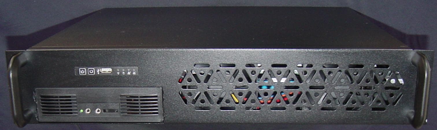
Click to zoom
Application Details
- Equipment Class
- EAD - Part 11 Emergency Alert Devices
- Date of Grant
- Jul 08, 2013
- Application Purpose
- Original Equipment
- Date of Application
- Aug 19, 2012
- Equipment Note
- CAP/EAS Encoder-Decoder
- Company
- EZ Automation
- Country
- United States
Documents & Files
Document Text
Text extracted from the exhibit documents filed with the FCC. Open a document above to read the original.
Users Manual
FCC Part 15 Notice: Note: This equipment has been tested and found to comply with the limits for a Class B digital device, pursuant to part 15 of the FCC Rules. These limits are designed to provide reasonable protection against harmful interference in a residential installation. This equipment generates, uses and can radiate radio frequency energy and, if not installed and used in accordance with the instructions, may cause harmful interference to radio communications. However, there is no guarantee that interference will not occur in a particular installation. If this equipment does cause harmful interference to radio or television reception, which can be determined by turning the equipment off and on, the user is encouraged to try to correct the interference by one or more of the following measures: —Reorient or relocate the receiving antenna. —Increase the separation between the equipment and receiver. —Connect the equipment into an outlet on a circuit different from that to which the receiver is connected. —Consult the dealer or an experienced radio/TV technician for help. Special Instructions: Shielded interconnect cables and a shielded AC power cable must be employed with this equipment to ensure compliance with the pertinent RF emission limits governing this device. Changes or modifications not expressly approved by the system’s manufacturer could void the user’s authority to operate the equipment. Assembled From Tested Components by: EZ Automation 3302 N. Van Dyke Rd. Imlay City, MI 48444 (810) 895-2040 www.voicetracking.com Product Name EZ Automation Product Model EAS EZ Automation EAS/CAP Encoder Decoder www.voicetracking.com (810) 895-2040 © 2005-2012 GETTING STARTED PROGRAMMING: OVERVIEW: This section will take you step by step through the programming setup process to get your EAS system programmed and running. This initial setup should be performed by or at least with the assistance of your Engineering department. It is important that the initial programming is done properly. PART 1: SYSTEM SETUP. STEP 1: GETTING TO THE STATION SETUP SCREEN. The first step is configuring the EAS unit. To enter the setup, go to the menu bar click on Config, then on Station Setup. This will take you to the station setup screen. . STEP 2: Identifier. Enter the station callsign in the upper left field. This must be 8 characters long. Fill any unused spaces with slashes "/" (required). STEP 3: Input Alias(s). Fill in the sources name you are receiving on the analog inputs. This step is optional but is recommended. STEP 4: Message Timeout. This is the recording timeout in seconds for received EAS messages (required). 120 seconds is typical. STEP 5: UTC Comp. This is the difference between universal time and your time zone in hours (required). STEP 6: Home FIPS. This is your home county (required). This the state code plus county code. Example: Say a station is licensed to New York, New York....New York's state code is 36. New York's county code is 061. So the code is 0+36+061 or 036061. A list of FIPS codes is available at this website: http://www.epa.gov/enviro/html/codes/state.html You may also obtain your county code from PART 2 on the next page. STEP 7: EAS Originator Code. This is a three-letter code assigned to the type of facility (required). A broadcast station would use EAS. The National Weather service uses NWS. Other government agencies use CIV. STEP 8: 2-Tone Length. This is the length in seconds of the two-tone attention signal (850Hz and 953 Hz) transmitted during alerts. At the time of this writing, 8 seconds is required. PART 2: COUNTY SETUP. STEP 1: GETTING TO THE EVENT/FIPS SETUP SCREEN. This is the second part is configuring the EAS unit. To enter the setup, go to the menu bar click on Config, then on Event/FIPS Setup. This will take you to the setup screen (see picture below). You will first want to adjust the priority of the Event Codes (optional). This is done on the right-hand pane. Click on the item(s) you want to adjust so it is highlighted in blue, select the Priority from the drop-down, and then press Change Priority of Selected. For example in most areas, a Tornado Warning would be second-highest priority after a national level emergency (EAN) which is a 1 priority. We suggest setting TOR (Tornado Warning) to a priority of 2. A priority of 0 means no automatic action will be taken, but it will be logged. STEP 2: Adding Counties to Event Codes. In this step you must highlight the Event/Priority codes on the right that you want your system to respond to (you may hold CTRL key to select multiple one, and/or you may drag to select all of them. Next, on the upper left, select a State and then select a County in your coverage area. Lastly, press the Add County Code + Event Code + Priority button to add them to the list on the lower left (see picture below). You will need to change the county and press the Add button for all counties in your service area. Congratulations! You have completed the software setup part of the instructions. Your system is almost ready to be put into operation. Audio Wiring: Note: Static Sensitivity: Some of the devices contained in unit are susceptible to static discharges. Appropriate static control procedures should be employed at all times when servicing. All devices connected to the unit should be grounded. For example, a properly grounded three-prong outlet is probably acceptable. In the event that the device does not have a proper grounding plug, a #12 or #14 stranded grounding wire should be added to the device in a “star” configuration. Many stations neglect to connect their satellite receivers, dishes, cable modems, DSL lines and etc to a common ground system. Because of the potential for lightning damage, all of the devices really need to be connected to a “star-type” common ground. In addition, a UPS with power, telephone, antenna, and Ethernet protection is strongly urged. Installation: The basic components of installation are the Audio …
Text truncated - open the document above for the full version.
Users Manual
FCC Part 15 Notice: Note: This equipment has been tested and found to comply with the limits for a Class B digital device, pursuant to part 15 of the FCC Rules. These limits are designed to provide reasonable protection against harmful interference in a residential installation. This equipment generates, uses and can radiate radio frequency energy and, if not installed and used in accordance with the instructions, may cause harmful interference to radio communications. However, there is no guarantee that interference will not occur in a particular installation. If this equipment does cause harmful interference to radio or television reception, which can be determined by turning the equipment off and on, the user is encouraged to try to correct the interference by one or more of the following measures: —Reorient or relocate the receiving antenna. —Increase the separation between the equipment and receiver. —Connect the equipment into an outlet on a circuit different from that to which the receiver is connected. —Consult the dealer or an experienced radio/TV technician for help. Special Instructions: Shielded interconnect cables and a shielded AC power cable must be employed with this equipment to ensure compliance with the pertinent RF emission limits governing this device. Changes or modifications not expressly approved by the system’s manufacturer could void the user’s authority to operate the equipment. Assembled From Tested Components by: EZ Automation 3302 N. Van Dyke Rd. Imlay City, MI 48444 (810) 895-2040 www.voicetracking.com Product Name EZ Automation Product Model EAS EZ Automation EAS/CAP Encoder Decoder www.voicetracking.com (810) 895-2040 © 2005-2012 GETTING STARTED PROGRAMMING: OVERVIEW: This section will take you step by step through the programming setup process to get your EAS system programmed and running. This initial setup should be performed by or at least with the assistance of your Engineering department. It is important that the initial programming is done properly. PART 1: SYSTEM SETUP. STEP 1: GETTING TO THE STATION SETUP SCREEN. The first step is configuring the EAS unit. To enter the setup, go to the menu bar click on Config, then on Station Setup. This will take you to the station setup screen. . STEP 2: Identifier. Enter the station callsign in the upper left field. This must be 8 characters long. Fill any unused spaces with slashes "/" (required). STEP 3: Input Alias(s). Fill in the sources name you are receiving on the analog inputs. This step is optional but is recommended. STEP 4: Message Timeout. This is the recording timeout in seconds for received EAS messages (required). 120 seconds is typical. STEP 5: UTC Comp. This is the difference between universal time and your time zone in hours (required). STEP 6: Home FIPS. This is your home county (required). This the state code plus county code. Example: Say a station is licensed to New York, New York....New York's state code is 36. New York's county code is 061. So the code is 0+36+061 or 036061. A list of FIPS codes is available at this website: http://www.epa.gov/enviro/html/codes/state.html You may also obtain your county code from PART 2 on the next page. STEP 7: EAS Originator Code. This is a three-letter code assigned to the type of facility (required). A broadcast station would use EAS. The National Weather service uses NWS. Other government agencies use CIV. STEP 8: 2-Tone Length. This is the length in seconds of the two-tone attention signal (850Hz and 953 Hz) transmitted during alerts. At the time of this writing, 8 seconds is required. PART 2: COUNTY SETUP. STEP 1: GETTING TO THE EVENT/FIPS SETUP SCREEN. This is the second part is configuring the EAS unit. To enter the setup, go to the menu bar click on Config, then on Event/FIPS Setup. This will take you to the setup screen (see picture below). You will first want to adjust the priority of the Event Codes (optional). This is done on the right-hand pane. Click on the item(s) you want to adjust so it is highlighted in blue, select the Priority from the drop-down, and then press Change Priority of Selected. For example in most areas, a Tornado Warning would be second-highest priority after a national level emergency (EAN) which is a 1 priority. We suggest setting TOR (Tornado Warning) to a priority of 2. A priority of 0 means no automatic action will be taken, but it will be logged. STEP 2: Adding Counties to Event Codes. In this step you must highlight the Event/Priority codes on the right that you want your system to respond to (you may hold CTRL key to select multiple one, and/or you may drag to select all of them. Next, on the upper left, select a State and then select a County in your coverage area. Lastly, press the Add County Code + Event Code + Priority button to add them to the list on the lower left (see picture below). You will need to change the county and press the Add button for all counties in your service area. Congratulations! You have completed the software setup part of the instructions. Your system is almost ready to be put into operation. Audio Wiring: Note: Static Sensitivity: Some of the devices contained in unit are susceptible to static discharges. Appropriate static control procedures should be employed at all times when servicing. All devices connected to the unit should be grounded. For example, a properly grounded three-prong outlet is probably acceptable. In the event that the device does not have a proper grounding plug, a #12 or #14 stranded grounding wire should be added to the device in a “star” configuration. Many stations neglect to connect their satellite receivers, dishes, cable modems, DSL lines and etc to a common ground system. Because of the potential for lightning damage, all of the devices really need to be connected to a “star-type” common ground. In addition, a UPS with power, telephone, antenna, and Ethernet protection is strongly urged. Installation: The basic components of installation are the Audio …
Text truncated - open the document above for the full version.
Operational Description
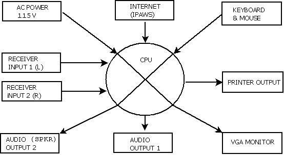
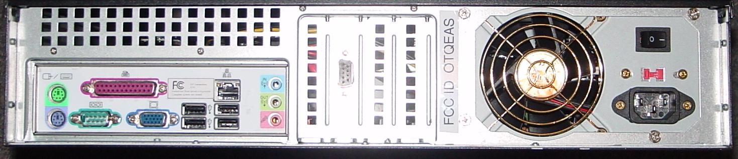
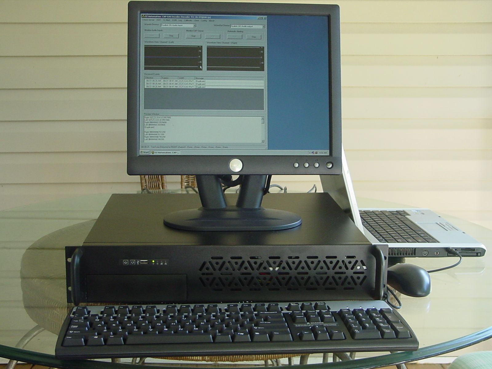
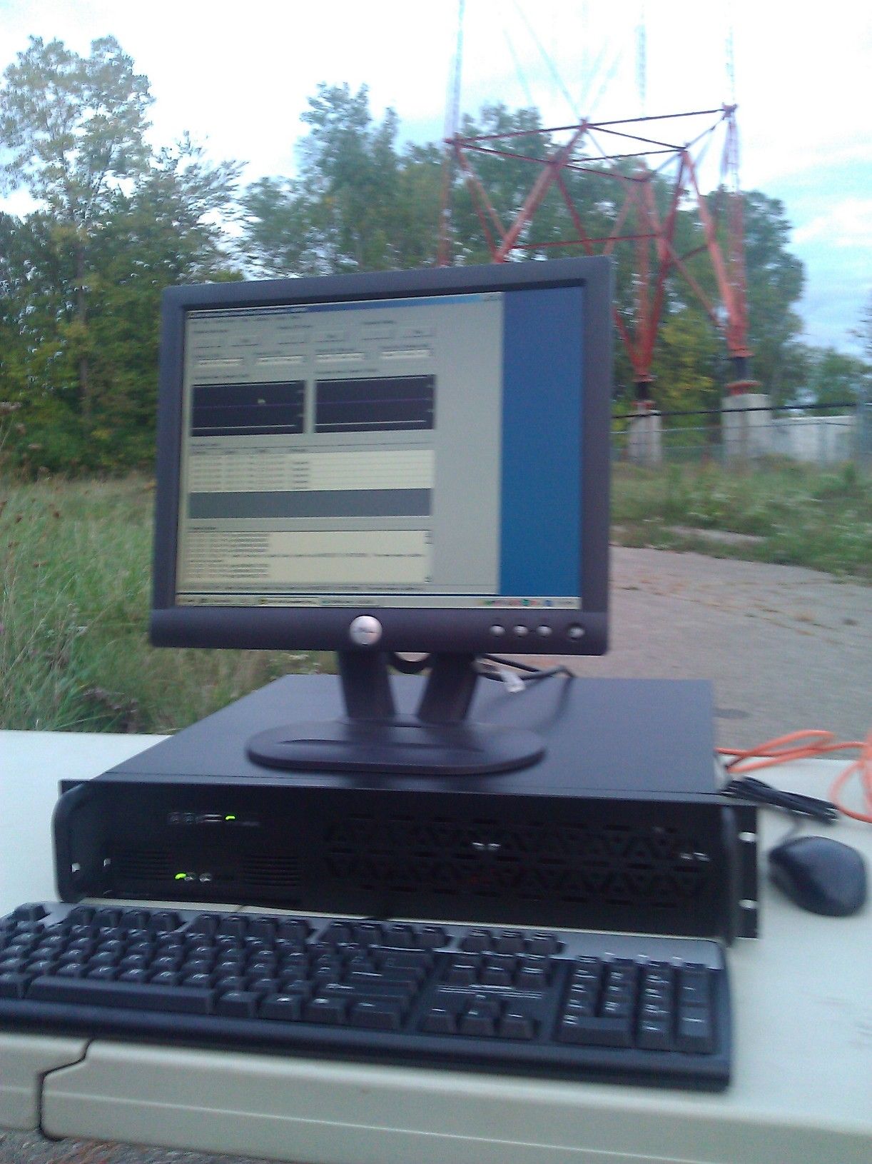
EZ Automation CAP/EAS Encoder Decoder www.voicetracking.com (810) 895-2040 © 2005-2012 OPERATIONAL DESCRIPTION: The unit provides the features of an EAS encoder and decoder, as well as built-in CAP to EAS conversion. This makes the unit capable of handling all EAS needs as a single solution under part 11 of the FCC rules. The EAS inputs are capable of decoding SAME messages from analog inputs, as well as recording and storing audio for as long as needed. The unit is capable of encoding SAME messages to function as an EAS encoder via the audio output. The built-in CAP-to EAS converter is capable of converting and formatting CAP message into EAS messages, including text to speech. The Text to Speech can be "trained" to correct pronunciations. The internet connection is made through a standard RJ-45 Ethernet connection. The unit has two standard serial connections, as well as several USB serial connections, and a parallel port connection. A visual display is provided on a standard VGA monitor, and human input is available on a standard QWERY keyboard and mouse. AC power is set to 115V 60 Hz by the Factory. All message processing is done with a multi-core Intel processor operating on the Windows operating system and custom software. EZ Automation 3302 N. Van Dyke Imlay City, MI 48444 (810) 895-2040 www.voicetracking.com
Operational Description
EZ Automation CAP/EAS Encoder Decoder www.voicetracking.com (810) 895-2040 © 2005-2012 OPERATIONAL DESCRIPTION: The unit provides the features of an EAS encoder and decoder, as well as built-in CAP to EAS conversion. This makes the unit capable of handling all EAS needs as a single solution under part 11 of the FCC rules. The EAS inputs are capable of decoding SAME messages from analog inputs, as well as recording and storing audio for as long as needed. The unit is capable of encoding SAME messages to function as an EAS encoder via the audio output. The built-in CAP-to EAS converter is capable of converting and formatting CAP message into EAS messages, including text to speech. The Text to Speech can be "trained" to correct pronunciations. The internet connection is made through a standard RJ-45 Ethernet connection. The unit has two standard serial connections, as well as several USB serial connections, and a parallel port connection. A visual display is provided on a standard VGA monitor, and human input is available on a standard QWERY keyboard and mouse. AC power is set to 115V 60 Hz by the Factory. All message processing is done with a multi-core Intel processor operating on the Windows operating system and custom software. Submitted by: Edward T. Czelada February 1st, 2013 EZ Automation 3302 N. Van Dyke Imlay City, MI 48444 (810) 895-2040 www.voicetracking.com
Schematics
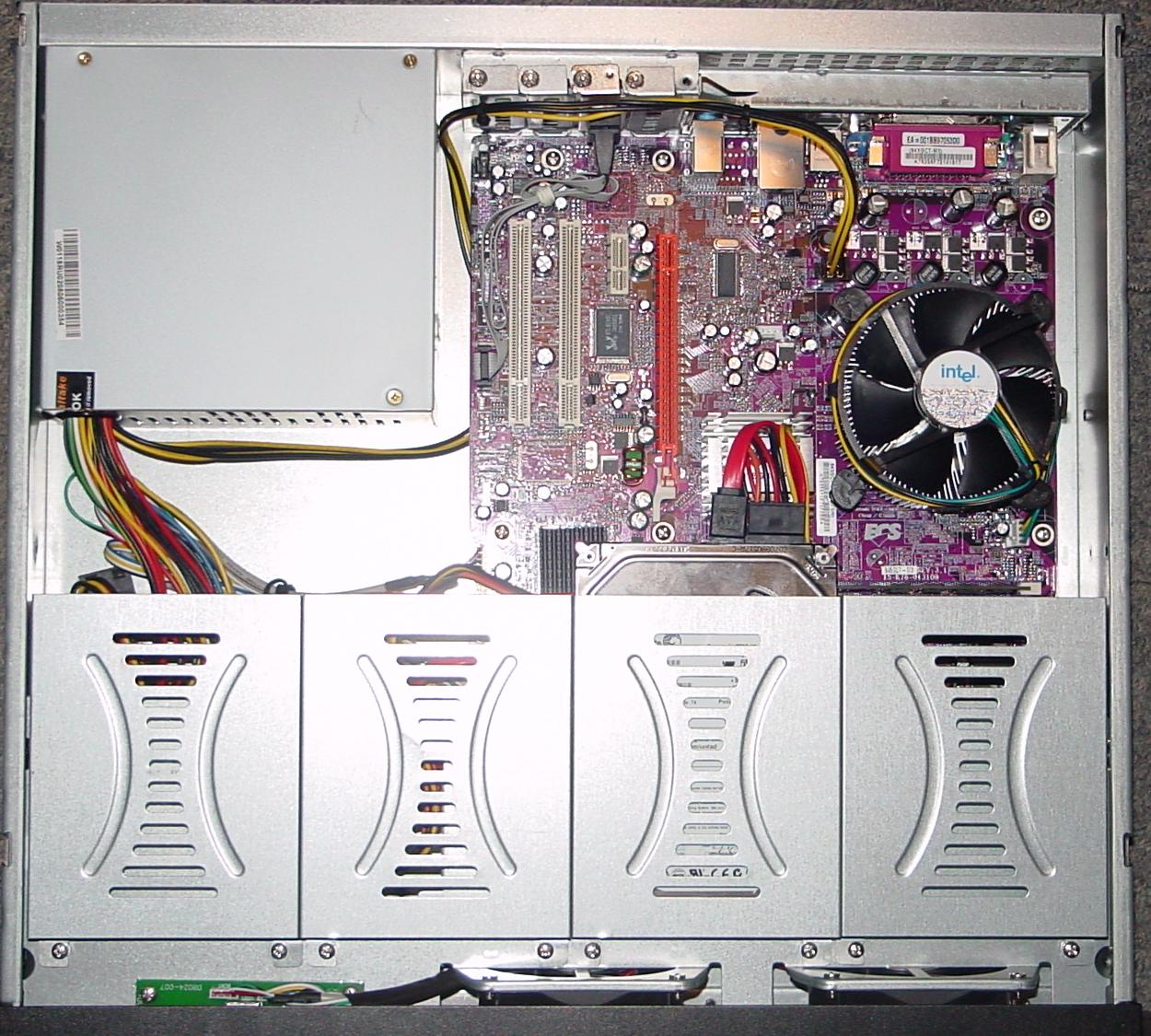
EZ Automation CAP/EAS Encoder-Decoder www.voicetracking.com (810) 895-2040 © 2005-2012 The EZ Automation CAP/EAS Encoder-Decoder is built from commercially available computer hardware. The software can operate on a wide variety of hardware. The hardware for the unit was based on needed features. Other important parts include an SATA drive, DIMM memory, 2 status LED’s, and a simple speaker. The unit is controlled via a keyboard/mouse/VGA monitor display, LAN and/or external serial port. Here is a diagram of the overall schematics of the unit, which is in essence, a rack-mount Windows™ computer. Expansion Options The motherboard has a full set of I/O ports and connectors: • Two PS/2 ports for mouse and keyboard • Two serial ports • One parallel port • One VGA port • Four USB ports • One LAN port • Audio jacks for rear line-in and lineout. Header for extra line-in and lineout. Integrated I/O The motherboard comes with the following expansion options: • One PCI Express x16 slot for Graphic Interface • One PCI Express x1 slot • Two 32-bit PCI v2.3 compliant slots • One 40-pin IDE low profile header that support two IDE devices • One floppy disk drive interface • Four 7-pin SATA connectors The motherboard supports UDMA bus mastering with transfer rates of 100/66/33 Mb/s. EZ Automation 3302 N. Van Dyke Imlay City, MI 48444 (810) 895-2040 www.voicetracking.com
Test Report
EZ Automation CAP/EAS Encoder-Decoder www.voicetracking.com (810) 895-2040 © 2005-2012 The EZ Automation CAP/EAS Encoder-Decoder was tested to comply with part 11 of the FCC rules (the assigned FCC ID is OTQEAS). It uses an Intel x86 platform which operates on Microsoft Windows™. All input and output functions are contained within software. FSK and tone-tone attention signals are generated digitally in software. This includes the following functions: The Left/Right audio input serves as inputs from at least two audio receivers (inputs 3 and 4 are optional). An "HD" audio output serves as the output of FSK, tone-tone and audio output of alert message. Configuration of device is done through standard mouse, keyboard and VGA- type monitor. The decoding/encoding status of EAS messages is shown on VGA monitor. Two serial ports and a network interface are provided for operational control. § 11.32 EAS Encoder. (a) EAS Encoders must at a minimum be capable of encoding the EAS protocol described in §11.31 and providing the EAS code transmission requirements described in §11.51. EAS encoders must additionally provide the following minimum specifications: The Unit complies with 11.31() for EAS protocol. During transmissions, this is generated digitally within software and outputted via a sound card. The unit is also capable to receiving the EAS protocol via audio card inputs, and complies with the revised provisions for expanded codes. (1) Encoder programming. Access to encoder programming shall be protected by a lock or other security measures and be configured so that authorized personnel can readily select and program the EAS Encoder with Originator, Event and Location codes for either manual or automatic operation. The unit contains a password lock to prevent unauthorized access. The unit can be programmed with Originator, Event and Location codes for either manual or automatic operation. (2) Inputs. The encoder shall have at least one input port used for audio messages and at least one input port used for data messages. The unit has two audio inputs (left/right can be used separately to equal four audio inputs), two audio outputs, two standard serial ports, four USB serial ports, one parallel port., and one Ethernet port. (3) Outputs. The encoder shall have at least one audio output port and at least one data output port. The unit has two audio inputs (left/right can be used separately to equal four audio inputs), two audio outputs, two standard serial ports, four USB serial ports, one parallel port., and one Ethernet port. (4) Calibration. EAS Encoders must provide a means to comply with the modulation levels required in §11.51(f). The unit can output separate test tones for level calibration. (5) Day-Hour-Minute and Identification Stamps. The encoder shall affix the JJJHHMM and LLLLLLLL codes automatically to all initial messages. The unit complies with this requirement for Day-Hour-Minute and Identification Stamps. (6) Program Data Retention. Program data and codes shall be retained even with the power removed. The unit complies with this requirement, as everything is stored in multi-gigabyte storage device. (7) Indicator. An aural or visible means that it activated when the Preamble is sent and deactivated at the End of Message code. The unit complies with this requirement and provides a visible means via a VGA-type monitor (8) Spurious Response. All frequency components outside 200 to 4000 Hz shall be attenuated by 40 dB or more with respect to the output levels of the mark or space frequencies. The unit complies with this requirement, as all tones are generated digitally and output via a "HD" audio card. The spurious components were measured on a Leader LDM-170 Distortion Meter and was greater than 40 dB in every instance. This test was performed September 30, 2012. (9) Attention Signal generator. The encoder must provide an attention signal that complies with the following: (i) Tone Frequencies. The audio tones shall have fundamental frequencies of 853 and 960 Hz and not vary over ±0.5 Hz. The unit complies with this requirement, as all tones are generated digitally and outputted via a "HD" audio card. The frequency output was measured with a Radio Shack 22-306 Frequency Counter. The two frequencies measured to 852.9 Hz and 960.0 Hz. This test was performed September 30, 2012. (ii) Harmonic Distortion. The total harmonic distortion of each of the audio tones may not exceed 5% at the encoder output terminals. The unit complies with this requirement, as all tones are generated digitally and outputted via a "HD" audio card. The THD + Noise measured on a Leader LDM-170 were less than 0.7% on any tone This test was performed September 30, 2012. (iii) Minimum Level of Output. The encoder shall have an output level capability of at least +8 dBm into a 600 Ohm load impedance at each audio tone. A means shall be provided to permit individual activation of the two tones for calibration of associated systems. The unit complies with this requirement, as all tones are generated digitally and outputted via a "HD" audio card. To meet the +8 dBm requirement the audio must exceed 5.503 Vpp. A Tektronix 212 oscilloscope was used to verify an output greater than the requirement. This test was performed September 30, 2012. (iv) Time Period for Transmission of Tones . The encoder shall have timing circuitry that automatically generates the two tones simultaneously for a time period of 8 seconds. The unit complies with this requirement, as all two-tones are generated digitally for 8-seconds and outputted via a "HD" audio card. (v) Inadvertent activation. The switch used for initiating the automatic generation of the simultaneous tones shall be protected to prevent accidental operation. The unit contains a password lock to prevent unauthorized access (vi) Indicator Display. The encoder shall be provided with a visual and/or aural indicator which clearly shows that the Attention Signal is activated. The unit c…
Text truncated - open the document above for the full version.
Test Report
EZ Automation CAP/EAS Encoder-Decoder www.voicetracking.com (810) 895-2040 © 2005-2013 The EZ Automation CAP/EAS Encoder-Decoder was tested to comply with part 11 of the FCC rules (the assigned FCC ID is OTQEAS). It uses an Intel x86 platform which operates on Microsoft Windows™. All input and output functions are contained within software. FSK and tone-tone attention signals are generated digitally in software. This includes the following functions: The Left/Right audio input serves as inputs from at least two audio receivers (inputs 3 and 4 are optional). An "HD" audio output serves as the output of FSK, tone-tone and audio output of alert message. Configuration of device is done through standard mouse, keyboard and VGA- type monitor. The decoding/encoding status of EAS messages is shown on VGA monitor. Two serial ports and a network interface are provided for operational control. § 11.31 EAS protocol (a) The EAS uses a four part message for an emergency activation of the EAS. The four parts are: Preamble and EAS Header Codes; audio Attention Signal; message; and, Preamble and EAS End Of Message (EOM) Codes. The Unit complies with 11.31() for EAS protocol. During transmissions, this is generated digitally within software and outputted via a sound card. The unit is also capable to receiving the EAS protocol via audio card inputs, and complies with the revised provisions for expanded codes. To test overall compliance, a series of tests were transmitted and received to and from several commonly commercially available EAS Encoder/Decoder Units (Holly-Anne model HU-961, Sage model 1822, Gorman-Redlich model EAS-1). These tests served as a "double-check" of compliance and real-world compatibility with the EAS Protocol. These tests were conducted during September 2012. (1) The Preamble and EAS Codes must use Audio Frequency Shift Keying at a rate of 520.83 bits per second to transmit the codes. Mark frequency is 2083.3 Hz and space frequency is 1562.5 Hz. Mark and space time must be 1.92 milliseconds. Characters are ASCII seven bit characters as defined in ANSI X3.4-1977 ending with an eighth null bit (either 0 or 1) to constitute a full eight-bit byte. See attached pictures of header FSK tones as captured from audio output, as viewed in Cool Edit audio editor program. (2) The Attention Signal must be made up of the fundamental frequencies of 853 and 960 Hz. The two tones must be transmitted simultaneously. The Attention Signal must be transmitted after the EAS header codes. See attached pictures of two-tone attention signal as captured from the units audio output, as viewed in Cool Edit audio editor program. (3) The message may be audio, video or text. (b) The ASCII dash and plus symbols are required and may not be used for any other purpose. Unused characters must be ASCII space characters. FM or TV call signs must use a slash ASCII character number 47 (/) in lieu of a dash. (c) The EAS protocol, including any codes, must not be amended, extended or abridged without FCC authorization. The EAS protocol and message format are specified in the following representation. Examples are provided in FCC Public Notices. [PREAMBLE]ZCZC-ORG-EEE-PSSCCC+TTTT-JJJHHMM-LLLLLLLL-(one second pause) [PREAMBLE]ZCZC-ORG-EEE-PSSCCC+TTTTpJJJHHMM-LLLLLLLL-(one second pause) [PREAMBLE]ZCZC-ORG-EEE-PSSCCC+TTTT-JJJHHMM-LLLLLLLL-(at least a one second pause) (transmission of 8 to 25 seconds of Attention Signal) (transmission of audio, video or text messages) (at least a one second pause) [PREAMBLE]NNNN (one second pause) [PREAMBLE]NNNN (one second pause) [PREAMBLE]NNNN (at least one second pause) See attached pictures of relayed Required Monthly Test as captured from audio output, as viewed in Cool Edit audio editor program (If a higher resolution jpeg file is required please contact us.) The sample shows the three FSK Header Burst with one second pause between each one, at least one second pause, relayed audio content, at least one second pause, and the three ‘NNNN’ FSK bursts (EOM). [PREAMBLE] This is a consecutive string of bits (sixteen bytes of AB hexadecimal [8 bit byte 10101011]) sent to clear the system, set AGC and set asynchronous decoder clocking cycles. The preamble must be transmitted before each header and End of Message code. ZCZC—This is the identifier, sent as ASCII characters ZCZC to indicate the start of ASCII code. ORG—This is the Originator code and indicates who originally initiated the activation of the EAS. These codes are specified in paragraph (d) of this section. EEE—This is the Event code and indicates the nature of the EAS activation. The codes are specified in paragraph (e) of this section. The Event codes must be compatible with the codes used by the NWS Weather Radio Specific Area Message Encoder (WRSAME). PSSCCC—This is the Location code and indicates the geographic area affected by the EAS alert. There may be 31 Location codes in an EAS alert. The Location code uses the codes described in the American National Standards Institute (ANSI) standard, ANSI INCITS 31-2009 (“Information technology—Codes for the Identification of Counties and Equivalent Areas of the United States, Puerto Rico, and the Insular Areas”). Each state is assigned an SS number as specified in paragraph (f) of this section. Each county and some cities are assigned a CCC number. A CCC number of 000 refers to an entire State or Territory. P defines county subdivisions as follows: 0 = all or an unspecified portion of a county, 1 = Northwest, 2 = North, 3 = Northeast, 4 = West, 5 = Central, 6 = East, 7 = Southwest, 8 = South, 9 = Southeast. Other numbers may be designated later for special applications. The use of county subdivisions will probably be rare and generally for oddly shaped or unusually large counties. Any subdivisions must be defined and agreed to by the local officials prior to use. +TTTT—This indicates the valid time period of a message in 15 minute segments up to one hour and then in 30 minute segments bey…
Text truncated - open the document above for the full version.
Test Report
EZ Automation CAP/EAS Encoder-Decoder www.voicetracking.com (810) 895-2040 © 2005-2013 The EZ Automation CAP/EAS Encoder-Decoder was tested to comply with part 11 of the FCC rules (the assigned FCC ID is OTQEAS). It uses an Intel x86 platform which operates on Microsoft Windows™. All input and output functions are contained within software. FSK and tone-tone attention signals are generated digitally in software. This includes the following functions: The Left/Right audio input serves as inputs from at least two audio receivers (inputs 3 and 4 are optional). An "HD" audio output serves as the output of FSK, tone-tone and audio output of alert message. Configuration of device is done through standard mouse, keyboard and VGA- type monitor. The decoding/encoding status of EAS messages is shown on VGA monitor. Two serial ports and a network interface are provided for operational control. § 11.31 EAS protocol (a) The EAS uses a four part message for an emergency activation of the EAS. The four parts are: Preamble and EAS Header Codes; audio Attention Signal; message; and, Preamble and EAS End Of Message (EOM) Codes. The Unit complies with 11.31() for EAS protocol. During transmissions, this is generated digitally within software and outputted via a sound card. The unit is also capable to receiving the EAS protocol via audio card inputs, and complies with the revised provisions for expanded codes. To test overall compliance, a series of tests were transmitted and received to and from several commonly commercially available EAS Encoder/Decoder Units (Holly-Anne model HU-961, Sage model 1822, Gorman-Redlich model EAS-1). These tests served as a "double-check" of compliance and real-world compatibility with the EAS Protocol. These tests were conducted during September 2012. (1) The Preamble and EAS Codes must use Audio Frequency Shift Keying at a rate of 520.83 bits per second t…
Text truncated - open the document above for the full version.
Contact Information
Applicant
Edward Czelada
Technical Specifications
| # | Rule Parts | Frequency Range | Power Output |
|---|---|---|---|
| 1 | 11 | - | - |