OUULL4Vehicle tracking and telematics unit
Microlise Limited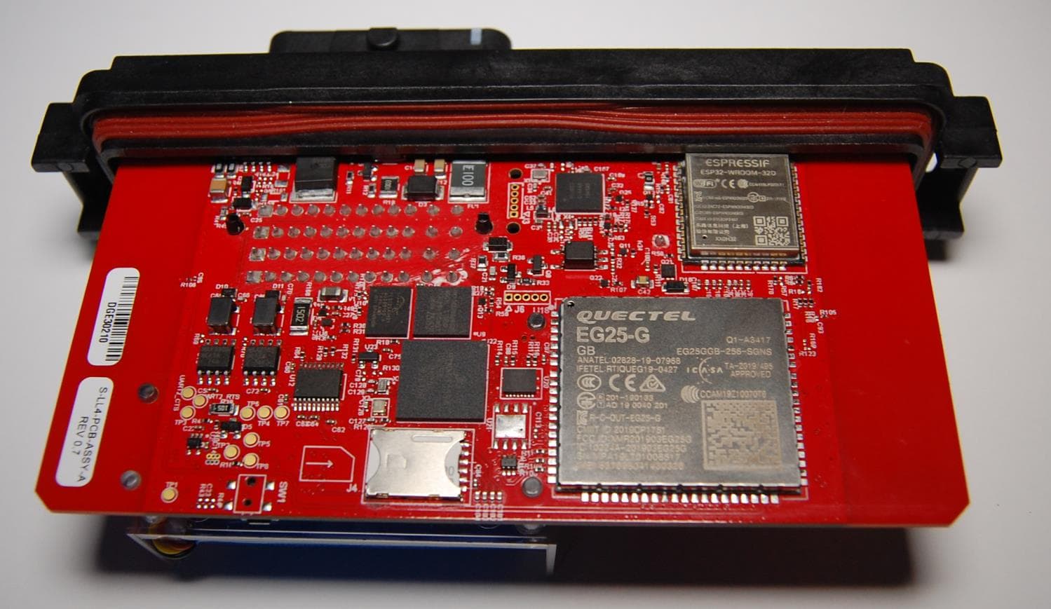
Click to zoom
Application Details
- Equipment Class
- DTS - Digital Transmission System
- Date of Grant
- Feb 04, 2021
- Application Purpose
- Original Equipment
- Date of Application
- Feb 04, 2021
- Equipment Note
- Vehicle tracking and telematics unit
- Frequency Range
- 2402.00000000 - 2480.00000000
- Company
- Microlise Limited
- Country
- United Kingdom
Documents & Files
Document Text
Text extracted from the exhibit documents filed with the FCC. Open a document above to read the original.
Users Manual
CLASSIFICATION: PUBLIC DATE OF PRINT: 20 January 2021 LiveLink 4 - 728/J8518 Technical Manual Issue 1.0 20 January 2021 DOCUMENT SECURITY CLASSIFICATION Public No existing release restrictions other than normal non disclosure rules CLASSIFICATION: PUBLIC DATE OF PRINT: 20 January 2021 Contents Contents ............................................................................................................................................................ 2 Overview ............................................................................................................................................................ 3 Installation .......................................................................................................................................................... 4 Description of operation ..................................................................................................................................... 5 Service / Repair ................................................................................................................................................. 5 Block Diagram ................................................................................................................................................... 6 Technical Specification ...................................................................................................................................... 7 1.1 Cellular RF Power Output .................................................................................................................. 8 Regulatory and Type Approvals ........................................................................................................................ 9 1.1 CE ...................................................................................................................................................... 9 1.2 E-Mark ............................................................................................................................................. 10 1.3 Global Approvals ............................................................................................................................. 10 1.3.1 Canada (ISED)......................................................................................................................... 10 1.3.2 United States (FCC) ................................................................................................................ 10 Issue History .................................................................................................................................................... 10 CLASSIFICATION: PUBLIC DATE OF PRINT: 20 January 2021 Overview The LiveLink 4 is a battery-backed vehicle tracking and telematics unit utilising GPS, GSM / GPRS, BLE and Wi-Fi technology. CLASSIFICATION: PUBLIC DATE OF PRINT: 20 January 2021 Installation LiveLink 4 units are designed to be installed both within the vehicle cab in a protected environment and externally fitted. Depending on the application the device may be permanently powered, or only powered periodically. In either application, the LiveLink 4 is designed to make efficient use of the power available through the use of sleep modes when there is no activity. When selecting a suitable mounting location, please be aware of: • Excessive temperatures • Corrosive fluids • Areas where the unit may obstruct the driver's view or impede the operation of the vehicle • Locations that may shield the unit affecting GPS and/or GPRS reception. • Unit and antenna separation distance of at least 20cm from all persons, animals and other antennae or transmitters. • Local or international regulations regarding the fitment of equipment within vehicles. The installation must be carried out following FCS1362:2010 or later, by a Microlise approved installer. The recommend installation to vehicles is to be mounted on 2 x M5 fixings, tightened to 2Nm. For installation the unit must be fused on the power input at 2A, and on the ignition input at 1A using automotive fuses and fuse holders tested to relevant safety standards appropriate for the intended country of use. The minimum connections to the vehicle for unit operation are listed below. Connection Pin Number Fused Power 4M Yes – 2A Ignition 2M Yes – 1A Ground 3M No Ignition Ground 2L No Refer to relevant product guidelines and vehicle surveys for installation specifics. CLASSIFICATION: PUBLIC DATE OF PRINT: 20 January 2021 Description of operation Providing external power is applied, or the internal battery is sufficiently charged, and the unit is within GPS and GPRS coverage the unit will periodically (based on time and/or distance, and configuration) transmit location and telematics information to the relevant Microlise system. If out of GPRS coverage then messages are stored into non-volatile Flash memory for transmission later when a GPRS connection can be established. Whilst operating on external power the unit will charge the internal battery as required. Two CAN interfaces are incorporated which are typically used to either listen for or request information on automotive CAN busses. The unit incorporates an RS232 interface which can be used for connection of a variety of peripherals, e.g. Mobile Data Terminals, refrigeration temperature monitoring equipment, printers, sensors or other devices. The unit incorporates six digital inputs. One is available for monitoring ignition status, another for engine run, the remainder are general-purpose inputs which can be used for monitoring doors switches, panic buttons or other digital signals. A real-time clock is incorporated for time-stamping all events recorded by the unit. The unit monitors its internal temperature. Battery charging is only permitted when the temperature is within the specified limits of the battery pack. The Bluetooth interface can be used for diagnostics or connection to peripheral devices, e.g. a data termin…
Text truncated - open the document above for the full version.
Cover Letter(s)
Microlise Group Limited - Registered in England and Wales No. 01670983 Microlise Limited - Registered in England and Wales No. 3037936 Microlise Engineering Limited - Registered in England and Wales No. 2211125 Registered Office: Farrington Way, Eastwood, Nottingham, NG16 3AG VAT Number 694 5425 02 Microlise Ltd Farrington Way, Eastwood Nottingham, NG16 3AG United Kingdom Tel: +44 (0) 1773 537000 Fax: +44 (0) 1773 537373 Email: [email protected] Website: www.microlise.com 20 March 2020 LETTER OF AGENCY Element Materials Technology 100 Frobisher Business Park Malvern Worcestershire WR14 1BX UK To Whom It May Concern: We certify that we are not subject to denial of federal benefits, that includes FCC benefits, pursuant to Section 5301 of the Anti-Drug Abuse ACT of 1988, U.S.C. 862. Further, no party, as defined in 47 CFR 1.2002(b), to the application, is subject to denial of federal benefits, that includes FCC benefits. Thank you for your attention to this matter. Yours faithfully Microlise Ian Dickinson Director of Hardware Development
Cover Letter(s)
Microlise Group Limited - Registered in England and Wales No. 01670983 Microlise Limited - Registered in England and Wales No. 3037936 Microlise Engineering Limited - Registered in England and Wales No. 2211125 Registered Office: Farrington Way, Eastwood, Nottingham, NG16 3AG VAT Number 694 5425 02 Microlise Ltd Farrington Way, Eastwood Nottingham, NG16 3AG United Kingdom Tel: +44 (0) 1773 537000 Fax: +44 (0) 1773 537373 Email: [email protected] Website: www.microlise.com 15 December 2020 Attn: Industry Canada & FCC Authority to Act as Agent I appoint Element Materials Technology to act as our agent in the preparation of this application for equipment certification. I certify that submitted documents properly describe the device or system for which equipment certification is sought. I also certify that each unit manufactured, imported or marketed, as defined in the FCC and Industry Canada regulations will have affixed to it a label identical to that submitted for approval with this application. For instances where our authorized agent signs the application for certification on our behalf, I acknowledge that all responsibility for complying with the terms and conditions for Certification, as specified by Element Materials Technology (Element), still resides with Microlise Limited, Farrington Way, Eastwood, NG16 3AG, United Kingdom Dated this 15th day of December 2020. Agency Agreement Expiration Date: 15 th December 2021 By: __________________________ Ian Dickinson (Signature) (Print Name) Title: Director of Hardware Development On behalf of: Microlise Limited (Company Name) Telephone: +44(0)1773 537000
Cover Letter(s)
Microlise Group Limited - Registered in England and Wales No. 01670983 Microlise Limited - Registered in England and Wales No. 3037936 Microlise Engineering Limited - Registered in England and Wales No. 2211125 Registered Office: Farrington Way, Eastwood, Nottingham, NG16 3AG VAT Number 694 5425 02 Microlise Ltd Farrington Way, Eastwood Nottingham, NG16 3AG United Kingdom Tel: +44 (0) 1773 537000 Fax: +44 (0) 1773 537373 Email: [email protected] Website: www.microlise.com 07 December 2020 Federal Communications Commission Authorization and Evaluation Division 7435 Oakland Mills Road Columbia, Maryland 21046 Re: Request for confidentiality FCC ID: OUULL4 To whom it may concern, We hereby respectfully request that under the provision of 47 CFR 0.459 and 0.457(d) the documents listed below and attached with this application for certification be provided with confidential status. • Track and component layouts • Operational and Technical Documents • Block Diagrams & Schematics • Parts and BoM Lists Any exhibit / information for which we have requested confidentiality, but which may not be accorded such treatment by the FCC, should be returned to us. The documents listed above contain trade secrets that are treated as confidential by us. Substantial competitive harm to us could result should they be made available to the public. Sincerely, Ian Dickinson Director of Hardware Development
External Photos
LL4 Product Photographs - Issue 1.1 Page 1 of 15 LL4 - Modules Cellular / GNSS Module Cellular Antenna LL4 Product Photographs - Issue 1.1 Page 2 of 15 GNSS Antenna Wi-Fi Bluetooth Module LL4 Product Photographs - Issue 1.1 Page 3 of 15 Wi-Fi/Bluetooth and BLE Circuitry LL4 Product Photographs - Issue 1.1 Page 4 of 15 LL4 – Internal Photographs PCB – Top Side PCB – Under Side LL4 Product Photographs - Issue 1.1 Page 5 of 15 Assembled Unit – Top Side LL4 Product Photographs - Issue 1.1 Page 6 of 15 Assembled Unit – Top Side (Battery Removed) LL4 Product Photographs - Issue 1.1 Page 7 of 15 Under Side LL4 Product Photographs - Issue 1.1 Page 8 of 15 Assembled Unit – Left Side LL4 Product Photographs - Issue 1.1 Page 9 of 15 Assembled Unit – Right Side LL4 Product Photographs - Issue 1.1 Page 10 of 15 Assembled Unit – Rear LL4 Product Photographs - Issue 1.1 Page 11 of 15 LL4 – External Photographs Top Side LL4 Product Photographs - Issue 1.1 Page 12 of 15 Under Side LL4 Product Photographs - Issue 1.1 Page 13 of 15 Left Side LL4 Product Photographs - Issue 1.1 Page 14 of 15 Right Side LL4 Product Photographs - Issue 1.1 Page 15 of 15 Front Rear Document Versions Issue Date Name Changes 1.0 28/07/20 James Marley Initial version. 1.1 09/10/20 James Marley Updated following initial RED review
ID Label/Location Info
LL4 FCC / IC Labelling - Issue 1.0 Page 1 of 2 LL4 – FCC / IC Labelling IMEI Label LL4 FCC / IC Labelling - Issue 1.0 Page 2 of 2 Position on Unit Document Versions Issue Date Name Changes 1.0 17/12/20 James Marley Initial version. 1.1 11/01/21 James Marley Updated to correct IC number
Internal Photos
LL4 Product Photographs - Issue 1.1 Page 1 of 15 LL4 - Modules Cellular / GNSS Module Cellular Antenna LL4 Product Photographs - Issue 1.1 Page 2 of 15 GNSS Antenna Wi-Fi Bluetooth Module LL4 Product Photographs - Issue 1.1 Page 3 of 15 Wi-Fi/Bluetooth and BLE Circuitry LL4 Product Photographs - Issue 1.1 Page 4 of 15 LL4 – Internal Photographs PCB – Top Side PCB – Under Side LL4 Product Photographs - Issue 1.1 Page 5 of 15 Assembled Unit – Top Side LL4 Product Photographs - Issue 1.1 Page 6 of 15 Assembled Unit – Top Side (Battery Removed) LL4 Product Photographs - Issue 1.1 Page 7 of 15 Under Side LL4 Product Photographs - Issue 1.1 Page 8 of 15 Assembled Unit – Left Side LL4 Product Photographs - Issue 1.1 Page 9 of 15 Assembled Unit – Right Side LL4 Product Photographs - Issue 1.1 Page 10 of 15 Assembled Unit – Rear LL4 Product Photographs - Issue 1.1 Page 11 of 15 LL4 – External Photographs Top Side LL4 Product Photographs - Issue 1.1 Page 12 of 15 Under Side LL4 Product Photographs - Issue 1.1 Page 13 of 15 Left Side LL4 Product Photographs - Issue 1.1 Page 14 of 15 Right Side LL4 Product Photographs - Issue 1.1 Page 15 of 15 Front Rear Document Versions Issue Date Name Changes 1.0 28/07/20 James Marley Initial version. 1.1 09/10/20 James Marley Updated following initial RED review
Test Report
RF915 7.0 Report on the Radio Testing For Microlise Engineering Limited on JCB Livelink 4 Report no. TRA-048544-47-05A 29 January 2021 RF915 7.0 REPORT ON THE RADIO TESTING OF A Microlise Engineering Limited JCB Livelink 4 WITH RESPECT TO SPECIFICATION FCC 47CFR 15.247 TEST DATE: 2020-10-15 to 2020-10-23 Written by: D Moncayola Radio Test Engineer Approved by: J Charters Lab Manager Date: 29 January 2021 Disclaimers: [1] THIS DOCUMENT MAY BE REPRODUCED ONLY IN ITS ENTIRETY AND WITHOUT CHANGE [2] THE RESULTS CONTAINED IN THIS DOCUMENT RELATE ONLY TO THE ITEM(S) TESTED Report Number: TRA-048544-47-05A Issue: A Report Number: TRA-048544-47-05A RF915 7.0 Page 3 of 38 1 Revision Record Issue Number Issue Date Revision History A 29 January 2021 Original Report Number: TRA-048544-47-05A RF915 7.0 Page 4 of 38 2 Summary TEST REPORT NUMBER: TRA-048544-47-05A WORKS ORDER NUMBER: TRA-048544-05 PURPOSE OF TEST: USA: Testing of radio frequency equipment per the relevant authorization procedure of chapter 47 of CFR (code of federal regulations) Part 2, subpart J. TEST SPECIFICATION(S): 47CFR15.247 EQUIPMENT UNDER TEST (EUT): JCB Livelink 4 FCC IDENTIFIER: TBC EUT SERIAL NUMBER: DGG64967 MANUFACTURER/AGENT: Microlise Engineering Limited ADDRESS: Farrington Way Eastwood Nottingham Nottinghamshire NG16 3AG United Kingdom CLIENT CONTACT: Craig White 01773 537000 [email protected] ORDER NUMBER: PO804323 TEST DATE: 2020-10-15 to 2020-10-23 TESTED BY: D Moncayola S Garwell Element Report Number: TRA-048544-47-05A RF915 7.0 Page 5 of 38 2.1 Test Summary Test Method and Description 47CFR15 Applicable to this equipment Result / Note Radiated spurious emissions (restricted bands of operation and cabinet radiation) 15.205 Pass AC power line conducted emissions 15.207 Note 1 Occupied bandwidth 15.247(a)(2) Pass Conducted carrier power Peak 15.247(b)(3) Pass Max. Conducted / radiated RF power out-of-band 15.247(d) Pass Power spectral density, conducted 15.247(e) Pass Calculation of duty correction 15.35(c) Note 2 Notes: 1- Battery powered device, it is not going to be connected to the mains. 2- Duty ≥ 98 % The results contained in this report relate only to the items tested, in the condition at time of test, and were obtained in the period between the date of initial receipt of samples and the date of issue of the report. The apparatus was set up and exercised using the configurations, modes of operation and arrangements defined in this report only. Any modifications made are identified in Section 8 of this report. Particular operating modes, apparatus monitoring methods and performance criteria required by the standards tested to have been performed except where identified in Section 5.2 of this test report (Deviations from Test Standards). Report Number: TRA-048544-47-05A RF915 7.0 Page 6 of 38 3 Contents 1 Revision Record ................................................................................................................................ 3 2 Summary ........................................................................................................................................... 4 2.1 Test Summary ........................................................................................................................... 5 3 Contents ............................................................................................................................................ 6 4 Introduction ....................................................................................................................................... 7 5 Test Specifications ............................................................................................................................ 8 5.1 Normative References .............................................................................................................. 8 5.2 Deviations from Test Standards ................................................................................................ 8 6 Glossary of Terms ............................................................................................................................. 9 7 Equipment Under Test .................................................................................................................... 10 7.1 EUT Identification .................................................................................................................... 10 7.2 System Equipment .................................................................................................................. 10 7.3 EUT Mode of Operation .......................................................................................................... 10 7.3.1 Transmission ................................................................................................................... 10 7.4 EUT Radio Parameters ........................................................................................................... 10 7.4.1 General ........................................................................................................................... 10 7.5 EUT Description ...................................................................................................................... 10 8 Modifications ................................................................................................................................... 11 9 EUT Test Setup............................................................................................................................... 11 9.1 Block Diagram ......................................................................................................................... 11 9.2 General Set-up Photograph .................................................................................................... 11 9.3 Measurement software ............................................................................................................ 12 10 Gene…
Text truncated - open the document above for the full version.
Test Setup Photos
Report Number: TRA-048544-47-05A RF915 7.0 Page 11 of 38 8 Modifications No modifications were performed during this assessment. 9 EUT Test Setup 9.1 Block Diagram The following diagram shows basic EUT interconnections with cable type and cable lengths identified: 9.2 General Set-up Photograph The following photograph shows basic EUT set-up: EUT Power Supply 27 Vdc Report Number: TRA-048544-47-05A RF915 7.0 Page 15 of 38 11.5 Test Set-up Photograph 11.6 Test Equipment Equipment Equipment Element Due For Description Manufacturer Type No Calibration Spectrum Analyser R&S FSU26 REF909 2021-07-09 Bilog Chase CBL611/A U573 2021-09-19 Log Periodic Ant Chase UPA6108 L203 2022-06-16 Pre Amp Watkins Johnson 6201-69 U372 2021-02-26 Pre Amp Agilent 8449 L572 2021-10-19 1-18GHz Horn EMCO 3115 L139 2021-07-16 Horn 18-26GHz (&U330) Flann 20240-20 L300 2022-04-23 Radio Chamber - PP Rainford EMC ATS REF940 2021-12-09
Contact Information
Applicant
Ian Dickinson(Director of Technical Services)
Test Firm
Element Materials Technology Warwick LtdNeil Roche
Technical Specifications
| # | Rule Parts | Frequency Range | Power Output |
|---|---|---|---|
| 1 | 15C | 2.40 GHz - 2.48 GHz | 30.00 µW |
Other Applications from Microlise Limited
OUUMTU4
Oct 24, 2012Vehicle tracking and telematics unit
Equipment Class
JBP - Part 15 Class B Computing Device Peripheral