OUZTL603LDCordless Telephone System(Transmitter Portion of B
TCL Communication Int'l Ltd.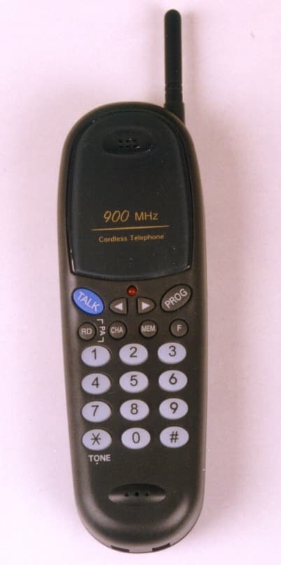
Click to zoom
Application Details
- Equipment Class
- ETS - Part 15 Cordless Telephone System
- Date of Grant
- Mar 23, 2000
- Application Purpose
- Original Equipment
- Date of Application
- Jan 17, 2000
- Equipment Note
- Cordless Telephone System(Transmitter Portion of B
- Frequency Range
- 925.30000000 - 927.25000000
- Company
- TCL Communication Int'l Ltd.
- Country
- Hong Kong
Documents & Files
Document Text
Text extracted from the exhibit documents filed with the FCC. Open a document above to read the original.
Users Manual
USER GUIDE MODEL : TL603-LD 900MHz 40 Channel Cordless Telephone Before operating the unit, please read this manual thoroughly and retain it for future reference. 1 TABLE OF CONTENTS BEFORE OPERATING THE PHONE 1. Features 2. Checking the package contents IDENTIFYING THE PARTS 3. Base unit 4. Cordless handset INSTALLATION 5. Connecting the base phone 6. Installing the battery into the handset 7. Charging the battery pack OPERATING THE PHONE 8. Change the system security code 9. Adjusting the ringer 10. Adjusting the receiver volume 11. Making a call 12. Answer a call 13. Redial the last number 14. Channel selection 15. FLASH function 16. Store number in memory 17. Making memory dialing calls 18. Page the handset 19. Battery low in handset 20. Replacing the Battery 21. Choosing Tone or Pulse Dialing 22. Setting the standby time of Handset battery TROUBLE SHOOTING 23. Error tone 24. Interference 25. Malfunction IMPOTANT NOTES 26. The factory presetting 27. Specification 2 COMPLIES WITH PART 68 FCC RULES HAC MODEL NO.: TL603-LD FCC REGISTRATION NO.: FCC ID : R INGEER EQUIVANENCE : TCL Communication Int’l Ltd USOC JACK : RJ11C, RJ11W MADE IN CHINA DATE : CAUTION : ANY CHANGES OR MODIFICATION IN CONSTRUCTION OF THIS DEVICE WHICH ARE NOT EXPRESSLY APPROVED BY THE PARTY RESPONSIBLE FOR COMPLIANCE COULD VOID THE USER’S AUTHORITY TO OPERATE THE EQUIPMENT. PRIVACY OF COMMUNICATIONS MAY NOT BE ENSURED WHEN USING THIS PHONE. THIS DEVICE COMPLIES WITH PART 15 OF THE FCC RULES. OPERATION IS SUBJECT TO THE FOLLOWING TWO CONDITIONS : (1) THIS DEVICE MAY NOT CAUSE HARMFUL INTERFENCE, AND (2) THIS DEVICE MUST ACCEPT ANY INTERFERRENCE RECEIVED, INCLUDING INTERFERENCE THAT MAY CAUSE UNDESIRED OPERATION. BEFORE OPERATING THE PHONE 1. Features 1) U.S.A. 40-channel auto select. 2) Random 20-bit digital security code. 3) Manual change channel with channel availability test. 4) Out-of-range indication and release of an engaged line. 5) Volume High / Low selection on handset. 6) Ten 16-digit speed dial memory 7) Last number redial (up to 32 digits). 8) Flash (100 / 300 / 600 mS selectable). 9) One way paging. (base page handset). 10) Auto receive when handset is lifted off the cradle during ringing. 11) Auto standby for power saving when the handset is at idle mode. 12) Lighted dial keypad(optional) 13) Tone / Pulse dialing 14) 40:60 / 33:66 make / break ratio selectable. 3 15) Pause function. 16) Key tone, error tone and confirmation tone. 17) Low battery indication with warning tone on handset. 18) 4 ringer cadence selectable by handset program key. 2. Checking the package contents Make sure the following items are included in the package. If anything is missing, contact your local dealer. IDENTIFYING THE PARTS 3. Base unit RECHARGEABLE BATTERY DC 9V 200 mA POW ER A DA PTOR HANDSET TEL. LINE BA SE _ + 4 1) ANTENA 2) IN USE / CHARGE INDICATOR Lighting when the unit is in use AND the Handset is placed in the cradle. 3) POWER INDICATOR Lighting when the power input is connected. 4) PAGE BUTTON Press this button to send a page signal to the handset. 5) CHARGING CONTRACT POINT 6) POWER INPUT (DC 9V/300mA) JACK 7) TELEPHONE LINE – IN JACK IDENTIFYING THE PARTS 4. Cordless Handset PA GE POW ER IN USE / CHARGE 900 MHz Cordless Telephone 3 5 6 4 7 1 2 7 5 1) IN USE INDICATOR 2) VOLUME LOW BUTTON 3) TALK BUTTON Let you make or receive a call 4) REDIAL / PAUSE BUTTON Redial the last number called. Pause function when between the dialing digit. 5) CHANNEL BUTTON Allow you to change channel when interference occurs. 6) MICROPHONE 7) ANTENNA 8) RECEIVER 9) VOLUME HIGH BUTTON 6 10) PROGRAM BUTTON Allow you to set the phone setting (Ringer type, Tone / Pulse, M/B, Flash). 11) FLASH BUTTON 12) MEMORY BUTTON Allow you to store telephone number, or recall telephone number up to 16 digits. 13) LING BUTTONS (0-9, */T, #) INSTALLATION 5. Connecting The Base Phone 5.1 Connect the AC power adapter into an AC wall outlet, and the cord plug end into the DC 9V jack in the back the base phone. 5.2 Plug one end of the telephone line cord (supplied) into the TELEPHONE LINE-IN jack and the other end into a telephone outlet. 5.3 Turn the antenna to vertical direction. WARNING 1. Never install telephone jacks during a lighting storm. 2. Never install telephone jacks in wet location unless the telephone line has been disconnected at the network interface. 7 3. Never touch un-insulated telephone wires or terminals unless the telephone line has been disconnected at the network interface. 4. Use caution when installing or modifying telephone lines. 6. Installing the battery into the Handset 6.1 Remove the battery compartment lid. 6.2 Plug the battery pack cord into the connector inside the battery compartment. 6.3 Place the battery pack in the battery compartment. 6.4 Replace the lid by sliding up over the pack until firmly in place. 7. Charging the Battery pack 7.1 Place the handset in the charging cradle, until the CHARGE indicator lights. 7.2 Charge the handset for a full10-12 hours. 7.3 Remove the handset from the charging cradle. 7.4 Press the TALK button and make sure the IN USE indicator does not flash light (The BATTERY LOW indicator flash lights when the handset needs recharging). From then on, recharge the battery pack by placing the handset in the charging cradle when the IN USE indicator flash lights. OPERATING THE PHONE 8. Change the system security code The security code prevents your telephone from being operated by another cordless telephone. The code is changed every time the handset is placed in the charging cradle. 8.1 Place the handset in the charging cradle until the CHARGE indication lights. 8.2 The handset will automatically select a random code from a total of one 1,048,576 combinations. 8 8.3 If the code and channel are changed successfully, there will be a confirmation beep tone from the handset. 8.4 Repeat the procedure until there is a confirmation beep tone from the handset. 9. Adjusting The Ringer Melody There are 4 ki…
Text truncated - open the document above for the full version.
External Photos
EXTERNAL FRONT SIDE EXTERNAL REAR SIDE FCC ID : OUZTL603LD EXTERNAL BOTTOM SIDE FCC ID : OUZTL603LD FCC ID : OUZTL603LD
External Photos
EXTERNAL FRONT SIDE EXTERNAL BOTTOM SIDE FCC ID : OUZTL603LD
ID Label/Location Info
PROPOSED FCC ID. LABEL AND MARKING BOTTOM SIDE
ID Label/Location Info
PROPOSED FCC ID. LABEL AND MARKING BOTTOM SIDE
Internal Photos
INTERNAL TOP SIDE INTERNAL BOTTOM SIDE FCC ID : OUZTL603LD FCC ID : OUZTL603LD
Internal Photos
INTERNAL TOP SIDE INTERNAL BOTTOM SIDE FCC ID : OUZTL603LD FCC ID : OUZTL603LD
Operational Description
TECHNICAL DESCRIPTION A. HAND SET 1. CIRCUIT OF RECEIVING AUDIO Voice signal from Pin No. 11 of RF module (RF1) through Noise Filter Which is consist of R.C and enter into the Compander IC ( IC3) Pin No.15 and out to Pin No.19 of IC3 through Expander and expanding in Q4 and out as voice from receiver. 2. CIRCUIT OF SENDING AUDIO Voice signal from C-MIC enter into the Pin No.8 of Compander IC (IC3) and out from Pin No. 1 of IC3. It enter into Pin No.1 of RF module and send through Antenna after modulating. 3. CIRCUIT OF SENDING POWER SUPPLY & BATT DETECTOR Voltage is 3.6V Ni-Cd Battery on hand set. Battery power is switched to reduce consumption current through Q11. Also if Battery voltage is under 3.3V, Detector IC (IC4) sense it and warning tone come from. 4. CIRCUIT OF CHARGER POWER When put hand set into the charger, battery is charged and shows light LED of charger for confirmation of charging. B. BASE 1. CIRCUIT OF RECEIVING AUDIO Voice signal from Pin No. 11 of RF module (RF1) through Noise Filter Which is consist of R.C and enter into the Compander IC (IC3) Pin No.15 and out to Pin No. 19 of IC3 through Expander and out to Telephone line through HYBRID TRANSFORMER (T1). 2. CIRCUIT OF SENDING AUDIO Voice signal from telephone line enter into the Pin No.8 of Compander IC (IC3) through HYBRID TRANSFORMER (T1). It from Pin No. 1 of IC3 enter into the Pin No.1 of RF module and is sent through Antenna after modulation. 3. CIRCUIT OF AUTO SHUT DOWN SQUELCH input Pin No.14 of CPU (IC1) detect signal from hand set always. If hand set is out of talking distance(range) from base set and (Pin No.14 is high mode) it is over 20 sec, CPU make line to ON HOOK. 4. CIRCUIT OF POWER Power is 110V adapter on Base set and it change AC voltage to DC9V. DC9V remove pulse type noise and AC HUM by L6,7 & C28, 29 and then supply regular voltage to circuit of power through 5V Regulator Voltage IC (IC4). 5. CIRCUIT OF DTMF/RINGER DETECT. DTMF signal from CPU (IC1) is connected with Telephone line through HYBRID TRANSFORMER (T1). Pin No.9 of CPU send ringer data to handset when ring signal which is input to Telephone line enter into the Pin No. 13 of CPU through Photo Coupler (IC5).
Test Report
KTL Korea Testing Laboratory Page 1 of 16 TEST REPORT This test report only responds to the tested sample and shall not be reproduced except in full without written approval of the the Korea Testing Laboratory. Tested and reported by Reviewed by Soun-Kweon Seol , Senior Engineer Seok-Jin Kim , EMC Team Leader KOREA TESTING LABORATORY FG101-01-02-00 222-13, Guro-Dong Guro-Gu Seoul Korea 152-053 http://www.ktl.re.kr Ref. Report No. 99-341-060-1 Name and address of the applicant TCL Commumication Int’l Ltd. Unit 501, 5/F, TCL Tower, 8 Tai Chung Road, Tsuen Wan, N.T., Hong Kong Standard / Test regulation FCC Part 15, Subpart C Test result Pass Incoming date : December 6, 1999 Test item(s) ; Cordless Headset Telephone System (Transmitter Portion of Base System) Model/type ref. ; TL603-LD Manufacturer ; TCL Commumication Equipment Share Co., Ltd. Additional information ; -Required Authorization :Certification -FCC ID. : OUZTL603LD - N o t e : Test report(verification) on receiver portion of this unit is issued on Ref.Report No. 99-341-060-2. Test date : December 24 ∼ ∼∼ ∼ 28, 1999 Issue date : January 17, 2000 Ref. Report No. 99 - 341 – 060-1 Page 2 of 16 TABLE OF CONTENTS I. GENERAL INFORMATION .........................................................................................................3 1. Grantee Name and Mailing Address 2. Manufacturer's Name and Mailing Address 3. Equipment Descriptions 4. Rules and Regulations 5. Measuring Procedure 6. Place of Measurement 7. Date of Measurement . GENERAL REQUIREMENTS OF THE EUT ..............................................................4 1. Labelling Requirement (Section 15.19 and Section 15.214) 2. Information to User (Sections 15.21) 3. Special Accessories (Section 15.27) 4. Digital Security Code (Section 15.214) . CONDUCTED EMISSION MEASUREMENT (Section 15.207)............................................................ 5 - 8 1. Test Procedure 2. Photograph for the worst case configuration 3. Sample Calculation 4. Measurement Data . RADIATED EMISSION MEASUREMENT (Section 15.249) .......................................................9 -14 1. Test Procedure 2. Photograph for the worst case configuration 3. Sample Calculation 4. Measurement Data . OCCUPIED BANDWITH MEASUREMENT (Section 15.249).....................................................15 . TEST EQUIPMENTS USED FOR . FCC COMPLIANCE TESTING ....................................16 Ref. Report No. 99 - 341 – 060-1 Page 3 of 16 . GENERAL INFORMATION 1. Grantee Name and : TCL Commumication Int’l Ltd. Mailing Address Unit 501, 5/F, TCL Tower, 8 Tai Chung Road, Tsuen Wan, N.T., Hong Kong 2. Manufacturer's Name and: TCL Commumication Equipment Share Co., Ltd Mailing AddressTCL Industrial Building, Da Ling Road, Shang Pai, Long Fong, Huizhou, Guangdong, China 516001 3. Equipment Descriptions 3.1 Operating Frequency : 902.800 MHz ~ 904.750 MHz (40 Channel 50KHz Spacing) 3.2 Type of Emission : Frequency Modulation 3.3 Power Supply : DC 9V (AC Adapter) 3.4 Additional Information; - PLL Synthesizer : RU0902B18HKB(SAMSUNG) 4. Rules and Regulations: FCC Part 15, Subpart C 5. Measuring Procedure: ANSI C63.4-1992 6. Place of Measurement : Absorber-lined room(3-Meter) of KTL 7. Date of Measurement 7.1 Conducted Emission: December 28, 1999 7.2 Radiated Emission : December 24~28, 1999 Ref. Report No. 99 - 341 – 060-1 Page 4 of 16 . GENERAL REQUIREMENTS OF THE EUT 1. Labelling Requirement (Section 15.19 and Section 15.214) This device complies with Part 15 of the FCC Rules. Operation is subject to following two condition : this device may not cause harmful interference, and (2) this device must accept any interference received, including interference that may cause undesired operation. 1.1 Location on Enclosure : Bottom side 1.2 How Applied : By Ink-printing on Adhesive Label 2. Information to User (Section 15.21) The following or similar statements were provided in the manual for user instruction. Please refer page 2 of the attached manual for details. CAUTION : Any changes or modifications in construction of this device which are not expressly approved by the party responsible for compliance could void the user's authority to operate the equipment. 3. Special Accessories (Section 15.27) 3.1 Were the special Accessories provided? [ ] yes, [ x ] no 3.2 If yes, details for the special accessories are as follows : 3.3 If yes, were the appropriate instructions provided on the first page of the text concerned with the device? [ ] yes, [ ] no 3.4 Are these accessories provided of the type which can be readily obtained from multiple retail outlets ? [ ] yes, [ ] no And therefore does the manual specify what additional components or accessories are required to used in order to comply with the Rules? [ ] yes, [ ] no 4. Digital Security Code (Section 15.214) 4.1 Was a circuitry for digital security code provided in the cordless telephone system ? [ x ] yes, [ ] no 4.2 If yes, refer to the attached statement on the means and procedures used to achieve the required protection. Privacy of communication may not be ensured when using this phone. Ref. Report No. 99 - 341 – 060-1 Page 5 of 16 . CONDUCTED EMISSION MEASUREMENT (Section 15.207) 1. Test Procedure The base station(EUT) is designed to transmit on one of 40 channels in the band 902.800 to 904.750MHz. Therefore measurements were performed with the equipment operating on three frequencies, which were the top(CH40), middle(CH20), and bottom(CH1) in the band, as per Section 15.31(m). Conducted emission measurements on the EUT were performed by "AC Power Line Conducted Emissions Testing" procedure as per ANSI C63.4. The EUT was set up on a wooden table 0.8 meters height, 1.0 by 1.5 meters in size, placed in the shielded enclosed with a side of wall of which constituted a vertical conducting surface of 2.2m X 3.1m in size to maintain 40Cm from the rear of EUT 2 LISN's(Line Impedance Stabilization Network, EMCO, 3825/2, 50ohm/50uH) were installed and elec…
Text truncated - open the document above for the full version.
Test Report
Ref. Report No. 99 - 341 – 060-1 Page 8 of 16 6 Ref. Report No. 99 - 341 – 060-1 Page 9 of 16 . RADIATED EMISSION MEASUREMENT (Section 15.249) 1. Test Procedure 1.1 Preliminary Testing for Reference The base station(EUT) is designed to transmit on one of 40 channels in the band 902.800 to 904.750MHz. Therefore measurements were performed with the equipment operating on three frequencies, which were the top(CH40), middle(CH20), and bottom(CH1) in the band, as per Section 15.31(m). Preliminary testing was performed in a KTL absorber-lined room to determine the emission characteristics of the EUT. The EUT was placed on the wooden table which has dimensions of 0.8 meters in height, 1 meter in length and 1.5 meters in width. Receiving antenna(Biconical antenna : 30 to 300MHz, Log-periodic antenna : 200 to 1000MHz or Horn Antenna : 1 to 18GHz) was placed at the distance of 1 meter from the EUT. An attempt was made to maximize the emission level with the various configurations of the EUT. The position of connecting cables and antenna of the EUT was changed to find the worst case configuration that produces maximum emission level from the EUT while rotating the table and varying antenna height. Emissions level from the EUT with various configurations were examined on a Spectrum Analyzer connected with a RF amplifier and graphed by a plotter. 1.2 Final Radiated Emission Test at a Absorber-Lined Room The final measurement of radiated field strength was carried out in a KTL Absorber-Lined Room that was listed up at FCC according to the "Radiated Emissions Testing" procedure specified by ANSI C63.4. Based on the test results in preliminary test, measurement was made in same test set up and configuration which produced maximum emission level. Receiving antenna was installed at 3-meter distance from the EUT, and was connected to an EMI receiver or spectrum analyzer(for above 1GHz) with a RF amplifier. Turntable was rotated through 360 degrees and receiving antenna height was varied from 1 to 4 meters above the ground plane to read maximum emission level. If necessary, the radiated emission measurements could be performed at a closer distance than specified distance to ensure higher accuracy and their results were extrapolated to the specified distance using an inverse linear distance extrapolation factor(20dB/decade) as per Section 15.31(f). The maximum emission level from the EUT occurred in such configuration as shown in the following photograph. Ref. Report No. 99 - 341 – 060-1 Page 10 of 16 2. Photograph for the worst case configuration 3. Sample Calculation The emission level measured in decibels above one microvolt (dB ) was converted into microvolt per meter ( /m) as shown in following sample calculation. For example : Measured Value at 902.800MHz 84.7 dB + Antenna Factor29.0 dB + Cable Loss 5.7 dB - Preamplifier30.0 dB - Distance Correction Factor * 0.0 dB ---------------------------------------------------------------------------------------- = Radiated Emission 89.4 dB /m ( =29512.1 /m) * Extrapolated from the measured distance(1.0m) to the specified distance(3m) by an inverse linear distance extrapolation. Ref. Report No. 99 - 341 – 060-1 Page 11 of 16 4. Measurement Data 4.1 Operating Frequency (Bottom : 902.800MHz , CH1) - Resolution Bandwidth : x CISPR Quasi-Peak (6dB Bandwidth : 120kHz for 1GHz below) x Peak (3dB Bandwidth : 1MHz for 1GHz above) - Measurement Distance: 3 Meter Emission Level Frequency (MHz) * D.M. * A.P. Measured Value (dB ) * A.F. + C.L (dB) * A.G. (dB) * D.C.F. (dB) (dB /m)( /m) Limit ( /m) ** Margin (dB) 451.40QH43.425.8-30.0- 39.291.2200 -6.8 902.80QV84.734.7-30.0- 89.4 29512.150000 -4.6 *** 1354.20 PV48.632.2-35.0-9.5 36.365.3500-17.7 *** 1805.60 PV53.535.3-35.0-9.544.3164.1500-9.7 *** 2257.00 PH/V **** <40.0 39.3-35.0-9.5<34.8<55.0500<-19.2 *** 2708.40 PH/V **** <40.0 40.7-35.0-9.5<36.2<64.6500<-17.8 Note * D.M. : Detect Mode (P : Peak, Q : Quasi-Peak, A : Average) A.P. : Antenna Polarization (H : Horizontal, V : Vertical) A.F. : Antenna Factor C.L. : Cable Loss A.G. : Amplifier Gain D.C.F.: Distance Correction Factor ** Margin (dB) = Emission Level (dB) - Limit (dB) *** In the case of these frequencies, the EUT was measured at 1.0m distance for sufficent sensitivity of measurement system. **** < means less than. The observed spectrum analyzer nois floor level with RF preamplifier was 40.0 dBuV Ref. Report No. 99 - 341 – 060-1 Page 12 of 16 4.2 Operating Frequency (Middle : 903.750MHz , CH20) - Resolution Bandwidth : x CISPR Quasi-Peak (6dB Bandwidth : 120kHz for 1GHz below) x Peak (3dB Bandwidth : 1MHz for 1GHz above) - Measurement Distance: 3 Meter Emission Level Frequency (MHz) * D.M. * A.P. Measured Value (dB ) * A.F. + C.L (dB) * A.G. (dB) * D.C.F. (dB) (dB /m)( /m) Limit ( /m) ** Margin (dB) 451.88QH43.325.8-30.0- 39.190.2200 -6.9 903.750QV84.634.7-30.0- 89.3 29174.350000 -4.7 *** 1355.63 PV48.532.2-35.0-9.5 36.264.6500-17.8 *** 1807.50 PV53.635.3-35.0-9.544.4166.0500-9.6 *** 2259.23 PV/H **** <40.0 39.3-35.0-9.5<34.8<55.0500<-19.2 *** 2711.25 PV/H **** <40.0 40.7-35.0-9.5<36.2<64.6500<-17.8 Note * D.M. : Detect Mode (P : Peak, Q : Quasi-Peak, A : Average) A.P. : Antenna Polarization (H : Horizontal, V : Vertical) A.F. : Antenna Factor C.L. : Cable Loss A.G. : Amplifier Gain D.C.F.: Distance Correction Factor ** Margin (dB) = Emission Level (dB) - Limit (dB) *** In the case of these frequencies, the EUT was measured at 1.0m distance for sufficent sensitivity of measurement system. **** < means less than. The observed spectrum analyzer nois floor level with RF preamplifier was 40.0 dBuV Ref. Report No. 99 - 341 – 060-1 Page 13 of 16 4.3 Operating Frequency (Top : 904.750MHz , CH40) - Resolution Bandwidth : x CISPR Quasi-Peak (6dB Bandwidth : 120kHz for 1GHz below) x Peak (3dB Bandwidth : 1MHz for 1GHz above) - Measurement Distance: 3 Meter Emission Level Frequency (MHz) * D.M. * A.P. Measured Value (dB ) * A.F. + C.L (dB) * A.G. (dB) * D.C.F. (dB) (dB /m)( …
Text truncated - open the document above for the full version.
Test Report
KTL Korea Testing Laboratory Page 1 of 12 TEST REPORT This test report only responds to the tested sample and shall not be reproduced except in full without written approval of the the Korea Testing Laboratory. Tested and reported by Reviewed by Soun-Kweon Seol , Senior Engineer Seok-Jin Kim , EMC Team Leader KOREA TESTING LABORATORY FG101-01-02-00 222-13, Guro-Dong Guro-Gu Seoul Korea 152-053 http://www.ktl.re.kr Ref. Report No. 99-341-060-3 Name and address of the applicant TCL Commumication Int’l Ltd. Unit 501, 5/F, TCL Tower, 8 Tai Chung Road, Tsuen Wan, N.T., Hong Kong Standard / Test regulation FCC Part 15, Subpart C Test result Pass Incoming date : December 6, 1999 Test item(s) ; Cordless Headset Telephone System (Transmitter Portion of Headset) Model/type ref. ; TL603-LD Manufacturer ; TCL Commumication Equipment Share Co., Ltd. Additional information ; -Required Authorization :Certification -FCC ID. : OUZTL603LD - N o t e : Test report(verification) on receiver portion of this unit is issued on Ref.Report No. 99-341-060-4. Test date : December 24 ∼ ∼∼ ∼ 28, 1999 Issue date : January 17, 2000 Ref. Report No. 99 - 341 – 060-3 Page 2 of 12 TABLE OF CONTENTS I. GENERAL INFORMATION .........................................................................................................3 1. Grantee Name and Mailing Address 2. Manufacturer's Name and Mailing Address 3. Equipment Descriptions 4. Rules and Regulations 5. Measuring Procedure 6. Place of Measurement 7. Date of Measurement . GENERAL REQUIREMENTS OF THE EUT ..............................................................4 1. Labelling Requirement (Section 15.19 and Section 15.214) 2. Information to User (Sections 15.21) 3. Special Accessories (Section 15.27) 4. Digital Security Code (Section 15.214) . RADIATED EMISSION MEASUREMENT (Section 15.249) .......................................................5 -10 1. Test Procedure 2. Photograph for the worst case configuration 3. Sample Calculation 4. Measurement Data . OCCUPIED BANDWITH MEASUREMENT (Section 15.249).....................................................11 . TEST EQUIPMENTS USED FOR . FCC COMPLIANCE TESTING ....................................12 Ref. Report No. 99 - 341 – 060-3 Page 3 of 12 . GENERAL INFORMATION 1. Grantee Name and : TCL Commumication Int’l Ltd. Mailing Address Unit 501, 5/F, TCL Tower, 8 Tai Chung Road, Tsuen Wan, N.T., Hong Kong 2. Manufacturer's Name and: TCL Commumication Equipment Share Co., Ltd Mailing AddressTCL Industrial Building, Da Ling Road, Shang Pai, Long Fong, Huizhou, Guangdong, China 516001 3. Equipment Descriptions 3.1 Operating Frequency : 925.300 MHz ~ 927.250 MHz (40 Channel 50KHz Spacing) 3.2 Type of Emission : Frequency Modulation 3.3 Power Supply : DC 3.6V (Rechargeable Battery) 3.4 Additional Information; - PLL Synthesizer : RU0926H18HKC(SAMSUNG) 4. Rules and Regulations: FCC Part 15, Subpart C 5. Measuring Procedure: ANSI C63.4-1992 6. Place of Measurement : Absorber-lined room(3-Meter) of KTL 7. Date of Measurement 7.1 Conducted Emission: Not Applicable 7.2 Radiated Emission : December 24~28, 1999 Ref. Report No. 99 - 341 – 060-3 Page 4 of 12 . GENERAL REQUIREMENTS OF THE EUT 1. Labelling Requirement (Section 15.19 and Section 15.214) This device complies with Part 15 of the FCC Rules. Operation is subject to following two condition : this device may not cause harmful interference, and (2) this device must accept any interference received, including interference that may cause undesired operation. 1.1 Location on Enclosure : Manual for Installation and Operating Instruction 1.2 How Applied : Printing 2. Information to User (Section 15.21) The following or similar statements were provided in the manual for user instruction. Please refer page 2 of the attached manual for details. CAUTION : Any changes or modifications in construction of this device which are not expressly approved by the party responsible for compliance could void the user's authority to operate the equipment. 3. Special Accessories (Section 15.27) 3.1 Were the special Accessories provided? [ ] yes, [ x ] no 3.2 If yes, details for the special accessories are as follows : 3.3 If yes, were the appropriate instructions provided on the first page of the text concerned with the device? [ ] yes, [ ] no 3.4 Are these accessories provided of the type which can be readily obtained from multiple retail outlets ? [ ] yes, [ ] no And therefore does the manual specify what additional components or accessories are required to used in order to comply with the Rules? [ ] yes, [ ] no 4. Digital Security Code (Section 15.214) 4.1 Was a circuitry for digital security code provided in the cordless telephone system ? [ x ] yes, [ ] no 4.2 If yes, refer to the attached statement on the means and procedures used to achieve the required protection. Privacy of communication may not be ensured when using this phone. Ref. Report No. 99 - 341 – 060-3 Page 5 of 12 . RADIATED EMISSION MEASUREMENT (Section 15.249) 1. Test Procedure 1.1 Preliminary Testing for Reference The headset(EUT) is designed to transmit on one of 40 channels in the band 925.300 to 927.250MHz. Therefore measurements were performed with the equipment operating on three frequencies, which were the top(CH40), middle(CH20), and bottom(CH1) in the band, as per Section 15.31(m). Preliminary testing was performed in a KTL absorber-lined room to determine the emission characteristics of the EUT. The EUT was placed on the wooden table which has dimensions of 0.8 meters in height, 1 meter in length and 1.5 meters in width. Receiving antenna(Biconical antenna : 30 to 300MHz, Log-periodic antenna : 200 to 1000MHz or Horn Antenna : 1 to 18GHz) was placed at the distance of 1 meter from the EUT. An attempt was made to maximize the emission level with the various configurations of the EUT. The position of connecting cables and antenna of the EUT was changed to find the worst case configuration that produces maximum emission le…
Text truncated - open the document above for the full version.
Test Setup Photos
TEST SETUP PHOTOS RADIATED EMISSION CONDUCTED EMISSION
Test Setup Photos
USER GUIDE MODEL : TL603-LD 900MHz 40 Channel Cordless Telephone Before operating the unit, please read this manual thoroughly and retain it for future reference. 1 TABLE OF CONTENTS BEFORE OPERATING THE PHONE 1. Features 2. Checking the package contents IDENTIFYING THE PARTS 3. Base unit 4. Cordless handset INSTALLATION 5. Connecting the base phone 6. Installing the battery into the handset 7. Charging the battery pack OPERATING THE PHONE 8. Change the system security code 9. Adjusting the ringer 10. Adjusting the receiver volume 11. Making a call 12. Answer a call 13. Redial the last number 14. Channel selection 15. FLASH function 16. Store number in memory 17. Making memory dialing calls 18. Page the handset 19. Battery low in handset 20. Replacing the Battery 21. Choosing Tone or Pulse Dialing 22. Setting the standby time of Handset battery TROUBLE SHOOTING 23. Error tone 24. Interference 25. Malfunction IMPOTANT NOTES 26. The factory presetting 27. Specification 2 COMPLIES WITH PART 68 FCC RULES HAC MODEL NO.: TL603-LD FCC REGISTRATION NO.: FCC ID : R INGEER EQUIVANENCE : TCL Communication Int’l Ltd USOC JACK : RJ11C, RJ11W MADE IN CHINA DATE : CAUTION : ANY CHANGES OR MODIFICATION IN CONSTRUCTION OF THIS DEVICE WHICH ARE NOT EXPRESSLY APPROVED BY THE PARTY RESPONSIBLE FOR COMPLIANCE COULD VOID THE USER’S AUTHORITY TO OPERATE THE EQUIPMENT. PRIVACY OF COMMUNICATIONS MAY NOT BE ENSURED WHEN USING THIS PHONE. THIS DEVICE COMPLIES WITH PART 15 OF THE FCC RULES. OPERATION IS SUBJECT TO THE FOLLOWING TWO CONDITIONS : (1) THIS DEVICE MAY NOT CAUSE HARMFUL INTERFENCE, AND (2) THIS DEVICE MUST ACCEPT ANY INTERFERRENCE RECEIVED, INCLUDING INTERFERENCE THAT MAY CAUSE UNDESIRED OPERATION. BEFORE OPERATING THE PHONE 1. Features 1) U.S.A. 40-channel auto select. 2) Random 20-bit digital security code. 3) Manual change channel with channel availability test. 4) Out-of-range indication and release of an engaged line. 5) Volume High / Low selection on handset. 6) Ten 16-digit speed dial memory 7) Last number redial (up to 32 digits). 8) Flash (100 / 300 / 600 mS selectable). 9) One way paging. (base page handset). 10) Auto receive when handset is lifted off the cradle during ringing. 11) Auto standby for power saving when the handset is at idle mode. 12) Lighted dial keypad(optional) 13) Tone / Pulse dialing 14) 40:60 / 33:66 make / break ratio selectable. 3 15) Pause function. 16) Key tone, error tone and confirmation tone. 17) Low battery indication with warning tone on handset. 18) 4 ringer cadence selectable by handset program key. 2. Checking the package contents Make sure the following items are included in the package. If anything is missing, contact your local dealer. IDENTIFYING THE PARTS 3. Base unit RECHARGEABLE BATTERY DC 9V 200 mA POW ER A DA PTOR HANDSET TEL. LINE BA SE _ + 4 1) ANTENA 2) IN USE / CHARGE INDICATOR Lighting when the unit is in use AND the Handset is placed in the cradle. 3) POWER INDICATOR Lighting when the power input is connected. 4) PAGE BUTTON Press this button to send a page signal to the handset. 5) CHARGING CONTRACT POINT 6) POWER INPUT (DC 9V/300mA) JACK 7) TELEPHONE LINE – IN JACK IDENTIFYING THE PARTS 4. Cordless Handset PA GE POW ER IN USE / CHARGE 900 MHz Cordless Telephone 3 5 6 4 7 1 2 7 5 1) IN USE INDICATOR 2) VOLUME LOW BUTT…
Text truncated - open the document above for the full version.
Contact Information
Applicant
Chen Hui(Manager)
Test Firm
Korea Testing LaboratoryJeong-Min Kim
Technical Specifications
| # | Rule Parts | Frequency Range | Power Output |
|---|---|---|---|
| 2 | 15C | 925.3 MHz - 927.25 MHz | - |
Other Applications from TCL Communication Int'l Ltd.
OUZFRS2288818
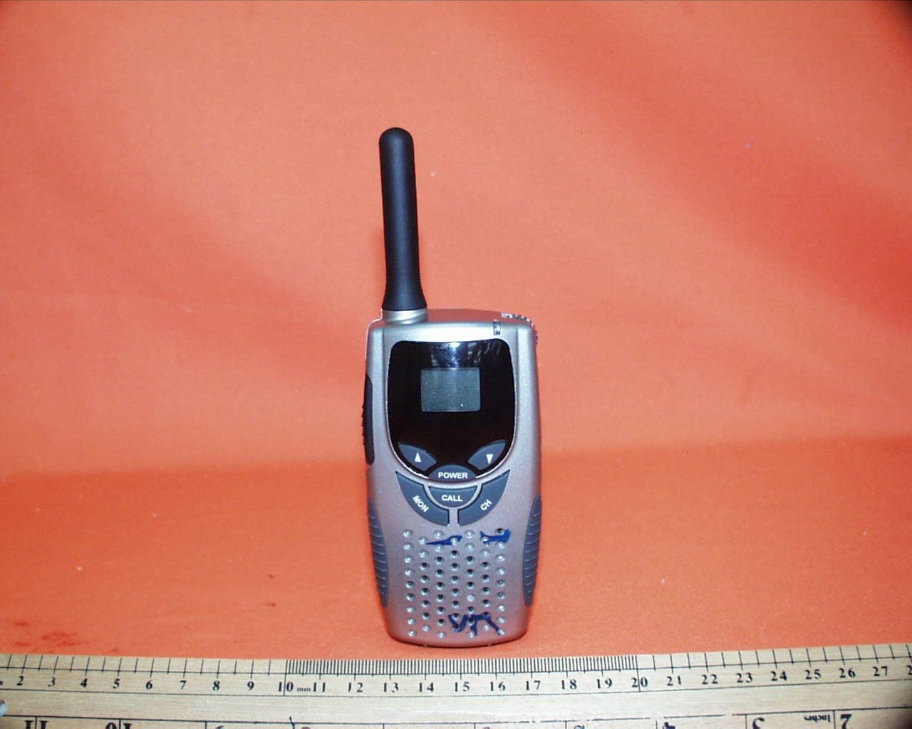
Jun 13, 200114-Channel FRS Transceiver
Equipment Class
FRF - Part 95 Family Radio Face Held Transmitter