OV6WSI002Narrow Band Transmitter
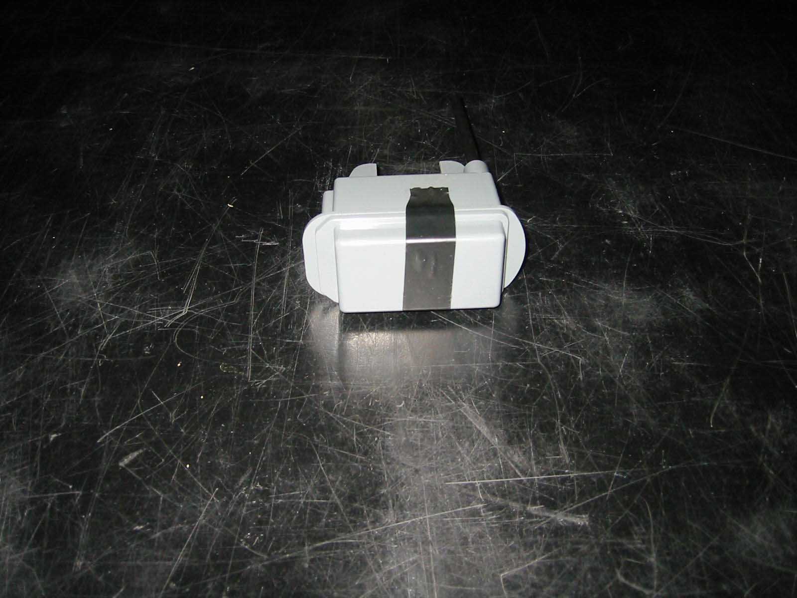
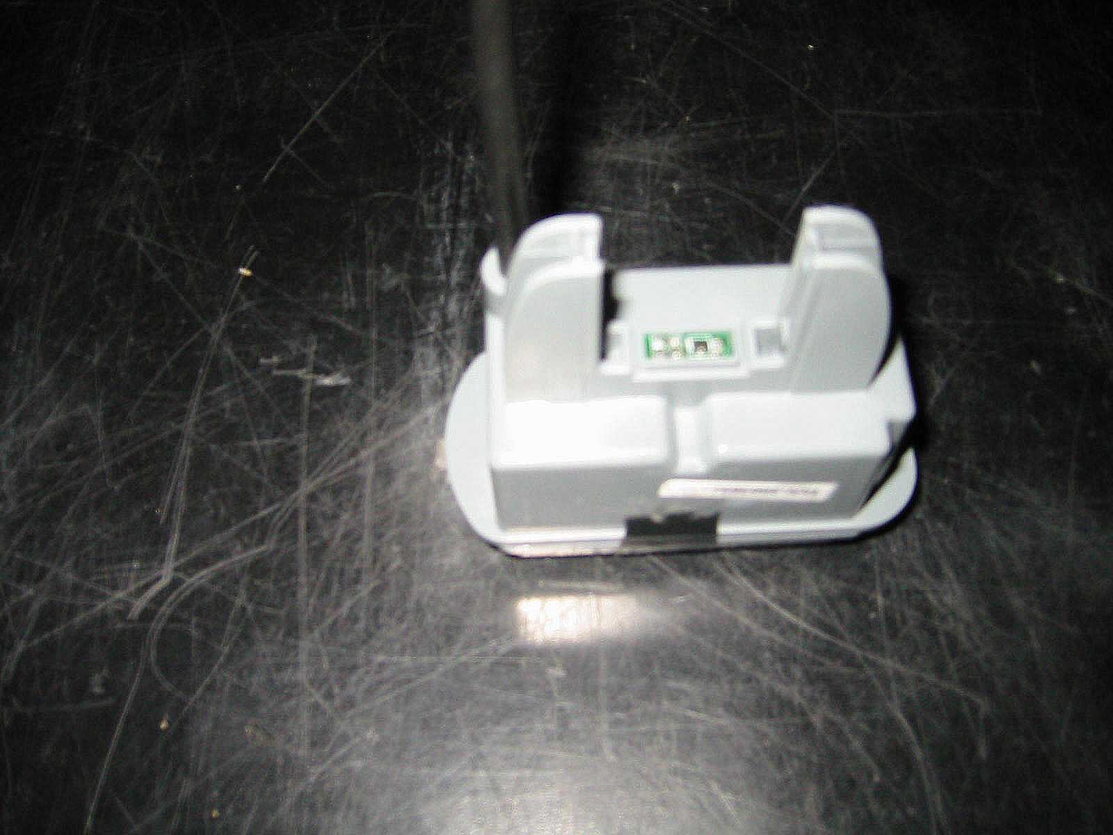
Wellspring International, Inc.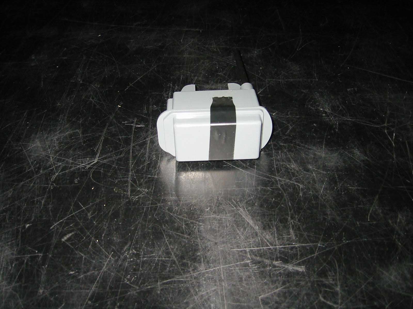
Click to zoom
Application Details
- Equipment Class
- DXX - Part 15 Low Power Communication Device Transmitter
- Date of Grant
- May 21, 2002
- Application Purpose
- Original Equipment
- Date of Application
- May 21, 2002
- Equipment Note
- Narrow Band Transmitter
- Frequency Range
- 915.00000000 - 915.00000000
- Country
- United States
Documents & Files
Document Text
Text extracted from the exhibit documents filed with the FCC. Open a document above to read the original.
Users Manual
3/11/02 USERS MANUAL WELLSPRING UTILITY METER TRANSMITTER Warning: Changes or modifications to this unit not expressly approved by the party responsible for compliance could void the user’s authority to operate the equipment. Wellspring Wireless Utility Services 830 Bear Tavern Road, Suite 301 Ewing, NJ 08628 Office: 609.530.1990 Fax:609.530.1991 www.wellspringwireless.com FCC ID: OV6WSI002 This device complies with part 15 of the FCC Rules: Operation is subject to the following conditions: (1) This device many not cause harmful interference, and (2) This device must accept any interference received, Including interference that may cause undesired operation INSTALLATION NOTE: There are no user serviceable parts or adjustments inside this transmitter The Utility Meter Transmitter is designed to be installed onto the Wellspring water meter module after installation of the module by a licensed plumber. The Transmitter should be carefully inserted onto the module and the retention clip securely attached. After installation, each transmitter location and serial number must be recorded for the billing database.
Test Report
Emissions Testing Performed on the Saar Associates Narrow Band Transmitter Model: WSI002 To FCC Part 15 Subpart C, 15.249 Date of Test: February 27, 2002 Report Date: March 29, 2002 Page 1 of 18 Report Number: 3019852 Contact: David Saar All services undertaken are subject to the following general policy: Reports are submitted for exclusive use of the client to whom they are addressed. Their significance is subject to the adequacy and representative character of the samples and to the comprehensiveness of the tests, examinations or surveys made. No quotations from reports or use of Intertek Testing Services NA Inc. name is permitted except as expressly authorized by Intertek Testing Services NA Inc. in writing. This report must not be used to claim product endorsement by NVLAP, NIST or any other agency of the U.S. Government. Intertek Testing Services NA, Inc. Part 15 Laboratory Measurements and ANSI C63.4-1992Report Number: 3019852 Revision March 24, 2000Page 2 of 17 This document may not be reproduced except in its entirety without written permission from ITS. Table of Contents TABLE OF CONTENTS ................................................................................................................................................ 2 I – INTRODUCTION AND SUMMARY........................................................................................................................ 3 II – TECHNICAL REQUIREMENTS ............................................................................................................................. 4 15.1SCOPE.............................................................................................................................................................. 4 15.27SPECIAL ACCESSORIES ............................................................................................................................... 4 15.33 FREQUENCY RANGE OF MEASUREMENT................................................................................................ 6 15.35MEASUREMENT DETECTOR FUNCTIONS AND BANDWIDTH.............................................................. 6 15.201 CERTIFICATION............................................................................................................................................. 6 15.203 ANTENNA REQUIREMENTS........................................................................................................................ 6 15.205 RESTRICTED BANDS OF OPERATION....................................................................................................... 6 15.207 CONDUCTED LIMITS.................................................................................................................................... 7 15.209 RADIATED EMISSION LIMITS; GENERAL REQUIREMENTS .................................................................. 7 15.249 OPERATION IN THE BANDS 902-928 MHZ, 2400-2483.5 MHZ, 5725-5875 MHZ, AND 24.0-24.25 GHZ ..8 III - ATTESTATION....................................................................................................................................................... 9 IV - SITE DESCRIPTION AND MEASUREMENT EQUIPMENT.............................................................................. 10 V – SUMMARY OF EQUIPMENT UNDER TEST ...................................................................................................... 12 VI - CONFIGURATION INFORMATION ................................................................................................................... 13 VII - CONFIGURATION PHOTOGRAPHS................................................................................................................. 14 VIII - SAMPLE CALCULATION................................................................................................................................. 16 IX - DATA TABLES .................................................................................................................................................... 17 Intertek Testing Services NA, Inc. Part 15 Laboratory Measurements and ANSI C63.4-1992Report Number: 3019852 Revision March 24, 2000Page 3 of 17 This document may not be reproduced except in its entirety without written permission from ITS. I – Introduction and Summary TO:Mr. David Saar FROM:Nicholas Abbondante, Compliance Engineer DATE:February 27, 2002 PROJECT #: 3019852 RE:Emissions testing of the Narrow Band Transmitter, Model: WSI002 On February 27, 2002 we tested the Narrow Band Transmitter, Model: WSI002 to determine if it was in compliance with the FCC Part 15, Subpart C, 15.249, “Operation within the bands 902- 928 MHz, 2400-2483.5 MHz, 5725-5875 MHz, and 24.0-24.25 GHz” requirements. A prototype version of the sample was received on 2/26/2002 in good condition. We found that the unit met the Part 15 requirements when tested as received. The following table summarizes the results of testing. TestPass/FailSection of FCC Rule s Section of Test Report Fundamental Field Strength Pass15.249Table 1 Harmonic Emissions Pass15.249Table 1 Restricted Band & Spurious Emissions Pass 15.249, 15.205 15.209 Table 1 In summary, this report confirms that the Narrow Band Transmitter, Model: WSI002 is compliant with the FCC Part 15, Subpart C, 15.249 requirements when production units conform to the initial sample. Please address all questions and comments concerning this report to Nicholas Abbondante, Compliance Engineer. Intertek Testing Services NA, Inc. Part 15 Laboratory Measurements and ANSI C63.4-1992Report Number: 3019852 Revision March 24, 2000Page 4 of 17 This document may not be reproduced except in its entirety without written permission from ITS. II – Technical Requirements 15.1 Scope The EUT is a telemetry transmitter which measures the flow of water in a flow sensor as well as the temperature of the water. A prototype of the was received on 2/26/2002 in good condition. 15.27 Special Accessories No special accessories …
Text truncated - open the document above for the full version.
Test Report
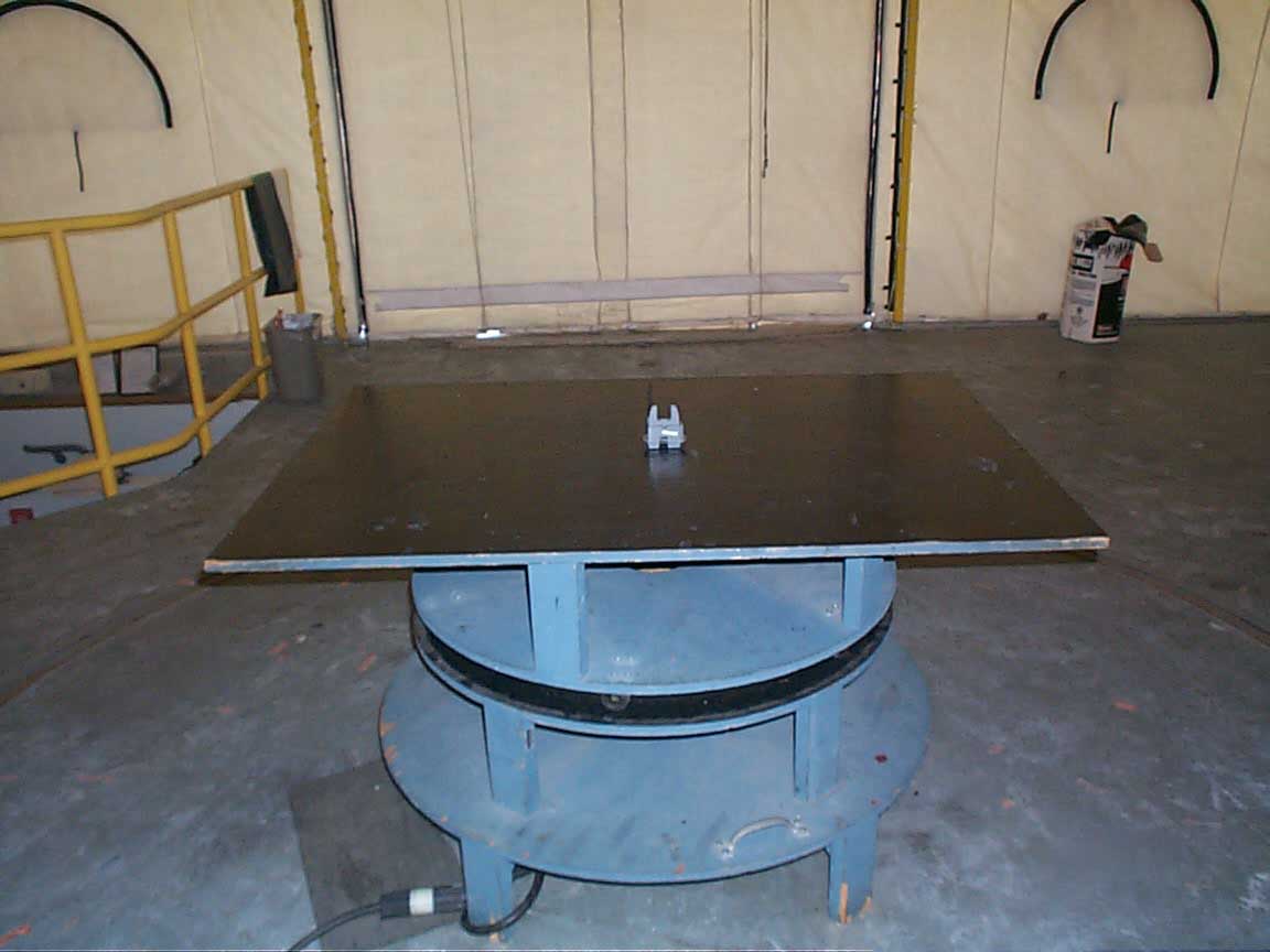
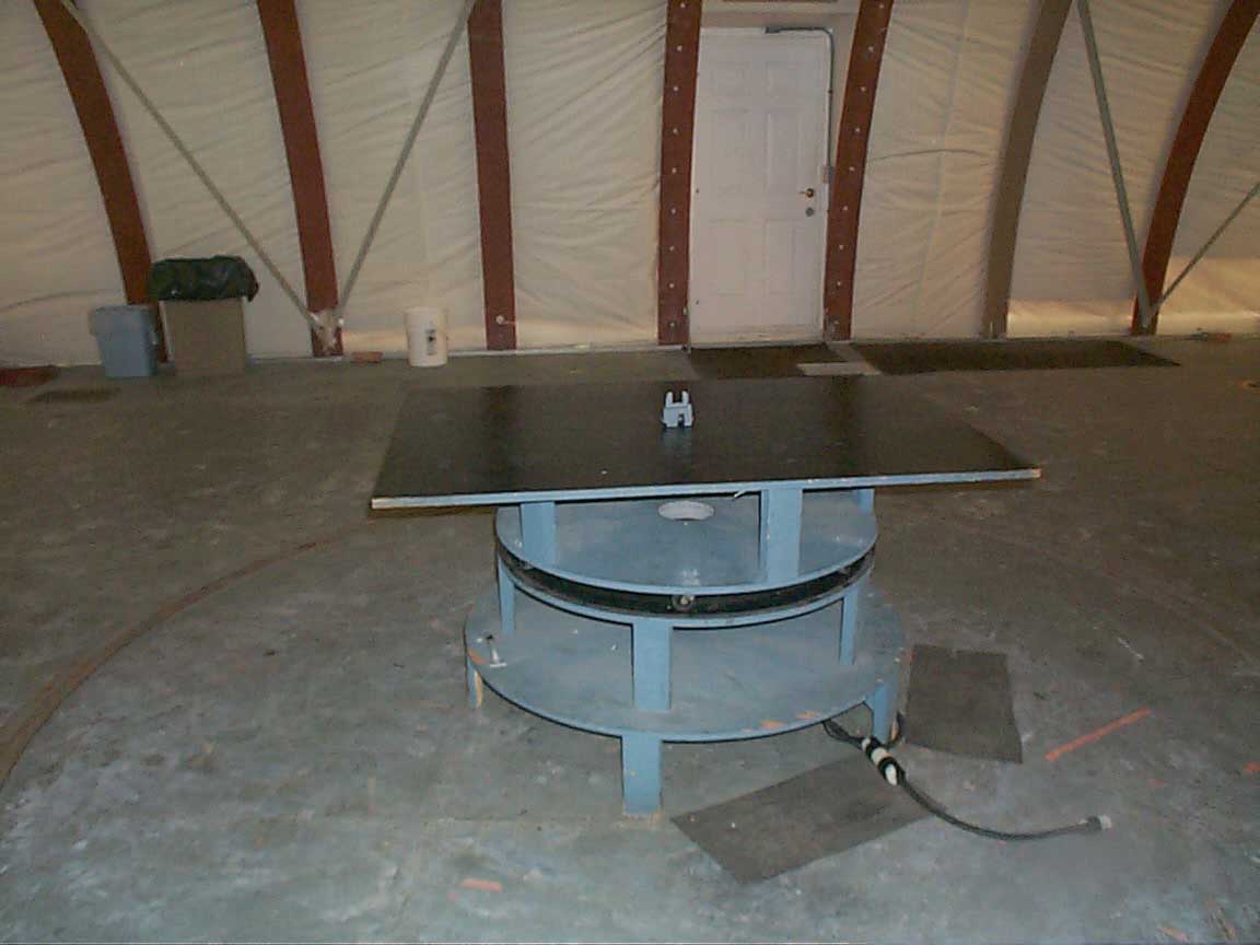
70 Codman Hill Road Boxborough MA 01719 Saar Associates, Inc., Model No. WSI002Date of Test: December 17, 2003 Report # 3019852A3FCC Part 15 Certification Equipment Under Test:Narrow Band Transmitter Model:WSI002 Serial No.:Proto1 FCC Identifier:OV6WSI002 Support Equipment: None, the EUT was operated in a standalone configuration. Cables: QTYDescriptionShield DescriptionHood DescriptionLength (m) None Test Equipment DescriptionManufacturerModelSerial #Cal Due High Freq Cable 40GhzMegaphaseTM40 K1K1 80CBL03011/11/2004 High Freq Cable 40GhzMegaphaseTM40 K1K1 197CBL02711/11/2004 Spectrum AnalyzerRohde & SchwartzFSEK-3010022505/26/2004 HORN ANTENNAEMCO31159512-463210/24/2004 Description of how the EUT was exercised during test The EUT was activated using fresh batteries. The transmitter was set to transmit an FSK modulated signal twice a second for 200 ms per pulse during testing. In normal usage, this 400 ms on time occurs once every 8 hours. Site Description Site 2C (Middle Site) is a 3m and 10m sheltered EMI measurement range located in a light commercial environment in Boxborough, Massachusetts. It meets the technical requirements of ANSI C63.4-1992 and CISPR 22:1993/EN 55022:1994 for radiated and conducted emission measurements. The shelter structure is entirely fiberglass and plastic, with outside dimensions of 33 ft x 57 ft. The structure resembles a quonset hut with a center ceiling height of 16.5 ft. The testing floor is covered by a galvanized sheet metal groundplane that is earth-grounded via copper rods around the perimeter of the site. The joints between individual metal sheets are bridged with a 2 inch wide metal strips to provide low RF impedance contact throughout. The sheets of metal are screwed in place with stainless steel, round-head screws every three inches. Site illumination and HVAC are provided from beneath the ground reference plane through flush entry ports, the port covers are electically bonded to the ground plane. A flush metal turntable with 12 ft. diameter and 5000 lb. load capacity is provided for floor-standing equipment. A wooden table 80 cm high is used for table-top equipment. The turntable is electrically 70 Codman Hill Road Boxborough MA 01719 Saar Associates, Inc., Model No. WSI002Date of Test: December 17, 2003 Report # 3019852A4FCC Part 15 Certification connected to the ground plane with three copper straps. The straps are connected to the turntable at the center of it with ground braid. It is copper strap is directly connected to the groundplane at the edges of the turntable. The turntable is located on the south end of the structure and the antennas are mounted 3 and 10 meters away to the north. The antenna mast is a non-conductive with remote control of antenna height and polarization. The antenna height is adjustable from 1 to 4 meters. All final radiated emission measurements are performed with the testing personnel and measurement equipment located below the ground reference plane. The site has a full basement underneath the turntable where support equipment may be remotely located. Operation of the antenna, turntable and equipment under test is controlled by remote controls that manipulate the antenna height and polarization and with a turntable control. Test personnel are located below the elipse when measurements are performed, however the site maintains the ability of having personnel manipulate cables while monitoring test equipment. Ambient radiated emissions are 6 dB or more below the relevant FCC emission limits. AC mains power is brought to the equipment under test through a power line filter, to remove ambient conducted noise. 50 Hz (240 VAC single phase), 60 Hz power (120 VAC single phase, 208 VAC three phase), and 60 Hz (480 VAC three phase) are available. Conducted emission measurements are performed with a Line Impedance Stabilization Network (LISN) or Artificial Mains Network (AMN) bonded to the ground reference plane. A removable vertical groundplane (2 meter X 2 meter area) is used for line- conducted measurements for table top equipment. The vertical groundplane is electrically connected to the reference groundplane. Config Photos 70 Codman Hill Road Boxborough MA 01719 Saar Associates, Inc., Model No. WSI002Date of Test: December 17, 2003 Report # 3019852A5FCC Part 15 Certification Results Company:Tested by: Model #: Serial #:Proto1 Location: Project #: Pressure:1001 mb Detector: Date: 12/17/03Temp:16c Antenna: Standard: Humidity:36% PreAmp: Class: None Group: None Cable(s): Notes:Distance:3meters Ant.AntennaCablePre-ampDistance Pol.FrequencyReadingFactorLossFactorFactorNetLimitMargin (V/H)MHzdB(uV)dB(1/m)dBdBdBdB(uV/m)dB(uV/m)dB H1830.00041.128.53.819.40.054.074.0-6.1 V2745.000 V3660.000 V4575.000 Noise Floor Reading; No emission to measure peak value Noise Floor Reading; No emission to measure peak value Noise Floor Reading; No emission to measure peak value Radiated Emissions / Interference Table: 1 Saar Associates, Inc.Nicholas Abbondante Narrow Band TransmitterEMI Site 2 3019852R&S FSEK30 None RBW 1 MHz, VBW 3 MHz, Detector +Peak HORN1 FCC Part 15 CPRE8 CBL030, CBL 027 The following is how net radiated field strength readings were determined: NF = RF + AF + CF - PF - AVF - DF Where, NF = Net Reading in dBμV/m RF = Reading from receiver in dBμV AF = Antenna Correction Factor in dB(1/m) CF = Cable Correction Factor in dB PF = Pre-Amplifier Correction Factor in dB AVF = Duty Cycle Correction Factor in dB (only if applicable) DF = Distance Factor in dB (using 20 dB/decade unless otherwise specified) To convert from dBμV/m to μV/m or mV/m the following was used: UF = 10 (NF / 20) Where, UF = Net Reading in μV/m Example: NF = RF + AF + CF - PF - AVF - DF = 62.9 + 13.7 + 2.1 - 16.1 - 0.0 - 10.5 = 52.1 dBμV/m UF = 10 (52.1 dBμV / 20) = 403 μV/m
Test Report
70 Codman Hill Road Boxborough MA 01719 Saar Associates, Inc., Model No. WSI002Date of Test: December 17, 2003 Report # 3019852A3FCC Part 15 Certification Equipment Under Test:Narrow Band Transmitter Model:WSI002 Serial No.:Proto1 FCC Identifier:OV6WSI002 Support Equipment: None, the EUT was operated in a standalone configuration. Cables: QTYDescriptionShield DescriptionHood DescriptionLength (m) None Test Equipment DescriptionManufacturerModelSerial #Cal Due High Freq Cable 40GhzMegaphaseTM40 K1K1 80CBL03011/11/2004 High Freq Cable 40GhzMegaphaseTM40 K1K1 197CBL02711/11/2004 Spectrum AnalyzerRohde & SchwartzFSEK-3010022505/26/2004 HORN ANTENNAEMCO31159512-463210/24/2004 Description of how the EUT was exercised during test The EUT was activated using fresh batteries. The transmitter was set to transmit an FSK modulated signal twice a second for 200 ms per pulse during testing. In normal usage, this 400 ms on time occurs once every 8 hours. Site Description Site 2C (Middle Site) is a 3m and 10m sheltered EMI measurement range located in a light commercial environment in Boxborough, Massachusetts. It meets the technical requirements of ANSI C63.4-1992 and CISPR 22:1993/EN 55022:1994 for radiated and conducted emission measurements. The shelter structure is entirely fiberglass and plastic, with outside dimensions of 33 ft x 57 ft. The structure resembles a quonset hut with a center ceiling height of 16.5 ft. The testing floor is covered by a galvanized sheet metal groundplane that is earth-grounded via copper rods around the perimeter of the site. The joints between individual metal sheets are bridged with a 2 inch wide metal strips to provide low RF impedance contact throughout. The sheets of metal are screwed in place with stainless steel, round-head screws every three inches. Site illumination and HVAC are provided from beneath the ground reference plane through flush entry ports, the port covers are electically bonded to the ground plane. A flush metal turntable with 12 ft. diameter and 5000 lb. load capacity is provided for floor-standing equipment. A wooden table 80 cm high is used for table-top equipment. The turntable is electrically 70 Codman Hill Road Boxborough MA 01719 Saar Associates, Inc., Model No. WSI002Date of Test: December 17, 2003 Report # 3019852A4FCC Part 15 Certification connected to the ground plane with three copper straps. The straps are connected to the turntable at the center of it with ground braid. It is copper strap is directly connected to the groundplane at the edges of the turntable. The turntable is located on the south end of the structure and the antennas are mounted 3 and 10 meters away to the north. The antenna mast is a non-conductive with remote control of antenna height and polarization. The antenna height is adjustable from 1 to 4 meters. All final radiated emission measurements are performed with the testing personnel and measurement equipment located below the ground reference plane. The site has a full basement underneath the turntable where support equipment may be remotely located. Operation of the antenna, turntable and equipment under test is controlled by remote controls that manipulate the antenna height and polarization and with a turntable control. Test personnel are located below the elipse when measurements are performed, however the site maintains the ability of having personnel manipulate cables while monitoring test equipment. Ambient radiated emissions are 6 dB or more below the relevant FCC emission limits. AC mains power is brought to the equipment under test through a power line filter, to remove ambient conducted noise. 50 Hz (240 VAC single phase), 60 Hz power (120 VAC single phase, 208 VAC three phase), and 60 Hz (480 VAC three phase) are available. Conducted emission measurements are performed with a Line Impedance Stabilization Network (LISN) or Artificial Mains Network (AMN) bonded to the ground reference plane. A removable vertical groundplane (2 meter X 2 meter area) is used for line- conducted measurements for table top equipment. The vertical groundplane is electrically connected to the reference groundplane. Config Photos 70 Codman Hill Road Boxborough MA 01719 Saar Associates, Inc., Model No. WSI002Date of Test: December 17, 2003 Report # 3019852A5FCC Part 15 Certification Results Company:Tested by: Model #: Serial #:Proto1 Location: Project #: Pressure:1001 mb Detector: Date: 12/17/03Temp:16c Antenna: Standard: Humidity:36% PreAmp: Class: None Group: None Cable(s): Notes:Distance:3meters Ant.AntennaCablePre-ampDistance Pol.FrequencyReadingFactorLossFactorFactorNetLimitMargin (V/H)MHzdB(uV)dB(1/m)dBdBdBdB(uV/m)dB(uV/m)dB H1830.00041.128.53.819.40.054.074.0-6.1 V2745.000 V3660.000 V4575.000 Noise Floor Reading; No emission to measure peak value Noise Floor Reading; No emission to measure peak value Noise Floor Reading; No emission to measure peak value Radiated Emissions / Interference Table: 1 Saar Associates, Inc.Nicholas Abbondante Narrow Band TransmitterEMI Site 2 3019852R&S FSEK30 None RBW 1 MHz, VBW 3 MHz, Detector +Peak HORN1 FCC Part 15 CPRE8 CBL030, CBL 027 The following is how net radiated field strength readings were determined: NF = RF + AF + CF - PF - AVF - DF Where, NF = Net Reading in dBμV/m RF = Reading from receiver in dBμV AF = Antenna Correction Factor in dB(1/m) CF = Cable Correction Factor in dB PF = Pre-Amplifier Correction Factor in dB AVF = Duty Cycle Correction Factor in dB (only if applicable) DF = Distance Factor in dB (using 20 dB/decade unless otherwise specified) To convert from dBμV/m to μV/m or mV/m the following was used: UF = 10 (NF / 20) Where, UF = Net Reading in μV/m Example: NF = RF + AF + CF - PF - AVF - DF = 62.9 + 13.7 + 2.1 - 16.1 - 0.0 - 10.5 = 52.1 dBμV/m UF = 10 (52.1 dBμV / 20) = 403 μV/m
Contact Information
Applicant
Wade W Smith(CEO)
Technical Contact
Saar Associates, Inc.David Saar
[email protected]609-818-0860
37 Todd Ridge Road · Titusville, New Jersey · United States
Non-Technical Contact
Wellspring International, Inc.Wade Smith
609-530-1990
Test Firm
Intertek Testing Services NA Inc.Roland Gubisch
Technical Specifications
| # | Rule Parts | Frequency Range | Power Output |
|---|---|---|---|
| 1 | 15C | 915 MHz - 915 MHz | - |
Other Applications from Wellspring International, Inc.
OV6WMS001
Mar 02, 2000Water flow and temperature measurement transmitter
Equipment Class
DXX - Part 15 Low Power Communication Device Transmitter