OVS-APOSPOS System
Senor Tech Co Ltd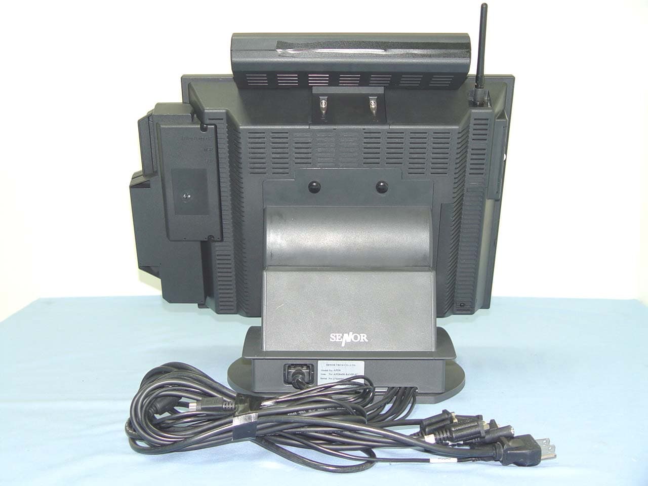
Click to zoom
Application Details
- Equipment Class
- DTS - Digital Transmission System
- Date of Grant
- Jun 28, 2007
- Application Purpose
- Original Equipment
- Date of Application
- Jun 28, 2007
- Equipment Note
- POS System
- Frequency Range
- 2412.00000000 - 2462.00000000
- Company
- Senor Tech Co Ltd
- Country
- Taiwan
Documents & Files
Document Text
Text extracted from the exhibit documents filed with the FCC. Open a document above to read the original.
Users Manual
I I w w n n A A P P O O S S Quick Reference APOS XXX X=0-9 A-Z OR None S S e e n n o o r r T T e e c c h h C C o o . . , , L L t t d d . . http://www.senortech.com S S e e n n o o r r T T e e c c h h C C o o . . , , L L t t d d . . APOS Quick Reference 1 1. Features Senor’s APOS, an advanced POS terminal, incorporates the all-in-one concept. Designed to be a multi-functional compact and reliable POS terminal, Senor’s APOS can optionally integrate with Customer Display, Magnetic Card Reader, Smart Card Reader, I-Button, Finger Print, RFID, Keyboard and other I/O devices. Senor’s APOS unique and intelligent design is suitable for a wide range of applications including: Hospitality Retail Kiosk Application Note:(1) Optional devices such as VESA standard mounting bracket or arm, Customer Display, Magnetic Card Reader, Smart Card Reader, I-Button, Finger Print, RFID and other I/O devices are only available at an additional cost. 2. Unpacking The following items are Included when you purchase this product. If any items are damaged or missing, contact your dealer for assistance. Rating: 100-240VAC 50/60Hz 1.5A AntennaBattery (Optional Part) (Optional Part) APOS Driver Power Cord IR Keyboard (Optional Part) Quick Reference SENOR TECH CO., LTD www.senortech.com Quick Reference S S e e n n o o r r T T e e c c h h C C o o . . , , L L t t d d . . APOS Quick Reference 2 3. Configuration Front View Card Reader Interface Cover EXT USB X 2 VFD Interface Cover HDD Cover Power Switch Push ON Button Battery Cover Indicator Antenna Back View (1)- Base and I/O cables PS2 Loop IR K/B PS2 K/B I/O Cables x 7 APOS Unit Mic In Audio COM6 COM5 COM4 COM3 Back View (2)- Connector locations APOS DC Power LAN PS2 K/B COM6 CF Card Audio Out MIC EXT USB EXT VGA COM3 COM4 COM5 S S e e n n o o r r T T e e c c h h C C o o . . , , L L t t d d . . APOS Quick Reference 3 Red - AC Input OK Blue - Booting Mode Blue Flash - Battery Mode 4. Power On The Power Switch is located behind the left hand side of the LCD front panel. Ensure it is switched to “ON” position (Stand-by) before use. Push the ON button which is the middle bottom (SENOR Logo indicator) on the front of the LCD. When connected to an AC source, the LED lamp will illuminate automatically. The unit’s status can be determined by the LED lamp’s colour. Turn on the unit by pressing the Push ON Button. To turn off the unit press and hold the button for 3 seconds. Indicator modes as follows: 5. HDD Replacement To remove the HDD, use a screwdriver to loosen the screws on the left side of the panel. Caution: A. Both sides of the Hard Disk should be installed with slide tracks. B. To install or to withdraw HDD, the power must be switched off. 6. Battery Replacement To remove the battery, remove the screws under the left side panel. The battery will last for 35min. Battery recharge should take approximately 2 hours, (the battery recharge can proceed even in Stand-by mode). Remove the battery from the APOS if it will not be used for an extended period. With Sleep Mode function, Senor’s APOS can support Low Battery Suspend to Disk. S S e e n n o o r r T T e e c c h h C C o o . . , , L L t t d d . . APOS Quick Reference 4 Caution: Do not leave the power switch in the ON position (Stand-by) with the AC power source switched ODD or Disconnected. In this situation the battery will continue to supply power to the unit, causing it to discharge over a period of time. If the AC power source is to be removed for a period greater than 24 hours (e.g. Storage, shipping) ensure the APOS power switch is in the OFF position to avoid damage to the battery. 7. VFD Replacement Take the cover off and insert the VFD set, use two M3 screws to secure the VFD onto the unit. VFD I/O port is located on Com1. Caution: To install or to withdraw VFD, power must be switched off. S S e e n n o o r r T T e e c c h h C C o o . . , , L L t t d d . . APOS Quick Reference 5 8. Card Reader Replacement Take the cover off and insert the Card Reader module. Use two M3 screws to secure the Card Reader into the unit. If a Keyboard Wedge Device is not installed in the unit, install the short plug to ensure the keyboard device will operate. Caution: To install or to withdraw Card Reader, power must be switched off. 9. LCD Viewing Angle Adjustment In order to accommodate various operator preferences and lighting conditions, Senor’s APOS is equipped with an operator tilt mechanism. Two buttons are located behind the middle left-hand edge of the operator LCD. The uppermost button tilts the screen UP while the lower tilts the screen DOWN. The tilt movement is limited to a minimum of 30 degrees and a maximum of 70 degrees. To adjust the angle, press and hold the UP or DOWN button as required until the optimum viewing angle is found or when the LCD reaches its maximum or minimum limit. DOWN UP S S e e n n o o r r T T e e c c h h C C o o . . , , L L t t d d . . APOS Quick Reference 6 10. Mounting The APOS is designed to be fitted with a desk stand base unit or with a VESA standard mounting bracket or arm (75mm X 75mm; 100mm X 100mm) if required. 10.1 Unscrew the two thumbscrews securing the base unit to the LCD panel. 10.2 Separate the LCD panel from the base unit by lifting the LCD panel. 10.3 Use four M4 screws to secure the APOS LCD panel on to any VESA standard mounting bracket or arm USE four M4 Screws S S e e n n o o r r T T e e c c h h C C o o . . , , L L t t d d . . APOS Quick Reference 7 NOTE: The length of screws must not exceed 8mm. 11. Additional Devices: Driver Installation After installing Win98 SE/ME/2000/SP, the system still needs additional device drivers installed, which are located on the Driver CD. The drivers are as follows: 11.1 M/B Chipset Driver. 11.2 Install the LAN Chip Driver from enclosed driver CD. 11.3 Install the touch driver from enclosed driver CD. The port of Touch Controller is located on the Com2. Mounting by four M4 screws S S e e n n o o r r T T e e c c h h C C o o . . , , L L t t d…
Text truncated - open the document above for the full version.
Cover Letter(s)
Date: 2007/6/11 Compliance Certification Services Certification Division 561F Monterey Road Morgan Hill, CA 95037 To whom it may concern: We, the undersigned, hereby authorize the Taiwan office of Compliance Engineering Services, Inc., d.b.a. Compliance Certification Services and hereafter referred to as CCS TW, to act on our behalf in all manners relating to application for equipment authorization, including signing of all documents relating to these matters. Any and all acts carried out by CCS TW on our behalf shall have the same effect as acts of our own. We, the undersigned, hereby certify that we are not subject to a denial of federal benefits, that includes FCC benefits, pursuant to Section 5301 of the Anti-Drug Abuse Act of 1988, 21 U.S.C. 853(a). In authorizing CCS TW as our agent, we still recognize that we are responsible to: a) Comply with the relevant provisions of the certification program; b) Make all necessary arrangements for the conduct of the evaluation, including provision for examining documentation and access to all areas, records (including internal audit reports) and personnel for the purposes of evaluation (e.g. testing, inspection, assessment, surveillance, reassessment) and resolution of complaints; c) Make claims regarding certification only in respect of the scope for which certification has been granted; d) Do not use our product certification in such a manner as to bring the Certification Division into disrepute and not make any statement regarding our product certification which the Certification Division may consider misleading or unauthorized; e) Upon suspension or cancellation of certification, discontinue use of all advertising matter that contains any reference thereto and return any certification documents as required by the Certification Division; f) Use certification only to indicate the products are certified as being in conformity with specified standards; g) Endeavor to ensure that no certificate or report nor any part thereof is used in a misleading manner; h) Ensure that any reference to our product certification in communication media such as documents, brochures or advertising, complies with the requirements of the Certification Division; i) Keep a record of all complaints made known to the us relating to the product compliance with requirements of the relevant standard and to make these records available to the Certification Division when requested; j) Take appropriate action with respect to such complaints and any deficiencies found in products or services that affect compliance with the requirements for certification; k) Document the actions taken. This authorization is valid until further written notice from the applicant. Sincerely Yours, --------------------------------- REMARK: 1. This authorization letter will be sent along with your application when filing with the Certification Division. 2. Please follow the format and type it on company letterhead and send original to us.
Cover Letter(s)
June 12, 2007 Federal Communications Commission Authorization and Evaluation Division FCC ID: Confidentiality Request Pursuant to Sections 0.457 and 0.459 of the Commission’s Rules, the Applicant hereby requests confidential treatment of information accompanying this Application as outlined below: 1. Schematics 2. Operational Description 3. Block Diagram The above materials contain trade secrets and proprietary information not customarily released to the public. The public disclosure of these matters might be harmful to the Applicant and provide unjustified benefits to its competitors. The Applicant understands that pursuant to Rule 0.457, disclosure of this Application and all accompanying documentation will not be made before the date of the Grant for this application. Sincerely, -------------------------------
Cover Letter(s)
http://mail.google.com/mail/?ik=2a69a1bf8a&view=cv&search=inbox&th=11355f0c73491ada&ww=1131&cvap=10&qt=&zx=7a4ku9aqqsp9 SENOR TECH CO., LTD., FCC ID: OVS-APOS, Assessment NO.: AN07T6916, Notice#1 Inbox Reply from "[email protected]" <[email protected]> hide details Jun 19 (3 days ago) to [email protected] cc [email protected] date Jun 19, 2007 9:26 PM subject SENOR TECH CO., LTD., FCC ID: OVS-APOS, Assessment NO.: AN07T6916, Notice#1 Dear CCS TW, The application review is complete. Please respond to the following 3 items so the application can be sent for certification. If you have questions, please ask. Q1: User manual page 8. Please remove the statement referencing fixed point-to-point installation. This is not a fixed point to point device. Because this is a mobile device, please revise the manual to include: "The antenna(s) used for this device must be installed to provide a separation distance of at least 20 cm from all persons and must not be co-located or operating in conjunction with any other antenna or transmitter." Q2: The measurement results on page 46 of the test report exceed the limits of FCC 15.209. If the emissions are associated with the wireless transmitter, then the results are non-compliannt. The limits shown are those for a Class A digital device. If the emissions reported are from the digital device and not from the transmitter, then this is acceptable, but the test report should include an explanation about the emissions. All emissions related to the transmitter must comply with the 15.209 limits. Q3: The label submitted with the FCC Logo is suitable only for Class B digital devices. If the emissions exceed the Class B limits, then the section of the label with the FCC Logo, "For home or office use" etc may not be used and must be removed. The other statement on the label with "This device complies with.." is the correct label for both the wireless device and for a Class A digital device and should remain. Best regards, Tim Dwyer CCS TCB Reviewer The items indicated above must be submitted before processing can continue on the above referenced application. Failure to provide the requested information within 30 days of the original e-mail date may result in application dismissal and forfeiture of the filing fee. Also, please note that partial responses increase processing time and should not be submitted. Any questions about the content of this correspondence should be directed to the e-mail address listed below the name of the sender. Reply Reply to all Forward Invite [email protected] to Gmail Reply from "gina.lo" <[email protected]> hide details 1:08 am (19 hours ago) to [email protected] date Jun 22, 2007 1:08 AM subject Re:SENOR TECH CO., LTD., FCC ID: OVS-APOS, Assessment NO.: AN07T6916, Notice#1 http://mail.google.com/mail/?ik=2a69a1bf8a&view=cv&...355f0c73491ada&ww=1131&cvap=10&qt=&zx=7a4ku9aqqsp9 (1 of 3)6/22/2007 8:18:52 PM http://mail.google.com/mail/?ik=2a69a1bf8a&view=cv&search=inbox&th=11355f0c73491ada&ww=1131&cvap=10&qt=&zx=7a4ku9aqqsp9 Dear Sir, Please see my reply, thank you. Best Regards, Gina <tim.dwyer@ccsemc. com> 2007/06/20 09:26 AM <[email protected]> <[email protected]> SENOR TECH CO., LTD., FCC ID: OVS-APOS, Assessment NO.: AN07T6916, Notice#1 Dear CCS TW, The application review is complete. Please respond to the following 3 items so the application can be sent for certification. If you have questions, please ask. Q1: User manual page 8. Please remove the statement referencing fixed point-to- point installation. This is not a fixed point to point device. Because this is a mobile device, please revise the manual to include: "The antenna(s) used for this device must be installed to provide a separation distance of at least 20 cm from all persons and must not be co-located or operating in conjunction with any other antenna or transmitter." Ans: Please see page 9 of the revised User manual. Q2: The measurement results on page 46 of the test report exceed the limits of FCC 15.209. If the emissions are associated with the wireless transmitter, then the results are non-compliannt. The limits shown are those for a Class A digital device. If the emissions reported are from the digital device and not from the transmitter, then this is acceptable, but the test report should include an explanation about the emissions. All emissions related to the transmitter must comply with the 15.209 limits. Ans: Regarding to the RF module built in the EUT which used in a Class A environment, we have performed some test to confirm the emission source of EUT. Two type of test was performed as below: 1. Turn on the EUT with RF function, emission measurement from 30MHz to 1GHz was measured in vertical and horizontal polarization as attached result. 2. Turn off the RF function, however, the EUT still work in typical operation. The spurious emission were measured again as above. The data were also attached. To compare the data between EUT with and without RF function, we can verify the emission are dominate by digital devices not the RF block. http://mail.google.com/mail/?ik=2a69a1bf8a&view=cv&...355f0c73491ada&ww=1131&cvap=10&qt=&zx=7a4ku9aqqsp9 (2 of 3)6/22/2007 8:18:52 PM http://mail.google.com/mail/?ik=2a69a1bf8a&view=cv&search=inbox&th=11355f0c73491ada&ww=1131&cvap=10&qt=&zx=7a4ku9aqqsp9 Hope this information can identify the source of emission. It will be appreciated to have your opinion to clarify this issue. Q3: The label submitted with the FCC Logo is suitable only for Class B digital devices. If the emissions exceed the Class B limits, then the section of the label with the FCC Logo, "For home or office use" etc may not be used and must be removed. The other statement on the label with "This device complies with.." is the correct label for both the wireless device and for a Class A digital device and should remain. Ans: Please see page 9 of the revised label. - Show quoted text - 6 attachments — Download all attachments APOS…
Text truncated - open the document above for the full version.
External Photos
Compliance Certification Services Inc. Report No.: 70319002 Date of Issue: June 14, 2007 Page 1 Total Page: 16 Rev. 00 EXTERNAL PHOTOGRAPHS OF EUT Compliance Certification Services Inc. Report No.: 70319002 Date of Issue: June 14, 2007 Page 2 Rev.00 Compliance Certification Services Inc. Report No.: 70319002 Date of Issue: June 14, 2007 Page 3 Rev.00
Internal Photos
Compliance Certification Services Inc. Report No.: 70319002 Date of Issue: June 14, 2007 Page 4 Rev.00 INTERNAL PHOTOGRAPHS OF EUT Compliance Certification Services Inc. Report No.: 70319002 Date of Issue: June 14, 2007 Page 5 Rev.00 Compliance Certification Services Inc. Report No.: 70319002 Date of Issue: June 14, 2007 Page 6 Rev.00 Compliance Certification Services Inc. Report No.: 70319002 Date of Issue: June 14, 2007 Page 7 Rev.00 Compliance Certification Services Inc. Report No.: 70319002 Date of Issue: June 14, 2007 Page 8 Rev.00 Compliance Certification Services Inc. Report No.: 70319002 Date of Issue: June 14, 2007 Page 9 Rev.00 Compliance Certification Services Inc. Report No.: 70319002 Date of Issue: June 14, 2007 Page 10 Rev.00 Compliance Certification Services Inc. Report No.: 70319002 Date of Issue: June 14, 2007 Page 11 Rev.00 Compliance Certification Services Inc. Report No.: 70319002 Date of Issue: June 14, 2007 Page 12 Rev.00 Compliance Certification Services Inc. Report No.: 70319002 Date of Issue: June 14, 2007 Page 13 Rev.00 Module Compliance Certification Services Inc. Report No.: 70319002 Date of Issue: June 14, 2007 Page 14 Rev.00 Compliance Certification Services Inc. Report No.: 70319002 Date of Issue: June 14, 2007 Page 15 Rev.00 Battery Compliance Certification Services Inc. Report No.: 70319002 Date of Issue: June 14, 2007 Page 16 Rev.00 Dipole Antenna
Parts List/Tune Up Info
1 A PPROVAL SHEET MODEL : WGT001 DESCRIPTION :單頻外掛天線 wgt P/N : WG001APDI01A C USTOMER P/N : DATE : 25 JUL.,2005 Manager Chief Engineer 精乘科技股份有限公司 桃園縣平鎮市民族路雙連二段 118 巷 51 弄 20 號 Well Green Technology Co., Ltd. No. 20, Alley51 ,Lane 118,ShuangLian Sec.2,Mintzu Rd., PingJen City, TaoYuan Hsien, Taiwan, R.O.C TEL: +886-3-420-6428 ; FAX: +886-3-420-6418 Check Responser w g t 星 喬 科 技 股 份 有 限 公 司 2 Wgt001 001-ACE-AWG01-A WG001APDI01A Notes Qty 1 111 Specification 1 432 No. RUBBER TUBE SMA MALE Reverse UP CONNECT DOWN CONNECT 一、成品圖 3 二、 Antenna Testing Conditions: Testing set up: HORN Standard Antenna R3767CG Network Analyzer Rotator Controller Radiation Pattern Testing - Anechoic Chamber A ntenna 90 ∘ 600 cm clockwise 4 三、電氣特性(Antenna Electricity Characteristics): 1. Return Loss 精乘科技股份有限公司 Well Green Technology CO. , Ltd Frequency Band : 2.4 ~ 2.5GHz Date : 25 JUL.,2005 Return Loss Antenna Center freg. @MHz BW @MHz 2.4GHz 2.45GHz 2.5GHz 外掛天線 2450 -10.56 -15.26 -13.10 P/N : WG001APDI01A 5 2. VSWR 精乘科技股份有限公司 Well Green Technology CO. , Ltd Frequency Band : 2.4 ~ 2.5GHz Date : 25 JUL.,2005 VSWR Antenna Center freg. @MHz BW @MHz 2.4GHz 2.45GHz 2.5GHz 外掛天線 2450 1.83 1.41 1.57 P/N : WG001APDI01A 6 3. Smith Chart 精乘科技股份有限公司 Well Green Technology CO. , Ltd Frequency Band : 2.4 ~ 2.5GHz Date : 25 JUL.,2005 P/N : WG001APDI01A 7 四、 Free Space 天線輻射場形: 1. Radiation Pattern of I Plane(Azimuth)- 2.45GHz(H) H-Polarization -40-30-20-10 0 H-Polarization 0 90 180 270 8 2. Radiation Pattern of XY Plane(Azimuth)- 2.45GHz(V) V-Polarization -40-30-20-10 0 V-Polarization 0 90 180 270 9 3. Gain Gain of XY Plane (Azimuth-Open) Antenna Frequency 2.45GHz Peak 1.99 外掛天線 E Average 0.67 10 五、機械能力(Mechanical Capability): 1.拉力(Pull Force) 2.扭力(Torque) 六、 SPECIFICATIONS: ● Electrical Properties Frequency Range : 2.4~2.5GHz Impedance : 50Ohms nomimal VSWR :≦ 2.0 Gain : 2dBi Standard Connector : SMA Connector 代號 測試部位 拉力值 持續時間 P1 膠管/固定具間 5 公斤 0 分 5 秒 代號 測試部位 扭力值 持續時間 T1 膠管/固定具間 3.5 公斤-公分 0 分 5 秒
RF Exposure Info
Compliance Certification Services Inc. Report No.: 70319002-RP1 FCC ID: OVS-APOS Date of Issue: June 11, 2007 Page 56 Rev. 00 APPENDIX I RADIO FREQUENCY EXPOSURE LIMIT According to §15.247(i), systems operating under the provisions of this section shall be operated in a manner that ensures that the public is not exposed to radio frequency energy levels in excess of the Commission's guidelines. See § 1.1307(b)(1) of this chapter. EUT Specification EUT POS SYSTEM Frequency band (Operating) WLAN: 2.412GHz ~ 2.462GHz WLAN: 5.18GHz ~ 5.32GHz / 5.50GHz ~ 5.70GHz WLAN: 5.745GHz ~ 5.825GHz Others Device category Portable (<20cm separation) Mobile (>20cm separation) Others Exposure classification Occupational/Controlled exposure (S = 5mW/cm 2 ) General Population/Uncontrolled exposure (S=1mW/cm 2 ) Antenna diversity Single antenna Multiple antennas Tx diversity Rx diversity Tx/Rx diversity Max. output power IEEE 802.11b: 18.90 dBm (77.62mW) IEEE 802.11g: 15.16 dBm (15.16mW) Antenna gain (Max) 0 dBi (Numeric gain: 1) Evaluation applied MPE Evaluation SAR Evaluation Remark: 1. The maximum output power is 18.90dBm (77.62mW) at 2437MHz (with 1 numeric antenna gain.) 2. DTS device is not subject to routine RF evaluation; MPE estimate is used to justify the compliance. 3. For mobile or fixed location transmitters, no SAR consideration applied. The maximum power density is 1.0 mW/cm 2 even if the calculation indicates that the power density would be larger. TEST RESULTS No non-compliance noted. Compliance Certification Services Inc. Report No.: 70319002-RP1 FCC ID: OVS-APOS Date of Issue: June 11, 2007 Page 57 Rev. 00 Calculation Given d GP E ×× = 30 & 3770 2 E S= Where E = Field strength in Volts / meter P = Power in Watts G = Numeric antenna gain d = Distance in meters S = Power density in milliwatts / square centimeter Combining equations and re-arranging the terms to express the distance as a function of the remaining variables yields: 2 3770 30 d GP S ×× = Changing to units of mW and cm, using: P (mW) = P (W) / 1000 and d (cm) = d(m) / 100 Yields () () 2 2 0796.0 100/3770 1000/30 d GP d GP S × ×= × ×× = Equation 1 Where d = Distance in cm P = Power in mW G = Numeric antenna gain S = Power density in mW / cm 2 Maximum Permissible Exposure EUT output power = 77.62mW Numeric Antenna gain = 1 Substituting the MPE safe distance using d = 20 cm into Equation 1: Yields GPS××=000199.0 Where P = Power in mW G = Numeric antenna gain S = Power density in mW / cm 2 Æ Power density = 0.0154 mW / cm 2 (For mobile or fixed location transmitters, the maximum power density is 1.0 mW/cm 2 even if the calculation indicates that the power density would be larger.)
Test Report
Compliance Certification Services Inc. Report No.: 70319002-RP1 FCC ID: OVS-APOS Date of Issue: June 11, 2007 Note: This report shall not be reproduced except in full, without the written approval of Compliance Certification Services Inc. This document may be altered or revised by Compliance Certification Services Inc. personnel only, and shall be noted in the revision section of the document. Page 1 Total Page: 60 Rev. 00 FCC 47 CFR PART 15 SUBPART C TEST REPORT For POS SYSTEM Model: APOS XXX (X=0-9 A-Z OR None) Trade Name: SENOR Issued to SENOR TECH CO., LTD. NO. 165, Kang Ning Street, Hsichih, Taipei Hsien 221, Taiwan. Issued by Compliance Certification Services Inc. No. 81-1, Lane 210, Bade Rd. 2, Luchu Hsiang, Taoyuan Hsien, (338) Taiwan, R.O.C. http://www.ccsemc.com.tw [email protected] Compliance Certification Services Inc. Report No.: 70319002-RP1 FCC ID: OVS-APOS Date of Issue: June 11, 2007 Page 2 Rev. 00 TABLE OF CONTENTS 1. TEST RESULT CERTIFICATION....................................................................................................3 2. EUT DESCRIPTION ...........................................................................................................................4 3. TEST METHODOLOGY ....................................................................................................................5 3.1 EUT CONFIGURATION........................................................................................................................5 3.2 EUT EXERCISE....................................................................................................................................5 3.3 GENERAL TEST PROCEDURES.............................................................................................................5 3.4 FCC PART 15.205 RESTRICTED BANDS OF OPERATIONS........................................................6 3.5 DESCRIPTION OF TEST MODES...........................................................................................................7 4. INSTRUMENT CALIBRATION........................................................................................................8 4.1 MEASURING INSTRUMENT CALIBRATION......................................................................................8 4.2 MEASUREMENT EQUIPMENT USED.........................................................................................8 5. FACILITIES AND ACCREDITATIONS ..........................................................................................9 5.1 FACILITIES .........................................................................................................................................9 5.2 EQUIPMENT........................................................................................................................................9 5.3 TABLE OF ACCREDITATIONS AND LISTINGS.....................................................................................10 6. SETUP OF EQUIPMENT UNDER TEST .......................................................................................11 6.1 SETUP CONFIGURATION OF EUT.......................................................................................................11 6.2 SUPPORT EQUIPMENT ...............................................................................................................11 7. FCC PART 15.247 REQUIREMENTS.............................................................................................12 7.1 6DB BANDWIDTH.............................................................................................................................12 7.2 PEAK POWER....................................................................................................................................17 7.3 AVERAGE POWER............................................................................................................................21 7.4 BAND EDGES MEASUREMENT ................................................................................................25 7.5 PEAK POWER SPECTRAL DENSITY....................................................................................................34 7.6 SPURIOUS EMISSIONS ................................................................................................................39 7.7 POWERLINE CONDUCTED EMISSIONS...............................................................................................53 APPENDIX I RADIO FREQUENCY EXPOSURE ...............................................................................56 APPENDIX II PHOTOGRAPHS OF TEST SETUP .............................................................................58 Compliance Certification Services Inc. Report No.: 70319002-RP1 FCC ID: OVS-APOS Date of Issue: June 11, 2007 Page 4 Rev. 00 2. EUT DESCRIPTION Product POS SYSTEM Trade Name SENOR Model Number APOS XXX (X=0-9 A-Z OR None) Model Discrepancy N/A Power Supply 1. AC 110-240V, 50-60Hz 2. LI-ION Battery: Model: US18650G7 DC: 14.8V, 2400mAH Frequency Range 2412 ~ 2462 MHz Transmit Power IEEE 802.11b: 18.90 dBm IEEE 802.11g: 15.16 dBm Modulation Technique IEEE 802.11b: DSSS (CCK, DQPSK, DBPSK) IEEE 802.11g: DSSS (CCK, DQPSK, DBPSK) + OFDM (QPSK, BPSK, 16-QAM, 64-QAM) Transmit Data Rate IEEE 802.11b: 11, 5.5, 2, 1 Mbps IEEE 802.11g: 54, 48, 36, 24, 18, 12, 11, 9, 6, 5.5, 2, 1 Mbps Number of Channels 11 Channels Antenna Specification Gain: 2dBi Antenna Designation Dipole Antenna Remark: 1. The sample selected for test was production product and was provided by manufacturer. 2. This submittal(s) (test report) is intended for FCC ID: OVS-APOS filing to comply with Section 15.207, 15.209 and 15.247 of the FCC Part 15, Subpart C Rules. Compliance Certification Services Inc. Report No.: 70319002-RP1 FCC ID: OVS-APOS Date of Issue: June 11, 2007 Page 5 Rev. 00 3. TEST METHODOLOGY The tests documented in this report were performed in accordance with ANSI C63.4 and FCC CFR 47 2.1046, 2.1047, 2.1049…
Text truncated - open the document above for the full version.
Test Report
WUGU 966 Chamber A Job No.: 70319002 Ant. Polar.: Horizontal Standard: FCC part 15C A(3M) Tested Distance: 3m Test Item: Radiatied Emission Date: 2007/4/9 Temp.(°C)/Hum.(%RH): 20°C/50%RH Time: PM 02:35 Company: 星喬 Te s t e d B y : NAN Model: APOS Te s t M o d e : normal Test Mode/Description: No. Frequency (MHz) Reading (dBuV) Correction Factor(dB/m) Result (dBuV/m) Limit (dBuV/m) Margin (dB) Azimuth (°) Height (cm) Remark 1 183.58 63.75 -15.18 48.57 53.50 -4.93 112.00 100.00 QP 2 209.45 67.90 -15.22 52.68 53.50 -0.82 25.80 100.00 Peak 3 332.32 58.30 -11.24 47.06 56.00 -8.94 193.90 100.00 Peak 4 665.35 57.29 -4.93 52.37 56.00 -3.63 142.30 100.00 Peak 5 717.08 55.67 -4.41 51.26 56.00 -4.74 129.00 100.00 Peak 6 781.75 54.96 -3.25 51.71 56.00 -4.29 195.80 100.00 Peak 7 846.42 55.80 -2.67 53.14 56.00 -2.86 211.30 100.00 Peak Remark: 1. Quasi-peak test would be performed if the peak result were greater than the quasi-peak limit. 2. Data of measurement within this frequency range shown " --- " in the table above means the reading of emissions are attenuated more than 20dB below the permissible limits or the field strength is too small to be measured. 3. Margin (dB) = Remark result (dBuV/m) - Quasi-peak limit (dBuV/m).
Test Report
WUGU 966 Chamber A Job No.: 70319002 Ant. Polar.: Horizontal Standard: FCC part 15C A(3M) Tested Distance: 3m Test Item: Radiatied Emission Date: 2007/4/25 Temp.(°C)/Hum.(%RH): 20°C/50%RH Time: PM 06:35 Company: 星喬 Te s t e d B y : WOLF Model: APOS XXX X=0-9 A-Z Te s t M o d e : NO RF Test Mode/Description: No. Frequency (MHz) Reading (dBuV) Correction Factor(dB/m) Result (dBuV/m) Limit (dBuV/m) Margin (dB) Azimuth (°) Height (cm) Remark 1 73.65 63.20 -19.04 44.16 50.00 -5.84 175.10 230.00 Peak 2 178.73 61.83 -15.16 46.67 53.50 -6.83 138…
Text truncated - open the document above for the full version.
Contact Information
Applicant
Hsin-Liang Chiu(General Manager)
Test Firm
Compliance Certification Services Inc.Kurt Chen
Technical Specifications
| # | Rule Parts | Frequency Range | Power Output |
|---|---|---|---|
| 1 | 15C | 2.41 GHz - 2.46 GHz | 77.62 mW |
Other Applications from Senor Tech Co Ltd
OVS-MT1
Aug 25, 2026Rugged Tablet
Equipment Class
DTS - Digital Transmission System