OVU-LTI-A-0100Inventory and Maintenance Management TX
Logis-Tech, Inc.
Click to zoom
Application Details
- Equipment Class
- DSC - Part 15 Security/Remote Control Transmitter
- Date of Grant
- May 31, 2000
- Application Purpose
- Original Equipment
- Date of Application
- May 10, 2000
- Equipment Note
- Inventory and Maintenance Management TX
- Frequency Range
- 315.00000000 - 315.00000000
- Company
- Logis-Tech, Inc.
- Country
- United States
Documents & Files
Document Text
Text extracted from the exhibit documents filed with the FCC. Open a document above to read the original.
Users Manual
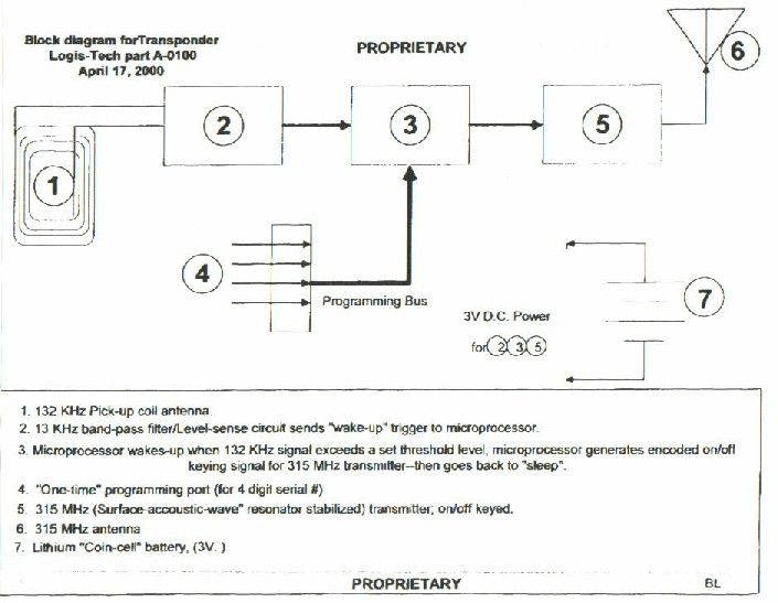
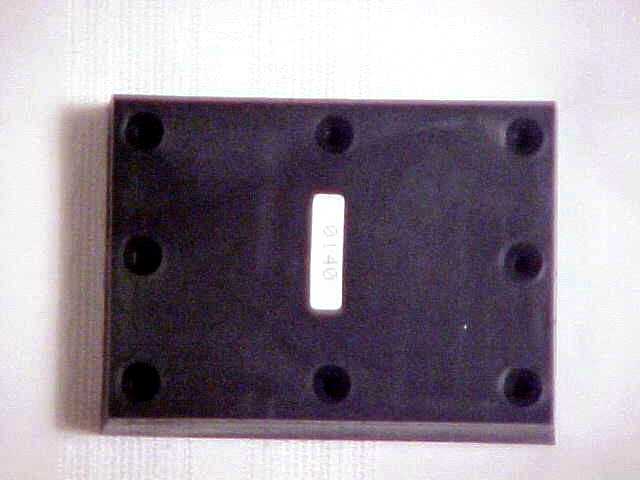
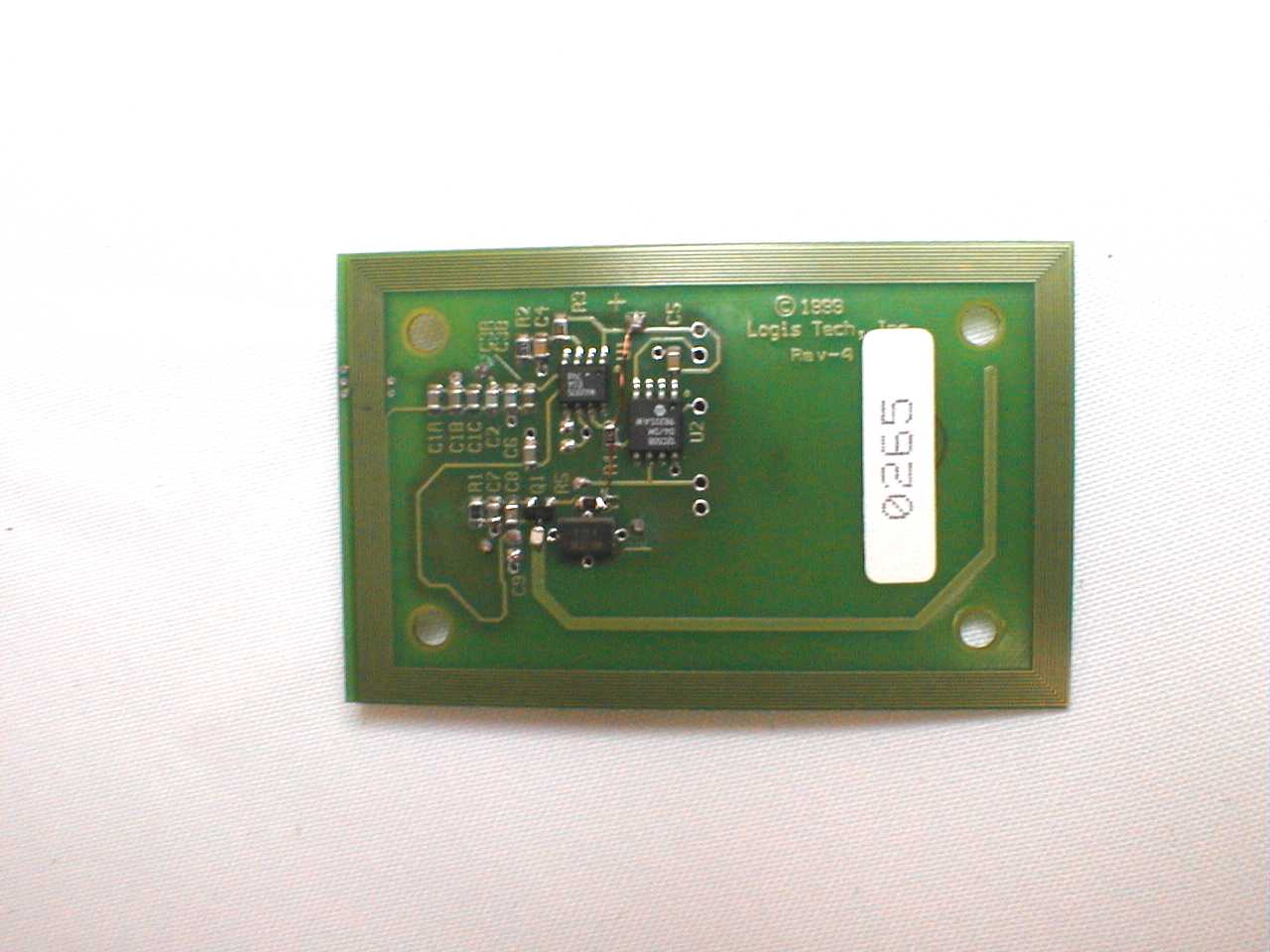
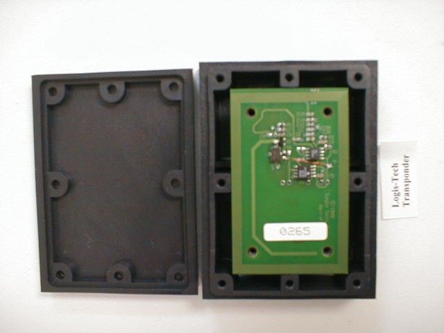
PROPRIETARY PROPRIETARY Automated Inventory and Maintenance Management System (AIMMS) User Manual Logis-Tech, Inc. 5775 Barclay Drive, Suite 4 Alexandria, VA 22315 January 12, 2000 L T ogis ech PROPRIETARY PROPRIETARY 2 The AIMM system is a Radio Frequency Identification system that provides the customer with the ability to manage inventory control and maintenance management without manual intervention. The system operates using low frequency (LF) and Ultra-high frequency (UHF) to “talk” with the various components of the system. Assets to be tracked are identified and a transponder (Tag) is placed on the asset (whether a truck, armored vehicle, or other object). The tags contain a unique identification code that is linked in the database as a specific type of asset belonging to a unit, and assigned such items as an admin number, model number, etc. This data is normally extracted from the Unit Level Logistics System-Ground (ULLS-G) system or other application that is already operating at the activity. The assets are tagged using the adhesive and the Type II nylon pad to the top area of the asset. This is to allow the greatest opportunity for the antennas to “read” the tag as the asset exits or enters the shelters. When the tag is read (interrogated by the LF signal from the portal antenna), it sends the unique ID code contained in the transponder. A receiving antenna embedded in the center of the Portal antenna receives this code. The code is then transmitted to the transceiver unit, which controls the antenna. Once the signal has been Received and processed for validity as an acceptable value, it is transmitted over a LON network to the server, normally located at the ULLS operators or site managers’ area. The server processes the information received over the network, and displays the data in a graphical user interface using web-based technology. The primary components of the AIMM system are shown below. PROPRIETARY PROPRIETARY 3 Transponder: (Tag) Used to tag assets that are to be tracked. The tag will be placed on the top surface of an asset. Placement must consider heavy traffic areas for crew personnel, and clearance for maintenance operations. The ability to open hatches, install equipment and conduct normal operations must not be inhibited. The tags must be placed in areas that cannot be shielded by metal surfaces from the antenna interrogation. See exhibit 3 for a sample of placement on the M-1 Tank. The transponder is secured into the nylon pad, with the battery down. The cover is secured with anti-tamper screws that can be removed to allow replacement of the battery. The unit is sealed against water intrusion prior to the cover being fastened down. The assembled pad and transponder circuit board are referred to as a tag. The unit has an operational range of +65 C. to –40 C. and a battery life of approximately 1.2 million reads. Under normal operational requirements, this represents 3-5 years of battery life. PROPRIETARY PROPRIETARY 4 The battery can be disposed of locally and does not represent a hazardous material issue. The range of the transponder is approximately 22 feet. Transceiver: The transceiver unit controls the transmit and receive antennas and processes the data collected for input onto the network. The system requires local power 110VAC, and does the conversion to 12 volt internally. The system is well grounded and has internal filtering and a fuse to present damage to the unit against electrical surge. The system provides the interfaces for system components along the bottom of the Electro-Magnetic- Interference (EMI) insulated container. The external connection points allow for the system to be plugged in and connected to the network without opening the container. The connection points are AC Power, a 3- prong plug with polarity ground, and two BNC connectors to allow for antenna interface. The antennas are bi-directional, and transmit and receive over a single connection point. Two channels are provided for controlling two antennas allowing for multiple access point monitoring by a single unit. There is also a Light Emitting Diode to provide operator identification of AC power presence, and a RJ-45 (standard network connector) connection point for the network connection. The network connection can be daisy-chained for multiple devices on a network. PROPRIETARY PROPRIETARY 5 Portal Antenna: The portal is a single layer antenna that has embedded a transmit and a receive antenna. The antenna is connected to the transceiver unit, which control the process. The connection is on the reverse side of the antenna, and is a BNC connector fitting. The antenna control circuitry is contained in the small sealed unit under the connection point. The antenna dimensions are 38 “ X 10 “, and have insulated connection points for attachment brackets. The antenna has a solder-mask coating, and is ready for installation in all areas, including outside. The antenna can be painted but does not require any additional preparation. PROPRIETARY PROPRIETARY 6 AGENCY NOTICE Changes or modifications not expressly approved by the manufacturer could void the user’s authority to operate the equipment. PROPRIETARY PROPRIETARY 7 Server and database Cloud Transceiver Maint. Facility/ Offices Network cable toshelters Portal Antenna Transponder Armored vehicles or other assets Exhibit 1 Transceiver Transceiver Transceiver Transponder Armored vehicles or other assets PortalAntenna Transceivers control portal antennas on each access point. They can control two antenna if distaces are between antennas are minimal. PROPRIETARY PROPRIETARY 8 Channel A Channel B Network AC Pow er Power Exhibit 2 BNC Connectors for antenna AC Power LED AC Power Connector RJ-45 Network Connector AIMMS Transceiver Unit, front (Connector side) view PROPRIETARY PROPRIETARY 9
Test Report
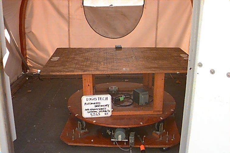
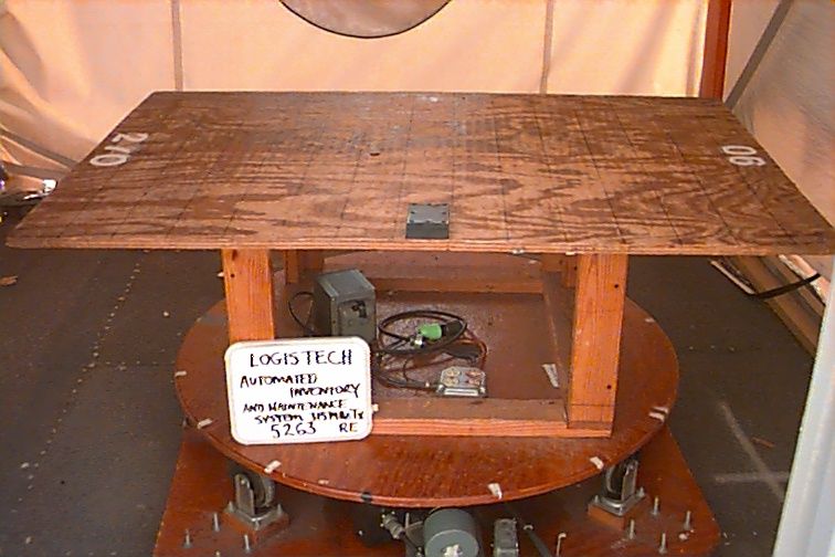
FCC CERTIFICATION TEST REPORT for Logis-Tech, Inc. 5775 Barclay Drive Suite 4 Alexandria, VA 22315 FCC ID: OVU-LTI-A-0100 10 May 2000 WLL PROJECT #: 5263X This report may not be reproduced, except in full, without the prior written consent of Washington Laboratories, Ltd. Logis-Tech, Inc. FCC ID: OVU-LTI-A-0100 WLL Project No.: 5263X i TABLE OF CONTENTS STATEMENT OF QUALIFICATIONS 1.0INTRODUCTION............................................................................................................................................. 1 1.1S UMMARY ........................................................................................................................................................ 1 2.0DESCRIPTION OF EQUIPMENT UNDER TEST (EUT)............................................................................ 1 2.1O N - BOARD O SCILLATO RS ................................................................................................................................1 3.0TEST CONFIGURATION...............................................................................................................................2 3.1T ESTIN G A LGO RITHM ....................................................................................................................................... 2 3.2C ONDUCTED E MISSIONS T ESTIN G .................................................................................................................... 2 3.3R ADIATED E MISSIONS T ESTIN G ........................................................................................................................ 2 3.3.1Radiated Data Reduction and Reporting .............................................................................................. 2 TABLES Table 1.FCC 15.231 3M Radiated Emissions Results Table 2.System Under Test Table 3.Interface Cables Used Table 4.Measurement Equipment Used EXHIBITS Exhibit A.Carrier Bandw idth Data APPENDICES Appendix A.Statement of Measurement Uncertainty Logis-Tech, Inc. FCC ID: OVU-LTI-A-0100 WLL Project No.: 5263X 1 FCC CERTIFICATION TEST REPORT for FCC ID: OVU-LTI-A-0100 1.0Introduction This report has been prepared on behalf of Company to support the attached Application for Equipment Authorization. The test and application are submitted for a Periodic Intentional Radiator under Part 15.231 of the FCC Rules and Regulations. The Equipment Under Test was the Logis-Tech, Inc. 315 MHz Low Power Transmitter used in an Automated Inventory Maintenance Management System. All measurements herein were performed according to the 1992 version of ANSI C63.4. The measurement equipment conforms to ANSI C63.2 Specifications for Electromagnetic Noise and field Strength Instrumentation. Calibration checks are made periodically to verify proper performance of the measuring instrumentation. All measurements are performed at Washington Laboratories, Ltd. test center in Gaithersburg, MD. Site description and site attenuation data have been placed on file with the FCC's Sampling and Measurements Branch at the FCC laboratory in Columbia, MD. Washington Laboratories, Ltd. has been accepted by the FCC and approved by NIST NVLAP (NVLAP Lab Code: 200066-0) as an independent FCC test laboratory. All results reported herein relate only to the equipment tested. The measurement uncertainty of the data contained herein is ± 2.3 dB. Refer to Appendix A for Statement of Measurement Uncertainty. This report shall not be used to claim product endorsement by NVLAP or any agency of the US Government. 1.1Summary The Logis-Tech, Inc, 315 MHz Low Power Transmitter, part of an Automated Inventory Maintenance Management System, complies with the limits for a Periodic Intentional Radiator under Part 15.231 of the FCC Rules and Regulations. 2.0Description of Equipment Under Test (EUT) The Logis-Tech, Inc. Transponder (EUT) is a 315 MHz transmitter unit that is part of a system used for tracking assets in a controlled area. The overall system is the Automated Inventory and Maintenance Management System (AIMMS). The system consists of a transceiver (separate certification, FCC ID: OVU-LTI-A-0101) which transmits a 132 kHz to a portal antenna which is used to activate the 315 MHz Transponder. The Transponder is located on the vehicle as the vehicle passes through the doorway. The vehicle Transponder then transmits a fixed length code that is received by the portal antenna and receiver (separate receiver DOC). This received signal then turns on an indicator light and changes a status from “out” to “in” which stops a timer from counting. The EUT operates from a 3V Lithium battery. 2.1On-board Oscillators The Logis-Tech, Inc. 315 MHz Transponder contains the following oscillators: 315 MHz SAW oscillator. Logis-Tech, Inc. FCC ID: OVU-LTI-A-0100 WLL Project No.: 5263X 2 3.0Test Configuration To complete the test configuration required by the FCC, the transmitter was tested in all three orthogonal planes. 3.1Testing Algorithm The transmitter was turned on and constantly transmitting. The system was tested in all three orthogonal planes. Worst case emissions are recorded in the data tables. 3.2Conducte d Emissions Te sting No conducted emissions testing was performed as the EUT is battery powered. 3.3Radiated Emissions Testing The EUT was placed on an 80 cm high 1 x 1.5 meters non-conductive motorized turntable for radiated testing on a 3 meter open field test site. The emissions from the EUT w ere measured continuously at every azimuth by rotating the turntable. Broadband antennas were mounted on an antenna mast to determine the height of maximum emissions. The height of the antenna was varied between 1 and 4 meters. Both the horizontal and vertical field components were measured. The output from the antenna was connected, via a preamplifier, to the input of the spectrum analyzer. The detector function was set to quasi-peak or peak, as appropriate. The measurement bandwidth on the spectrum analyzer system was set to at le…
Text truncated - open the document above for the full version.
Contact Information
Applicant
James K. Bounds(VP & General Counsel)
703-921-1038Fax: 703-921-1260
Technical Contact
Washington Laboratories, Ltd.Gregory Snyder
[email protected](301) 417-0220
7560 Lindbergh Drive · Gaithersburg · United States
Non-Technical Contact
Washington Laboratories, Ltd.Brian Dettling
[email protected](301) 417-0220
Test Firm
Washington Laboratories, Ltd.Michael Violette
Technical Specifications
| # | Rule Parts | Frequency Range | Power Output |
|---|---|---|---|
| 1 | 15C | 315 MHz - 315 MHz | - |
Other Applications from Logis-Tech, Inc.

OVU-LTI-A-0101
Apr 18, 2000TD System TX
Equipment Class
DCD - Part 15 Low Power Transmitter Below 1705 kHz