OW3BT101
Microsoft Corporation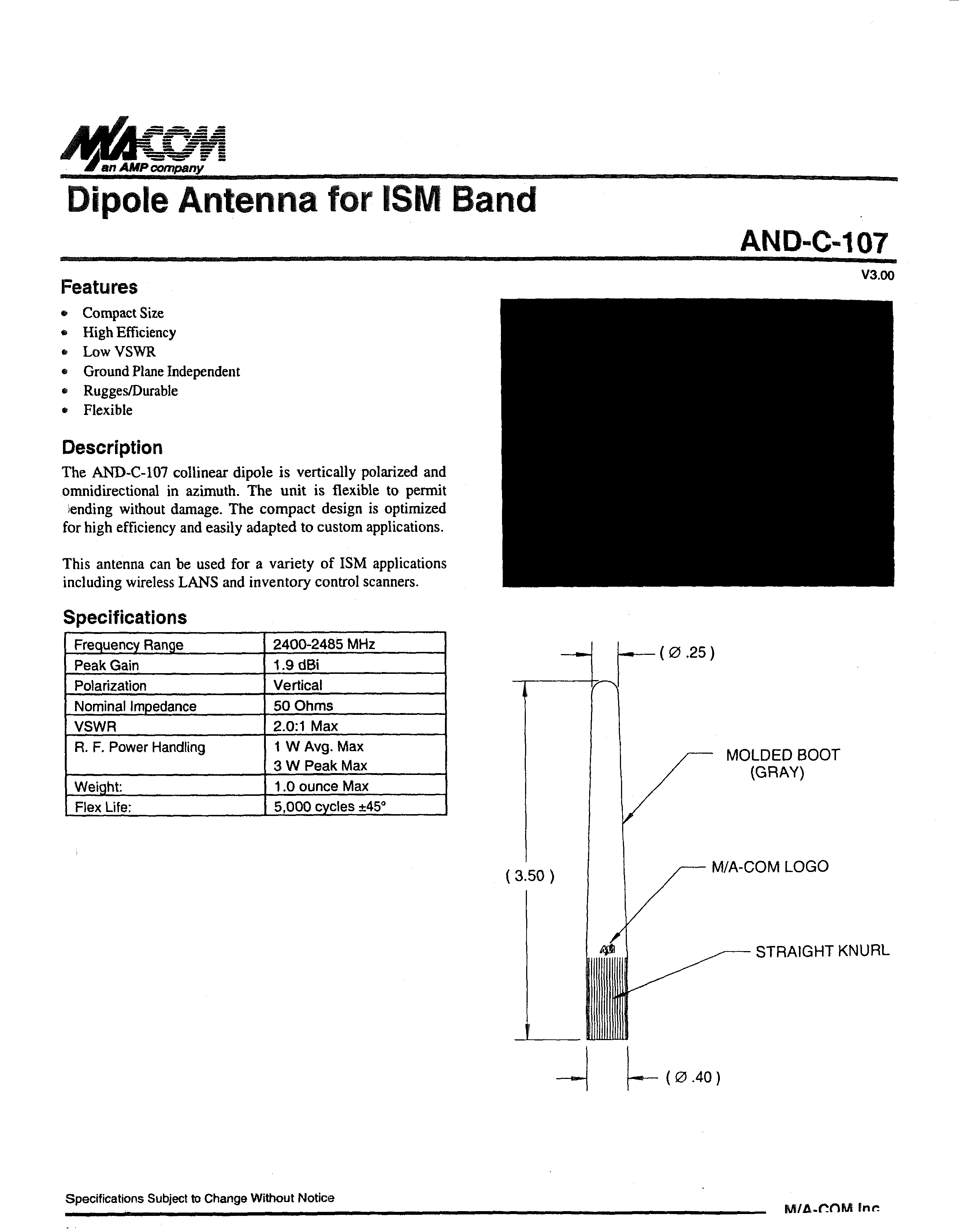
Click to zoom
Application Details
- Equipment Class
- DSS - Part 15 Spread Spectrum Transmitter
- Date of Grant
- Apr 19, 2001
- Application Purpose
- Original Equipment
- Date of Application
- Sep 11, 2000
- Frequency Range
- 2402.00000000 - 2480.00000000
- Company
- Microsoft Corporation
- Country
- United States
Documents & Files
Document Text
Text extracted from the exhibit documents filed with the FCC. Open a document above to read the original.
Users Manual
CONFIDENTIAL 26 July 2000 Exhibit 10FCC ID: OW3BT101 Applicant: Nokia Mobile PhonesCopyright © 2000 Nokia Mobile Phones MANUALS (STATEMENT FOR LRB-1) The LRB-1 module will be installed professionally in customer products. The provided functions will be described in the manuals of the customer products.
Users Manual
CONFIDENTIAL 02 November 2000 Exhibit 10 revision 0.1FCC ID: OW3BT101 Applicant: Nokia Mobile PhonesCopyright © 2000 Nokia Mobile Phones 1/11 INFORMATION - MANUAL LRB-1 IS A BLUETOOTH TRANSCEIVER COMPONENT AND WILL ONLY BE USED BY NOKIA IN APPROPRIATE PRODUCTS. THESE PRODUCTS WILL HAVE TO BE TESTED AGAIN FOR COMPLIANCE. WARNING: USERS ANS INSTALLERS MUST USE ONLY THOSE ANTENNAS SPECIFIED BY NOKIA, TO COMPLY WITH FCC'S R.F. EXPOSURE REQUIREMENTS TO AVOID EPOSING PERSONS TO HARMFUL R.F. RADIATION. DO NOT SUBSTITUTE ANY SUPPLIED ANTENNA RECOMMENDED BY THE SUPPLIER. CONTACT YOUR SUPPLIER FOR FURTHER INSTRUCTIONS. LRB-1 Nokia Bluetooth Tranceiver Component - Preliminary Information - Nov 2000 Confidential 2/11 LRB-1 Nokia Bluetooth Transceiver Component Product Features q Complete stand-alone Class 2 Bluetooth transceiver system q Including baseband controller, 2.45 GHz radio part and firmware up to HCI q Bluetooth V 1.0 B compliant and pre-certified q Suitable for both voice and data applications q Point-to-Multipoint connection support q Park, Hold and Sniff modes q High speed UART and flexible PCM data interfaces q Several programmable control interfaces plus ADC input q Internal oscillators and power regulators q Adjustable I/O voltages q completely shielded and FCC approved q Optimized size and form-factor: 23 x 19 x 2 mm 3 WARNING : LRB-1 IS A BLUETOOTH TRANSCEIVER COMPONENT, WHICH HAVE BEEN TESTED WITH A RECOMMENDED ANTENNA DESIGN AND SHOULD ONLY BE USED BY NOKIA IN APPROPRIATE PRODUCTS. THESE PRODUCTS WILL HAVE TO BE TESTED AGAIN FOR COMPLIANCE. USERS ANS INSTALLERS MUST USE ONLY THOSE ANTENNAS SPECIFIED BY NOKIA, TO COMPLY WITH FCC'S R.F. EXPOSURE REQUIREMENTS TO AVOID EPOSING PERSONS TO HARMFUL R.F. RADIATION. DO NOT SUBSTITUTE ANY SUPPLIED ANTENNA RECOMMENDED BY THE SUPPLIER. CONTACT YOUR SUPPLIER FOR FURTHER INSTRUCTIONS. LRB-1 Nokia Bluetooth Tranceiver Component - Preliminary Information - Nov 2000 Confidential 3/11 Overview The LRB-1 Nokia Bluetooth Tranceiver Component is a highly integrated multi-chip component which represents a complete standalone Bluetooth transceiver system for short-range wireless applications. All necessary components including the baseband controller, the radio part for the 2.45 GHz system and a flash memory of 2 MBit are integrated on a single PCB using advanced flip chip interconnection techniques. The Bluetooth Tranceiver Component is delivered with all needed firmware of the Bluetooth protocol stack up to HCI which resides in the on-board flash memory. A traditional high-IF radio architecture providing good sensitivity has been used. LRB-1 Nokia Bluetooth Tranceiver Component - Preliminary Information - Nov 2000 Confidential 4/11 Block Diagram 2.4GHzSAW 111MHzBALUNDEMOD-TANK 13MHz RESETX SLEEPX OSCON OSCON 32kHz TCK OSCON TRST OSCONTDI OSCON TDO OSCONTMS OSCON WRX OSCON CSXWRXRDX JTAG 5 DATA 16 ADDR 17 DBUSRF 3 RFDATA 2 BBCLK VPP OSCON 12 GPP CENX GPP0 GPP1 GPP2 GPP3 GPP4 GPP5 GPP6 GPP7 GPP8 GPP9 GPP10 GPP11 ADCIN ADCREF VDD VAPPL BBON VBBEN VCCADC VBB VCC ADCREG VCCVCO GND GND GND GND OSCON Radio Baseband Flash Memory ANT 2 SPDT DBUSRFCLK OSCON DBUSRFDA OSCONDBUSRFENX OSCON RFDATA1 OSCON RFDATA2 OSCON VIO RDY OSCON TXON LRB-1 Nokia Bluetooth Tranceiver Component - Preliminary Information - Nov 2000 Confidential 5/11 Functional Description A. Key Components The LRB-1 Nokia Bluetooth Transceiver Component consists of three integrated circuits plus a couple of smaller active and passive passive components. All three chips are using state-of-the-art semiconductor technologies and are mounted on the MCM substrate using flip-chip techniques: q Baseband ASIC: This chip, running at 1.8 V is a pure CMOS ASIC including the ARM7TDMIE microcontroller core, embedded RAMs and the core logic for MIPS consuming Bluetooth tasks. Due to the fact that only the MIPS consuming tasks are realized in hardware and that a central buffer RAM instead of dedicated connection buffers are used, this approach has been proven to be flexible and future-proof. q Radio ASIC: The radio chip in BiCMOS technology works as the transceiver chip for the ISM band of 2400-2483 MHz which is used for Bluetooth transmission. Implemented on-chip function blocks include the PLL, LNA, mixer and Gaussian modulator as well as 13 MHz crystal oscillator and all neded voltage regulators. q Flash Memory: An industry-standard 16-bit wide 2 MBit Flash memory running at 1.8 V with an access time of 120 ns has been implemented on the LRB-1 module. Sectoring is used to allow also the storage of non- volatile configuration information (e.g. BD address) on the device. LRB-1 Nokia Bluetooth Tranceiver Component - Preliminary Information - Nov 2000 Confidential 6/11 B. Hardware Interfaces for Data Two different hardware interfaces for link data are supported: A high-speed UART interface for data applications and a 4-wire PCM interface for audio data. The main features of the interface imple- mentations are as follows: q UART Interface: A full-duplex UART has been implemented on the LRB-1 module with programmable stopbit length and parity check which supports a wide range of industry-standard baud rates up to 921.6 kBaud using 7-times oversampling: Baud Rate [bit/s]Baud Rate [bit/s]Baud Rate [bit/s] 720038400230400 960057600307200 1440076800460800 19200115200921600 28800153600 q PCM Interface: A standard 4-wire PCM interface with 8 kHz sample rate has been imple…
Text truncated - open the document above for the full version.
Users Manual
CONFIDENTIAL 18 April 2001 Exhibit 10 FCC ID: OW3BT101 Rev. 0.2 Applicant: Nokia Mobile Phones Copyright © 2001 Nokia Mobile Phones 1/11 INFORMATION - MANUAL LRB-1 IS A BLUETOOTH TRANSCEIVER COMPONENT AND WILL ONLY BE USED BY NOKIA IN APPROPRIATE PRODUCTS. THESE PRODUCTS WILL HAVE TO BE TESTED AGAIN FOR COMPLIANCE. WARNING : USERS ANS INSTALLERS MUST USE ONLY THOSE ANTENNAS SPECIFIED BY NOKIA, TO COMPLY WITH FCC'S R.F. EXPOSURE REQUIREMENTS TO AVOID EPOSING PERSONS TO HARMFUL R.F. RADIATION. DO NOT SUBSTITUTE ANY SUPPLIED ANTENNA RECOMMENDED BY THE SUPPLIER. CONTACT YOUR SUPPLIER FOR FURTHER INSTRUCTIONS. LRB-1 Nokia Bluetooth Tranceiver Component - Preliminary Information - April 2001 Confidential 2/11 LRB-1 Nokia Bluetooth Transceiver Component Product Features q Complete stand-alone Class 2 Bluetooth transceiver system q Including baseband controller, 2.45 GHz radio part and firmware up to HCI q Bluetooth V 1.0 B compliant and pre-certified q Suitable for both voice and data applications q Point-to-Multipoint connection support q Park, Hold and Sniff modes q High speed UART and flexible PCM data interfaces q Several programmable control interfaces plus ADC input q Internal oscillators and power regulators q Adjustable I/O voltages q completely shielded and FCC approved q Optimized size and form-factor: 23 x 19 x 2 mm 3 WARNING : LRB-1 IS A BLUETOOTH TRANSCEIVER COMPONENT, WHICH HAVE BEEN TESTED WITH A RECOMMENDED ANTENNA DESIGN AND SHOULD ONLY BE USED BY NOKIA IN APPROPRIATE PRODUCTS. THESE PRODUCTS WILL HAVE TO BE TESTED AGAIN FOR COMPLIANCE. USERS ANS INSTALLERS MUST USE ONLY THOSE ANTENNAS SPECIFIED BY NOKIA, TO COMPLY WITH FCC'S R.F. EXPOSURE REQUIREMENTS TO AVOID EPOSING PERSONS TO HARMFUL R.F. RADIATION. DO NOT SUBSTITUTE ANY SUPPLIED ANTENNA RECOMMENDED BY THE SUPPLIER. CONTACT YOUR SUPPLIER FOR FURTHER INSTRUCTIONS. LRB-1 Nokia Bluetooth Tranceiver Component - Preliminary Information - April 2001 Confidential 3/11 Overview The LRB-1 Nokia Bluetooth Tranceiver Component is a highly integrated multi-chip component which represents a complete standalone Bluetooth transceiver system for short-range wireless applications. All necessary components including the baseband controller, the radio part for the 2.45 GHz system and a flash memory of 2 MBit are integrated on a single PCB using advanced flip chip interconnection techniques. The Bluetooth Tranceiver Component is delivered with all needed firmware of the Bluetooth protocol stack up to HCI which resides in the on-board flash memory. A traditional high-IF radio architecture providing good sensitivity has been used. COMPLIANCE STATEMENT The compliance statement has to be placed in the manuals of the host device. This device contains FCC Id : OW3BT101 MARKING OF THE FINAL DEVICE The following label has to be placed on the final device : THIS DEVICE COMPLIES WITH PART 15 OF THE FCC RULES: OPERATION IS SUBJECT TO THE CONDITION THAT THIS DEVICE DOES NOT CAUSE HARMFUL INTERFERENCE, AND THIS DEVICE MUST ACCEPT ANY INTERFERENCE RECEIVED, INCLUDING INTERFERENCE THAT MAY CAUSE UNDESIRED OPERATION. FCC ID : OW3BT101 Model : BT101 CANADA : 661391179A Serial No : On module lid This device contains FCC Id: OW3BT101 LRB-1 Nokia Bluetooth Tranceiver Component - Preliminary Information - April 2001 Confidential 4/11 Block Diagram 2.4GHz SAW 111MHz BALUN DEMOD-TANK 13MHz RESETX SLEEPX OSCON OSCON 32kHz TCK OSCONTRST OSCONTDI OSCONTDO OSCONTMS OSCONWRX OSCON CSX WRX RDX JTAG 5 DATA 16 ADDR 17 DBUSRF 3 RFDATA 2 BBCLK VPP OSCON 12 GPP CENX GPP0 GPP1 GPP2 GPP3 GPP4 GPP5 GPP6 GPP7 GPP8 GPP9 GPP10 GPP11 ADCIN ADCREF VDD VAPPL BBON VBBEN VCCADC VBB VCC ADCREG VCCVCO GND GND GND GND OSCON Radio Baseband Flash Memory ANT 2 SPDT DBUSRFCLK OSCON DBUSRFDA OSCONDBUSRFENX OSCON RFDATA1 OSCONRFDATA2 OSCON VIO RDY OSCON TXON LRB-1 Nokia Bluetooth Tranceiver Component - Preliminary Information - April 2001 Confidential 5/11 Functional Description A. Key Components The LRB-1 Nokia Bluetooth Transceiver Component consists of three integrated circuits plus a couple of smaller active and passive passive components. All three chips are using state-of-the-art semiconductor technologies and are mounted on the MCM substrate using flip-chip techniques: q Baseband ASIC: This chip, running at 1.8 V is a pure CMOS ASIC including the ARM7TDMIE microcontroller core, embedded RAMs and the core logic for MIPS consuming Bluetooth tasks. Due to the fact that only the MIPS consuming tasks are realized in hardware and that a central buffer RAM instead of dedicated connection buffers are used, this approach has been proven to be flexible and future-proof. q Radio ASIC: The radio chip in BiCMOS technology works as the transceiver chip for the ISM band of 2400-2483 MHz which is used for Bluetooth transmission. Implemented on-chip function blocks include the PLL, LNA, mixer and Gaussian modulator as well as 13 MHz crystal oscillator and all neded voltage regulators. q Flash Memory: An industry-standard 16-bit wide 2 MBit Flash memory running at 1.8 V with an access time of 120 ns has been implemented on the LRB-1 module. Sectoring is used to allow also the storage of non- volatile configuration information (e.g. BD address) on the device. LRB-1 Nokia Bluetooth Tranceiver Component - Preliminary Information - April 2001 Confidential 6/11 B. Hardware Interfaces for Data Two different hardware interfaces for link data are supported: A high-s…
Text truncated - open the document above for the full version.
Cover Letter(s)
CONFIDENTIAL 02 November 2000 Answer to EA98731FCC ID: OW3BT101 Applicant: Nokia Mobile PhonesCopyright © 2000 Nokia Mobile Phones Answers to Information request EA98731 of FCC from 21 st of Sep. 2000 Question 1. All tests have been performed with two different antennas, a 0 dBi integral antenna and a 1.9 dBi antenna. The Bluetooth Tranceiver Component LRB-1 provides a unique antenna port, which can be used with different antennas. Nokia recomments a 0dBi antenna. The tests with the 1.9 dBi antenna were conducted for information only. The Bluetooth Tranceiver Component is designed according Bluetooth specification as Power Class II Component. Class II Components have to stay within the limts of –6 dBm and +4 dBm. LRB-1 is a 1 mW (Uncertainty +/- 0.5 mW) Bluetooth Tranceiver Component. The test sample had a measured peak conducted power of 1.26 mW, which is right in our specification. With this document corrected documents will be provided. Question 2. LRB-1 is a Bluetooth Transceiver Component and will only be used by Nokia in appropriate products. These products will have to be tested again for compliance. Question 3. The MPE test was conducted for information only. Depending on the product that the Bluetooth Tranceiver Component is used with, the final device could be subject to routine evaluation for RF exposure, either SAR limits or MPE limits. CONFIDENTIAL 02 November 2000 Answer to EA98731FCC ID: OW3BT101 Applicant: Nokia Mobile PhonesCopyright © 2000 Nokia Mobile Phones Question 4. LRB-1 is a Bluetooth Transceiver Component and will only be used by Nokia in appropriate products.These products will have to be tested again for compliance. The Bluetooth Transceiver Component covers the following functionalitity according FCC Public Notice DA 00-1407 (Part 15 Unlicensed Modular Transmitter Approval) : 1.The Bluetooth Transceiver Component has its own RF shielding. Details of the shielding can be found in Exhibit 02 (Marking of Lid)and Exhibit 03 (Position of Lid) 2.The Bluetooth Transceiver Component contains a flash memory, which buffers modulation and data inputs. Details can be found in Exhibit 11 (Block Diagram) 3.LRB-1 has it's own power supply. The input voltage range is 2.95 V – 5.2 V DC.Details can be found in Exhibit 12 (Schematic Diagrams). 4.LRB-1 provides a unique antenna connection at connection pin 14. Nokia recommends an antenna design. Details can be found in Exhibit 01 revision 0.1 (Information Manual), which will be provided with this document. This antenna has been used for the tests. LRB-1 will only be used by Nokia in appropriate products, which could have a unique antenna. These products will have to be tested again for compliance. 5.LRB-1 was tested in a stand-alone configuration. The Bluetooth Transceiver Component was assembeled on a Development board to provide LRB-1 with commands. The devlopment board contains an antenna according the Nokia Antenna recommendation. 6.The Bluetooth Transceiver Componentis labeled with it's own FCC ID number. Details of the labeling can be found in Exhibit 02 (Marking of Lid)and Exhibit 03 (Position of Lid). LRB-1 will only be used by Nokia in appropriate products. These products will either have an exterior label referring CONFIDENTIAL 02 November 2000 Answer to EA98731FCC ID: OW3BT101 Applicant: Nokia Mobile PhonesCopyright © 2000 Nokia Mobile Phones To the enclosed module or have to be tested again for compliance. 7.LRB-1 will only be used by Nokia in appropriate products. Details can be found in Exhibit 01 revision 0.1 (Information Manual), which will be provided with this document. 8.The maximum RF power output from the LRB-1 Bluetooth Tranceiver Component is 0 dBm or about 1 milliwatt. The Bluetooth Tranceiver Component is designed to use a simple antenna with a nominal gain of 0 dBi as the radiating element. The SAR limit would not be exceeded, even if the entire RF power output were absorbed by 1 gram of tissue, which is not possible with a typical RF circuit. With a seperating distance of 20 cm the MPE limits are well above the potential a 1 milliwatt device is capable of producing. This has been shown by measurement results according to standard MPE tests, which are still on noise level for an active LRB-1 Bluetooth Tranceiver Component. The MPE test was conducted for information only, since at an EIRP of 0,813 mW max. for the tested Bluetooth Tranceiver Component. Depending on the product that the Bluetooth Tranceiver Component is used with, the final device could be subject to routine evaluation for RF exposure, either SAR limits or MPE limits. CONFIDENTIAL 02 November 2000 Answer to EA98731FCC ID: OW3BT101 Applicant: Nokia Mobile PhonesCopyright © 2000 Nokia Mobile Phones Question 5. and 6. Photos will be provided with this document. Question 7. LRB-1 is a Bluetooth Transceiver Component and will only be used by Nokia in appropriate products. These products will have to be tested again for compliance. The information document will be provide as Exhibit 10 revision 0.1 (Information Manual) with this document.
Cover Letter(s)
CONFIDENTIAL 6 th March 2001 Answer to EA98731FCC ID: OW3BT101 Reference Document 17744 Applicant: Nokia Mobile PhonesCopyright © 2001 Nokia Mobile Phones Response to Information request EA98731, documents reference number 17744 of FCC from 18 th of January 2001. Information with regard to the Bluetooth device operates under the Frequency Hopping Spread Spectrum (FHSS) requirements. Question 1. Minimum channel separation requirement The channel spacing of the device is 1 MHz. Following plots of a spectrum analyzer show the separation between peaks and adjacent channels in 79 channel mode. A UnitdBm RF Att 20 dB Ref Lvl 10 dBm Ref Lvl 10 dBm Center2.442 GHzSpan100 MHz10 MHz/ 2MAX2MA RBW 200 kHz VBW 10 kHz SWT 125 ms -90 -80 -70 -60 -50 -40 -30 -20 -10 0 10 11 Delta 1 [T2] 0.00 dB 0.00000000 Hz Date: 22.FEB.2001 08:57:41 Figure 1- Complete Sequence: This figure shows the full hopping channel sequence. 79 channels with 1MHz channel separation can be seen. CONFIDENTIAL 6 th March 2001 Answer to EA98731FCC ID: OW3BT101 Reference Document 17744 Applicant: Nokia Mobile PhonesCopyright © 2001 Nokia Mobile Phones A UnitdBm RF Att 20 dB Ref Lvl 10 dBm Ref Lvl 10 dBm Center2.45 GHzSpan10 MHz1 MHz/ RBW 200 kHz VBW 10 kHz SWT 12.5 ms 2MA2MAX -90 -80 -70 -60 -50 -40 -30 -20 -10 0 10 11 Marker 1 [T2] 0.03 dBm 2.45107214 GHz 1 [T2] 0.03 dBm 2.45107214 GHz 1 [T2] -0.00 dB -1.00200401 MHz Date: 22.FEB.2001 08:54:24 Figure 2 -Channel Spacing: This sweep was made over a span of 10 MHz to show more detail. Here from the 1 MHz channel spacing can be derived. CONFIDENTIAL 6 th March 2001 Answer to EA98731FCC ID: OW3BT101 Reference Document 17744 Applicant: Nokia Mobile PhonesCopyright © 2001 Nokia Mobile Phones Question 2. Pseudorandom hop sequence The pseudorandom sequence is generated in a nine-stage shift register whose 5 th and 9 th stage outputs are added in a module-two addition stage with the result fed back to input of the first stage. The following are two examples of possible 79 hopping sequences with channels identified as 0 through 78. The channel numbering scheme starts with channel 0 at 2402 MHz with the 79 th channel then appearing at 2480 MHz as channel 78. Sequence example a: 01, 51, 03, 55, 05, 04, 07, 08, 72, 57, 74, 61, 76, 10, 78, 14, 09, 59, 11, 63, 13, 12, 15, 16, 17, 65, 19, 69, 21, 18, 23, 22, 33, 67, 35, 71, 37, 20, 39, 24, 25, 73, 27, 77, 29, 26, 31, 30, 41, 75, 43, 00, 45, 28, 47, 32, 17, 02, 21, 04, 19, 34, 23, 36, 33, 06, 37, 08, 35, 38, 39, 40, 25, 10, 29, 12, 27, 42, 31 Sequence example b: 55, 26, 19, 20, 23, 22, 53, 40, 57, 42, 21, 36, 25, 38, 27, 63, 31, 65, 74, 59, 78, 61, 29, 00, 33, 02, 76, 75, 01, 77, 35, 71, 39, 73, 03, 67, 07, 69, 37, 08, 41, 10, 05, 04, 09, 06, 43, 16, 47, 18, 11, 12, 15, 14, 45, 32, 02, 66, 47, 60, 49, 64, 04, 54, 06, 58, 51, 52, 53, 56, 08, 70, 10, 74, 55, 68, 57, 72, 59 CONFIDENTIAL 6 th March 2001 Answer to EA98731FCC ID: OW3BT101 Reference Document 17744 Applicant: Nokia Mobile PhonesCopyright © 2001 Nokia Mobile Phones Question 3. Use of each frequency equally on average Every Bluetooth unit has an internal system clock that determines the timing and hopping of the transceiver. The Bluetooth clock is derived from a free running native clock, which is never adjusted and is never turned off. For synchronization with other units, only offsets are used that, added to the native clock, provide temporary Bluetooth clocks which are mutually synchronized. The Bluetooth master determines the timing and the frequency hopping on the channel of a piconet. The hop selection scheme consists of the selection of a sequence and the mapping of this sequence on the hop frequencies. In the connection state, the clock bits to use in the hopping sequence generation are always according to the master clock. A sending unit transmits the FHS (frequency hopping selection) packet. It contains UAP (upper address part) / LAP (lower address part) as well as clock information which is updated before retransmission in the inquiry state. The output from the selection box constitutes a pseudorandom sequence covering 79 hops. Question 4. Receiver matching bandwidth and synchronization Receiver bandwidth The receiver bandwidth in the 79 channel hopping mode is 1 MHz. Synchronization Synchronization within a piconet uses a system of beacon channels generated by the master unit with the remaining slave units periodically waking up and listening on a beacon channel. Beacon channels are designated by the master unit in page mode to identify channels for slave units to listen to. The beacon channel packet also contains the synchronization information required for the slave to synchronize with the master unit. If the two Bluetooth devices have exchanged information during the last five hours, the typical time it takes to establish the connection is reduced considerably due to the ability of the paging unit to estimate at what frequency the other unit will perform the page scan. Question 5. Minimum number of channels The Bluetooth device uses 79 channels in US/Europe hopping sequence mode. CONFIDENTIAL 6 th March 2001 Answer to EA98731FCC ID: OW3BT101 Reference Document 17744 Applicant: Nokia Mobile PhonesCopyright © 2001 Nokia Mobile Phones Question 6. 10 dB bandwidth plots The occupied bandwidth of the device, which has to be below 1 MHz following the 20 dB bandwidth requirement, can be found on page 39, 40 and 41 of the test report. Figures 3 to 5 show plots of the 10 dB bandwidth for lower, mid and upper channel. A UnitdBm RFAtt20dB RefLvl 10dBm RefLvl 10dBm RBW10kHz SWT50ms VBW10kHz Center2.402GHzSpan2MHz200kHz/ 1VIEW1MA -90 -80 -70 -60 -50 -40 -30 -20 -10 0 10 1 1 2 Marker1[T1] -5.62dBm 2.40198196GHz 1[T1]-5.62dBm 2.40198196GHz 1[T1]-12.02dB -216.43286573kHz 2[T1]-10.05dB 264.52905812kHz Date:6.MAR.200108:22:37 Figure 3-10 dB Bandwidth: Plot 10 dB bandwidth for lower channel: 481 MHz CONFIDENTIAL 6 th March 2001 Answer to EA98731FCC ID: OW3BT101 Reference Document 17744 Applicant: No…
Text truncated - open the document above for the full version.
Cover Letter(s)
CONFIDENTIAL 18 April 2001 Answer to EA98731 FCC ID: OW3BT101 Reference Document 18893 Applicant: Nokia Mobile Phones Copyright © 2001 Nokia Mobile Phones Response to information request EA98731, document reference number 18893 of FCC from 17 th April 2001. Question 1. Confidential documents The photos and the processing gain document can be public. An updated document with the list of confidential documents will be submitted with this response. New document reference : Confidential Documents List Exhibit20_rev01_Confid.pdf Question 2. Labeling and Compliance statement Due to the size of the component, the device can't be labeled. The FCC Identifier will be lasered on the component. The compliance statement will be delivered with the host device. The label document and the compliance statement have been updated. A second label will be provided on the host device to reference the LRB-1 component. The updated documents will be submitted with this response. New document reference : Label Exhibit02_rev01_Label.pdf Label Location Exhibit03_rev01_Lable_location.pdf Compliance Statement Exhibit04_rev01_Compliance_statement.pdf Manual Information Exhibit10_rev02_Manual.pdf Question 3. Grant condition The grant condition can be accepted.
Cover Letter(s)
Exhibit 20 FCC ID: OW3BT101 Rev. 01 Applicant: Nokia Mobile Phones Copyright © 2001 Nokia Mobile Phones NOKIA MOBILE PHONES Meesmannstr. 103 D-44807 Bochum GERMANY Tel. +49 234 984 0 Fax. +49 234 984 3070 April 18th, 2001 Federal Communications Commission, Authorization & Evaluation Division, 7435 Oakland Mills Road, Columbia, MD. 21046 Attention: Equipment Authorization Branch REQUEST FOR CONFIDENTIALITY Pursuant to Sections 0.457 (d) (l) (ii) and 0.459 of the Commission’s Rules, the Applicant hereby requests confidential treatment of some of the information accompanying this Application of FCC ID: OW3BT101 and as outlined below: - Exhibit 11 : Block Diagram - Exhibit 12 : Schematic Diagrams - Exhibit 13 : Theory of Operation - Exhibit 16 : List of Active Devices - Exhibit 17 : Description of Alignment Procedures These materials contain trade secrets and proprietary information not customarily released to the public and the public disclosure of these matters might be harmful to the Applicant and provide unjustified benefits to its competitors. Exhibit 20 FCC ID: OW3BT101 Rev. 01 Applicant: Nokia Mobile Phones Copyright © 2001 Nokia Mobile Phones The Applicant understands that pursuant to Rule 0.457 (d) (l) (ii) disclosure of this Application and all accompanying documentation will not be made before the date of the Grant for this Application. NOKIA MOBILE PHONES Guido Paland Test Engineer, R&D Center, Bochum Germany
External Photos
Specifications Subject to Change Without Notice M/A-COM Inc. North America: Tel. (800) 366-2266 iAsia/Pacific: Tel. +85 2 2111 8088iEurope:Tel. +44 (1344) 869-595 Fax (800) 618-8883Fax +85 2 2111 8087Fax +44 (1344) 300-020 Dipole Antenna for ISM Band AND-C-107 V3.00 Features x Compact Size x High Efficiency x Low VSWR x Ground Plane Independent x Rugges/Durable x Flexible Description The AND-C-107 collinear dipole is vertically polarized and omnidirectional in azimuth. The unit is flexible to permit bending without damage. The compact design is optimized for high efficiency and easily adapted to custom applications. This antenna can be used for a variety of ISM applications including wireless LANS and inventory control scanners. Specifications Frequency Range2400-2485 MHz Peak Gain1.9 dBi PolarizationVertical Nominal Impedance50 Ohms VSWR2.0:1 Max R. F. Power Handling1 W Avg. Max 3 W Peak Max Weight:1.0 ounce Max Flex Life:5,000 cycles ±45° STRAIGHT KNURL M/A-COM LOGO MOLDED BOOT (GRAY) ( ∅ .40 ) ( ∅ .25 ) ( 3.50 ) Dipole Antenna for ISM BandAND-C-107 V3.00 Specifications Subject to Change Without Notice M/A-COM Inc. North America: Tel. (800) 366-2266 i Asia/Pacific: Tel. +85 2 2111 8088 i Europe:Tel. +44 (1344) 869-595 Fax (800) 618-8883Fax +85 2 2111 8087Fax +44 (1344) 300-020 Typical Electrical Performance Azimuth 180° Elevation 90° 90° 270° 180° 0° 0° 0° 90° 90°
External Photos
CONFIDENTIAL October 2000 FCC ID: OW3BT101 Applicant: Nokia Mobile PhonesCopyright © 2000 Nokia Mobile Phones PHOTOGRAPHS External antenna Type :M/A-COM, AND-C-107 CONFIDENTIAL October 2000 FCC ID: OW3BT101 Applicant: Nokia Mobile PhonesCopyright © 2000 Nokia Mobile Phones
ID Label/Location Info
CONFIDENTIAL 18 April 2001 Exhibit 3 FCC ID: OW3BT101 Rev. 01 Applicant: Nokia Mobile Phones Copyright © 2001 Nokia Mobile Phones LOCATION OF LABEL 1.) POSITION OF LID ( LOCATION OF LABEL SHOWING FCC ID ) 2. ) MARKING OF THE FINAL DEVICE : The following label has to be placed on the final device : This device contains FCC Id: OW3BT101
ID Label/Location Info
CONFIDENTIAL 18 April 2001 Exhibit 4 FCC ID: OW3BT101 Rev. 01 Applicant: Nokia Mobile Phones Copyright © 2001 Nokia Mobile Phones COMPLIANCE STATEMENT The compliance statement will be placed in the manuals of the final device. THIS DEVICE COMPLIES WITH PART 15 OF THE FCC RULES: OPERATION IS SUBJECT TO THE CONDITION THAT THIS DEVICE DOES NOT CAUSE HARMFUL INTERFERENCE, AND THIS DEVICE MUST ACCEPT ANY INTERFERENCE RECEIVED, INCLUDING INTERFERENCE THAT MAY CAUSE UNDESIRED OPERATION. FCC ID : OW3BT101 Model : BT101 CANADA : 661391179A Serial No : On module lid
Internal Photos
CONFIDENTIAL 26 July 2000 Exhibit 6FCC ID: OW3BT101 Applicant: Nokia Mobile PhonesCopyright © 2000 Nokia Mobile Phones PHOTOGRAPHS BT101 Topside with shielding
Internal Photos
CONFIDENTIAL 26 July 2000 Exhibit 7FCC ID: OW3BT101 Applicant: Nokia Mobile PhonesCopyright © 2000 Nokia Mobile Phones PHOTOGRAPHS BT101 Bottom
Internal Photos
CONFIDENTIAL 26 July 2000 Exhibit 8FCC ID: OW3BT101 Applicant: Nokia Mobile PhonesCopyright © 2000 Nokia Mobile Phones PHOTOGRAPHS BT101 Testboard Bottom
Internal Photos
CONFIDENTIAL 26 July 2000 Exhibit 9FCC ID: OW3BT101 Applicant: Nokia Mobile PhonesCopyright © 2000 Nokia Mobile Phones PHOTOGRAPHS BT101 Testboard Topside
Internal Photos
CONFIDENTIAL October 2000 FCC ID: OW3BT101 Applicant: Nokia Mobile PhonesCopyright © 2000 Nokia Mobile Phones PHOTOGRAPHS On board antenna patch antenna
Operational Description
CONFIDENTIAL 26 July 2000 Exhibit 15FCC ID: OW3BT101 Applicant: Nokia Mobile PhonesCopyright © 2000 Nokia Mobile Phones DESCRIPTION OF CIRCUITRY SUPPRESSING SPURIOUS AND HARMONIC EMISSIONS Circuits for suppression of spurious radiation All functional RF blocks are mounted on a single multilayer printed circuit board (PCB). This board also contains the Master Controller Unit (MCU) and Digital Signal Processing functions. Components are standard SMD or flipchip type and mounted using reflow soldering. The PCB contains two common ground planes. All other layers are signal layers with the unused areas acting as…
Text truncated - open the document above for the full version.
Contact Information
Applicant
Hasnain Syed(Director, EMC, SI and RF Compliance)
Technical Contact
M. Flom Associates, IncMorton Flom
[email protected]480 926 3100
3356 N. San Marcos Pl., Suite 107 · Chandler, Arizona · United States
Non-Technical Contact
M. Flom Associates, Inc.Morton Flom
[email protected]480 926 3100
Test Firm
M. Flom Associates, Inc.Morton Flom
Technical Specifications
| # | Rule Parts | Frequency Range | Power Output |
|---|---|---|---|
| 1 | 15C | 2.40 GHz - 2.48 GHz | 1.26 mW |
Other Applications from Microsoft Corporation

OW3HF-36W
Jan 15, 2008Bluetooth Handsfree Unit
Equipment Class
DSS - Part 15 Spread Spectrum Transmitter
OW3RX-42
Dec 19, 2007Bluetooth Car Kit
Equipment Class
DSS - Part 15 Spread Spectrum Transmitter
OW3PD-17
Oct 25, 2007Portable Navigation Device
Equipment Class
DXX - Part 15 Low Power Communication Device Transmitter
OW3RM-223
Oct 11, 2007GSM/WCDMA Cellular Phone with BT/WLAN
Equipment Class
DTS - Digital Transmission System
OW3RM-256
Sep 16, 2007GSM cellular phone with BT
Equipment Class
PCE - PCS Licensed Transmitter held to ear