OWKVC100Car Security RX
VCall Systems Inc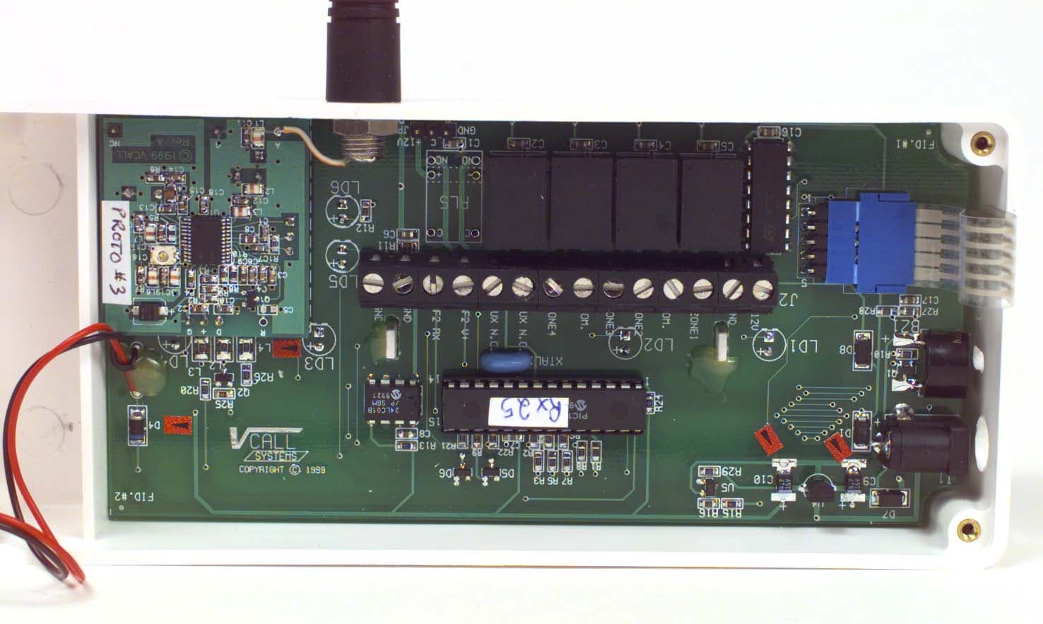
Click to zoom
Application Details
- Equipment Class
- CYY - Communications Receiver used w/Pt 15 Transmitter
- Date of Grant
- Mar 06, 2000
- Application Purpose
- Original Equipment
- Date of Application
- Feb 22, 2000
- Equipment Note
- Car Security RX
- Frequency Range
- 303.89000000 - 303.89000000
- Company
- VCall Systems Inc
- Country
- Canada
Documents & Files
Document Text
Text extracted from the exhibit documents filed with the FCC. Open a document above to read the original.
Users Manual
FOR HOME, BUSINESS, AND ON THE GO VC 1000 VCALL Monitored Wireless Vehicle Intrusion System Instruction Manual CONTENTS: SUMMARY FEATURES INSTRUCTIONS VCALL KEYPAD VCALL DISABLER INFORMATION TO USER WARRANTY FOR HOME, BUSINESS, AND ON THE GO V CALL MONITORED WIRELESS VEHICLE INTRUSION SYSTEM Model VC 1000 SUMMARY The V CALL MO NITERED WIRELESS VEHICLE INTRUSION SYSTEM is comprised of a V EHICLE K IT , VC 2000 which detects the vehicle intrusion and transmit a digital signal of the intrusion; and a K EYPAD , Model VC 100 to announce the intrusion at a remote, preferably monitored, location. The VEHICLE K IT consists of a DIS ABLER Model VC 200 and two TRANSMITTERS , Model VC 300. Each K EYPAD can monitor up to four vehicles (cars). The vehicle must be within range of the K EYPAD . In cases where the Keypad is not within range of the vehicle, the disabling functions will be maintained. Normal equipment installation for V CALL components are: K EYPAD VC100near the home or commercial alarm system Keypad preferably near the parking area, may be stand-alone unit. VEHIC LE K IT DISABLER UNIT VC 200in vehicle cabin, usually under dash TRANSMITTERS VC 300in vehicle cabin, usually at or near front and rear windows The V CALL MO NITORED WIRELESS VEHICLE INTRUSION SYSTEM is primarily designed for vehicle applications in conjunction with home or commercial monitored alarm systems. Other applications provide intrusion detection at campsites, cottages, motels, etc. Modified K EYPADS will provide coverage for automobile dealerships, or large parking areas. 3 V CALL MONITORED WIRELESS VEHICLE INTRUSION SYSTEM Model VC 1000 FEATURES • the V CALL WIRELESS MONITORED INTRUSIO N SYSTEM detects unauthorized vehicle entry. The vehicle is disabled at this time, it will not move. • the “zone” terminology has been adopted from the home and commercial monitored alarm industry. • each zone on the K EYPAD is tuned to an encrypted digital RF transmitter signal, from a single vehicle. An intrusion is indicated by a flashing red LED on the appropriate zone, and an piezo. This intrusion warning can be sent via the K EYPAD to the home or commercial alarm panel to the monitoring station. • the KEYPAD will indicate by the amber LED and the flashing red zone LED if the vehicle has been started by remote starter, in order to avoid hazardous indoor fumes or unknowingly running the vehicle for a long period of time. This information is not sent to the monitoring station. • the KEYPAD may be used as an independent portable stand alone unit. • the DISABLER detector transmits an encrypted digital RF signal to the KEYPAD indicating intrusion. • the responses to the intrusion signal will be in accordance with arrangements made by the client and the monitoring company. • in the vehicle the interior piezo sounds and the interior dash mounted LED flashes. There is no loud disturbing horn. • the DISABLER is compatible with already installed vehicle alarm and remote starter systems. • A selection of detection and disabling devices is available for installation • power supplies: KEYPAD direct connection from the home or business alarm security panel, a 12v adapter, or a 9v battery; DISABLER is supplied from the vehicle’s 12v DC electrical system. • Range up to approximately 500 ft. 4 V CALL MONITORED WIRELESS VEHICLE INTRUSION SYSTEM Model VC 1000 INSTRUCTIONS V CALL KEYPAD Model VC 100 OPERATION The KEYPAD can monitor up to 4 vehicle (cars). Each zone has an LED, a push button, and an output relay. Each zone will monitor one vehicle. 1 The KEYPAD can be turned on and off by pressing the power button (light bulb icon). When powering up the KEYPAD all LEDs are illuminated. The green “power” and amber “car” LEDs lights momentarily. The red zone LEDs light for 3 seconds indicating zones programmed to a vehicle. Zones available for programming are not lit. 2 When an alarm signal is received the appropriate red zone LED will illuminate, the piezo will sound and the output relay will be activated. This is an alarm condition. 3 The alarm condition can be reset by pressing the appropriate zone push button. If the alarm condition is not reset the alarm condition will automatically reset after 5 minutes. The red zone LED will repeatedly blink, once fast followed by a long pause, to indicate a past alarm condition. 4 The KEYPAD can monitor a vehicle being started by remote starter. To indicate that the vehicle is running, the red LED associated with the vehicle’s zone will flash, the car running (car icon) amber LED will be illuminated, and piezo will beep every 4 seconds. The KEYPAD will reset after 30 minutes or when the corresponding zone button is pressed. 5 The KEYPAD may be powered by a 12v adapter, from a home or business an alarm security panel, or a 9v battery. If the receiver is powered by the 9v battery, the output relays will not be activated. PROGRAMMING THE KEYPAD VC 100 To program the receiver 1. Each KEYPAD zone must be programmed to the DISABLER. 2. Press and hold the zone button you wish to assign to the vehicle. 4 seconds later, the red zone LED will turn off. 3. Release the button. The red zone LED will flash quickly to indicate that you have entered programming mode. 4. Within 128 seconds, set DISABLER into alarm. The KEYPAD will beep to indicate that the KEYPAD has been programmed. To erase all codes 1 Press and hold the KEYPAD power key for 8 seconds. The KEYPAD will beep to confirm that all codes have been erased. 5 V CALL MONITORED WIRELESS VEHICLE INTRUSION SYSTEM Model VC 1000 INSTRUCTIONS V CALL DISABLER The DISABLER is an anti-theft system designed to prevent the vehicle from being stolen. It incorporates a built-in starter and auxiliary disabler to disable a fuel pump or similar device. The DISABLER will transmit alarm signals or vehicle starting information to the KEYPAD. The DISABLER incorporates the DISABLER UNIT VC 200 and two TRANSMITTERS , VC 300. DISABLER UNIT MODEL VM 200 OPERATION The DIS ABLER UNIT Model VC 20…
Text truncated - open the document above for the full version.
Attestation Statements
FOR HOME, BUSINESS, AND ON THE GO February 14, 2000 Federal Communicatio ns Commission 7435 Oakland Mills Road Columbia, MD 21046 USA Authority to Act as Agent to the Federal Communications Commission On o ur behalf, I appoint KTL Ottawa to act as agent in the preparation of this application for equipment authorizatio n to the Federal Communications Commission. I certify that submitted Exhibits properly describe the device or system for which equipment authorization is so ught. I also certify that each unit manufactured, imported or marketed, as defined in the Commission’s regulations will have affixed to it a label identical to that submitted for approval with this applicatio n. Dated this21 Day ofFebruary 2000 Agency agreement expiration date:One year from date above By:Gerald Thibault SignaturePrinted Title:President & Ceo Telephone:(613) 860 1460 A pplicant:V CA LL Systems In c.
Cover Letter(s)
FOR HOME, BUSINESS, AND ON THE GO February 14, 2000 Federal Communications Commission: 7435 Oakland Mills Road Columbia, MD 21046 USA Request for Non-Disclosure of Information VCALL SYSTEMS INC. APPLICATION(S) #9R01885 FCC ID: OWKVC100 We request that the FCC keep information contained on our application and detailed on the attached memorandum. Thank you for your consideration of this request. Yours truly, VCALL SYSTEMS INC. Gerard Thibault President and CEO FOR HOME, BUSINESS, AND ON THE GO MEMORANDUM TO:FEDERAL COMMUNICATION COMMISSION FROM:VCALL SYSTEMS INC. SUBJECT:REQUEST FOR NON-DISCLOSURE OF INFORMATION DATE:February 14, 2000 FCC ID: OWKVC100 We wish the following information be withheld from the public: Schematic diagrams Parts lists Photographs Operating instructions Software These items are part of application # 9R01885 We have developed a product, which has various unique processes and hardware. This makes our product unique and in a class of it’s own. The specific items are: 1- Dual transmitters - We use dual transmitters in order to offer a redundant means of transmitting security alarms 2- Software - The software used to control our transmitters is unique in that if one transmitter is disabled the other has the ability to compensate and communicate an alarm signal 3- Keypad control - Our keypad will connect to a standard residential or commercial alarm system in order to communicate an alarm signal. These items are not found in any product in our industry, and are what give us a competitive advantage. Confidentiality would protect our technology for a period of time allowing us to maximize our research to the greatest potential. There are vehicle alarms, and there are monitored residential and commercial alarm systems, but there are no monitored vehicle alarms on the market today. This information will help actual or potential competitors to develop competitive products. We need an advantage in order to establish ourselves in the car alarm market. Vcall Systems inc. has taken many precautions in order to protect our information as listed below 1 – Non disclosure documents for suppliers, Sales agents, Authorized distributors and Contractors. 2 – All information distributed on a need to know basis. 3 - Separate design facilities for hardware and software 4 – Separate manufacturing facilities for hardware 5 – Patents and Copyrights have been applied for on all applicable items 6 – All sensitive files are stored in a vault with extremely restricted access The information requested for non-disclosure is not available to the public, and in it’s combined form is unique to our Company. Except as noted above there hase been no disclosure to third parties. Vcall requests a seven (7) year period for non-disclosure. This represents our estimate for the design, development, manufacturing, and sales of the first and second generation of the product.
ID Label/Location Info
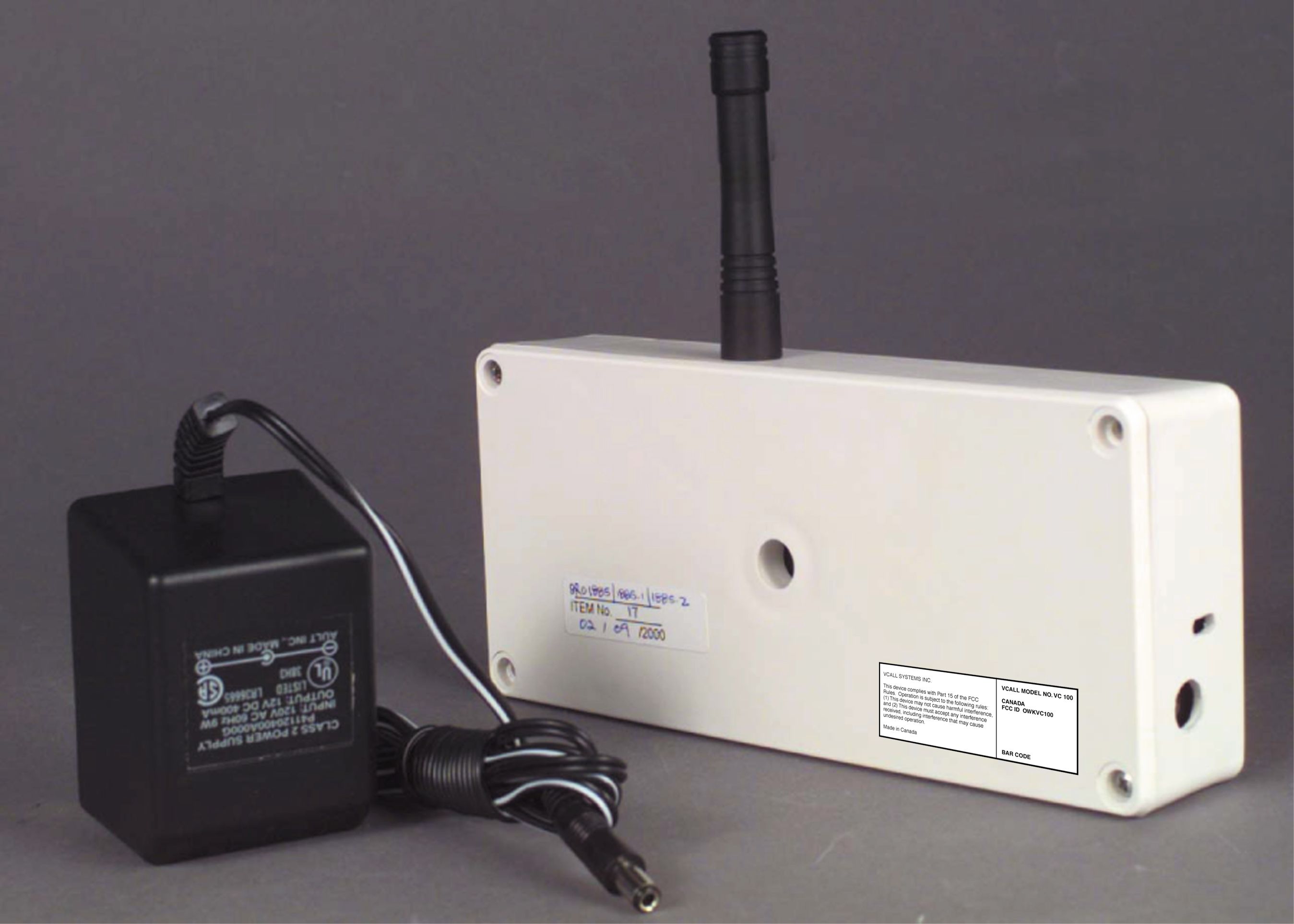
VCALL KEYPADMODEL VC 100 (R ECEIVER ) VCALL SYSTEMS INC. This device complies with Part 15 of the FCC Rules. Operation is subject to the following rules: (1) This device may not cause harmful interference, and (2) This device must accept any interference received, including interference that may cause undesired operation. Made in Canada VCALL MODEL NO. VC 100 CANADA: FCC ID: XXX VC100 B AR C ODE Approximate label size ¾” x 2” Self adhesive label
ID Label/Location Info
VCALL KEYPADMODEL VC 100 (R ECEIVER ) VCALL SYSTEMS INC. This device complies with Part 15 of the FCC Rules. Operation is subject to the following rules: (1) This device may not cause harmful interference, and (2) This device must accept any interference received, including interference that may cause undesired operation. Made in Canada VCALL MODEL NO. VC 100 CANADA: FCC ID: OWKVC100 B AR C ODE Approximate label size ¾” x 2” Self adhesive label
Test Report
Master: ktlPT15BR Date: October 8, 1999 KTL Test Report:9R01885 Applicant:VCALL Systems Inc. 1900 Merivale Road, Suite 202 Nepean, Ontario K2G 4N4 Equipment Under Test:VC 100 Receiver (E.U.T.) FCC ID:OWKVC100 In Accordance With:FCC Part 15, Subpart B Radio Receivers Tested By:KTL Ottawa Inc. 3325 River Road, R.R. 5 Ottawa, Ontario K1V 1H2 Authorized By: R. Grant, Wireless Group Manager Date: Total Number of Pages:18 KTL Ottawa FCC PART 15, SUBPART B RADIO RECEIVERS PROJECT NO.: 9R01885 EQUIPMENT: VC 100 Receiver FCC ID: OWKVC100 Page 2 of 18 Table Of Contents Section 1. Summary of Test Results.............................................................................................3 Section 2. Equipment Under Test (E.U.T.).................................................................................. 5 Section 3. Radiated Emissions ..................................................................................................... 7 Section 4. Powerline Conducted Emissions............................................................................... 12 Section 5. Block Diagrams......................................................................................................... 16 Section 6. Test Equipment List..................................................................................................18 KTL Ottawa FCC PART 15, SUBPART B RADIO RECEIVERS PROJECT NO.: 9R01885 EQUIPMENT: VC 100 Receiver FCC ID: OWKVC100 Page 3 of 18 Section 1.Summary of Test Results General: All measurements are traceable to national standards. These tests were conducted on a sample of the equipment for the purpose of demonstrating compliance with FCC Part 15, Subpart B. Measurement procedure ANSI C63.4-1992 was used for all tests. Radiated Emissions were measured on an open area test site. New SubmissionProduction Unit Class II Permissive ChangePre-Production Unit CYY Equipment Code THIS TEST REPORT RELATES ONLY TO THE ITEM(S) TESTED. THE FOLLOWING DEVIATIONS FROM, ADDITIONS TO, OR EXCLUSIONS FROM THE TEST SPECIFICATIONS HAVE BEEN MADE. See “ Summary of Test Data”. NVLAP LAB CODE: 100351-0 TESTED BY: _____________________________________ DATE: ___________________ Kevin Rose, Test Technician KTL Ottawa Inc. authorizes the above named company to reproduce this report provided it is reproduced in its entirety and for use by the company’s employees only. Any use which a third party makes of this report, or any reliance on or decisions to be made based on it, are the responsibility of such third parties. KTL Ottawa Inc. accepts no responsibility for damages, if any, suffered by any third party as a result of decisions made or actions based on this report. This report applies only to the items tested. KTL Ottawa FCC PART 15, SUBPART B RADIO RECEIVERS PROJECT NO.: 9R01885 EQUIPMENT: VC 100 Receiver FCC ID: OWKVC100 Page 4 of 18 Summary Of Test Data Name Of TestPara. No.Results Antenna Conducted Emissions15.111Not Applicable Radiated Emissions15.109Complies Powerline Conducted Emissions15.107Complies Footnotes For N/A’s: Non-detachable antenna. Test Conditions: Indoor Temperature: 21 °C Humidity:32 % Outdoor Temperature: 10 °C Humidity:18 % KTL Ottawa FCC PART 15, SUBPART B RADIO RECEIVERS PROJECT NO.: 9R01885 EQUIPMENT: VC 100 Receiver FCC ID: OWKVC100 Page 5 of 18 Section 2.Equipment Under Test (E.U.T.) Manufacturer:VCALL Systems Model No.:VC 100 Serial No.:None Date Received In Laboratory: February 9, 2000 KTL Identification No.: Item #17 Equipment Details Frequency Range:303.89 MHz Number of Channels:1 Operating Frequency(ies) of Sample: 303.89 MHz Crystal Frequency(ies):48.17 MHz Primary Power Requirement:120 VAC to 12 Vdc XFormer KTL Ottawa FCC PART 15, SUBPART B RADIO RECEIVERS PROJECT NO.: 9R01885 EQUIPMENT: VC 100 Receiver FCC ID: OWKVC100 Page 6 of 18 Configuration of the Equipment Under Test Receiver Antenna 120 VAC 60 Hz KTL Ottawa FCC PART 15, SUBPART B RADIO RECEIVERS PROJECT NO.: 9R01885 EQUIPMENT: VC 100 Receiver FCC ID: OWKVC100 Page 7 of 18 Section 3.Radiated Emissions NAME OF TEST: Radiated EmissionsPARA. NO.: 15.109(a) TESTED BY: Kevin RoseDATE: February 9, 2000 Minimum Standard: Frequency(MHz)Field Strength (dB μ μμ μ V/m @ 3m) 30 - 8840.0 88 - 21643.5 216 - 96046.0 Above 96054.0 Test Results: Complies. The worst-case emission level is 34.6 dBμV/m @ 3m at 293.12 MHz. This is 11.4 dB below the specification limit. Measurement Data: See attached table. For super-regenerative receivers the receiver is cohered using a signal generator and dipole antenna. Handheld equipment and equipment not designed to be mounted in any fixed orientation, the E.U.T. is tested in three orthogonal axis to obtain worst case results. KTL Ottawa FCC PART 15, SUBPART B RADIO RECEIVERS PROJECT NO.: 9R01885 EQUIPMENT: VC 100 Receiver FCC ID: OWKVC100 Page 8 of 18 Test Data - Radiated Emissions Test Distance (meters) : 3 Range : A Towe r Re ce ive r: ESVP RBW(kHz ): 120 Detector: Q-Peak Fre q. (M Hz) Ant. * Pol. (V/H) Ant. HGT. (m) Table (deg.) RCVD Signal (dB μ μμ μ V/m) Ant. Factor (dB)** Amp. Gain (dB)*** Dist. Corr. (dB) Fie ld Strength (dB μ μμ μ V/m) Limit (dB μ μμ μ V/m) Margin (dB) 293.12E/D312.821.834.646.011.4 293.12E/D312.321.834.146.011.9 586.25E/D46.730.036.746.09.3 586.25E/D46.730.036.746.09.3 Notes: B/C = Biconical, B/L = Biconilog, L/P = Log-Periodic, H = Horn, D/P = Dipole * Re-measured using dipole antenna. ( ) Denotes failing emission level. (1) 120 kHz, Q-Peak, (2) 10 kHz, Peak, (3) 100 kHz RGW, 300 kHz VBW, Peak, (4) 300 kHz RBW, 1 MHz VBW, Peak, (5) 1 MHz RBW, 3 MHz VBW, Peak, (6) 1 MHz RBW, 10 Hz VBW, Peak KTL Ottawa FCC PART 15, SUBPART B RADIO RECEIVERS PROJECT NO.: 9R01885 EQUIPMENT: VC 100 Receiver FCC ID: OWKVC100 Page 9 of 18 Radiated Photographs(Worst Case Configuration) Front View Rear View KTL Ottawa FCC PART 15, SUBPART B RADIO RECEIVERS PROJECT NO.: 9R01885 EQUIPMENT: VC 100 Receiver FCC ID: OWKVC100 Page 10 of 18 KTL Ottawa FCC PART 15, SUBPART B RADIO RECEIVERS PROJECT NO…
Text truncated - open the document above for the full version.
Test Report
Master: ktlPT15BR Date: October 8, 1999 KTL Test Report:9R01885 Applicant:VCALL Systems Inc. 1900 Merivale Road, Suite 202 Nepean, Ontario K2G 4N4 Equipment Under Test:VC 100 Receiver (E.U.T.) FCC ID:OWKVC100 In Accordance With:FCC Part 15, Subpart B Radio Receivers Tested By:KTL Ottawa Inc. 3325 River Road, R.R. 5 Ottawa, Ontario K1V 1H2 Authorized By: R. Grant, Wireless Group Manager Date: Total Number of Pages:18 KTL Ottawa FCC PART 15, SUBPART B RADIO RECEIVERS PROJECT NO.: 9R01885 EQUIPMENT: VC 100 Receiver FCC ID: OWKVC100 Page 2 of 18 Table Of Contents Section 1. Summary of Test Results.............................................................................................3 Section 2. Equipment Under Test (E.U.T.).................................................................................. 5 Section 3. Radiated Emissions ..................................................................................................... 7 Section 4. Powerline Conducted Emissions............................................................................... 12 Section 5. Block Diagrams......................................................................................................... 16 Section 6. Test Equipment List..................................................................................................18 KTL Ottawa FCC PART 15, SUBPART B RADIO RECEIVERS PROJECT NO.: 9R01885 EQUIPMENT: VC 100 Receiver FCC ID: OWKVC100 Page 3 of 18 Section 1.Summary of Test Results General: All measurements are traceable to national standards. These tests were conducted on a sample of the equipment for the purpose of demonstrating compliance with FCC Part 15, Subpart B. Measurement procedure ANSI C63.4-1992 was used for all tests. Radiated Emissions were measured on an open area test site. New SubmissionProduction Unit Class II Permissive ChangePre-Production Unit CYY Equipment Code THIS TEST REPORT RELATES ONLY TO THE ITEM(S) TESTED. THE FOLLOWING DEVIATIONS FROM, ADDITIONS TO, OR EXCLUSIONS FROM THE TEST SPECIFICATIONS HAVE BEEN MADE. See “ Summary of Test Data”. NVLAP LAB CODE: 100351-0 TESTED BY: _____________________________________ DATE: ___________________ Kevin Rose, Test Technician KTL Ottawa Inc. authorizes the above named company to reproduce this report provided it is reproduced in its entirety and for use by the company’s employees only. Any use which a third party makes of this report, or any reliance on or decisions to be made based on it, are the responsibility of such third parties. KTL Ottawa Inc. accepts no responsibility for damages, if any, suffered by any third party as a result of decisions made or actions based on this report. This report applies only to the items tested. KTL Ottawa FCC PART 15, SUBPART B RADIO RECEIVERS PROJECT NO.: 9R01885 EQUIPMENT: VC 100 Receiver FCC ID: OWKVC100 Page 4 of 18 Summary Of Test Data Name Of TestPara. No.Results Antenna Conducted Emissions15.111Not Applicable Radiated Emissions15.109Complies Powerline Conducted Emissions15.107Complies Footnotes For N/A’s: Non-detachable antenna. Test Conditions: Indoor Temperature: 21 °C Humidity:32 % Outdoor Temperature: 10 °C Humidity:18 % KTL Ottawa FCC PART 15, SUBPART B RADIO RECEIVERS PROJECT NO.: 9R01885 EQUIPMENT: VC 100 Receiver FCC ID: OWKVC100 Page 5 of 18 Section 2.Equipment Under Test (E.U.T.) Manufacturer:VCALL Systems Model No.:VC 100 Serial No.:None Date Received In Laboratory: February 9, 2000 KTL Identification No.: Item #17 Equipment Details Frequency Range:303.89 MHz Number of Channels:1 Operating Frequency(ies) of Sample: 303.89 MHz Crystal Frequency(ies):48.17 MHz Primary Power Requirement:120 VAC to 12 Vdc XFormer KTL Ottawa FCC PART 15, SUBPART B RADIO RECEIVERS PROJECT NO.: 9R01885 EQUIPMENT: VC 100 Receiver FCC ID: OWKVC100 Page 6 of 18 Configuration of the Equipment Under Test Receiver Antenna 120 VAC 60 Hz KTL Ottawa FCC PART 15, SUBPART B RADIO RECEIVERS PROJECT NO.: 9R01885 EQUIPMENT: VC 100 Receiver FCC ID: OWKVC100 Page 7 of 18 Section 3.Radiated Emissions NAME OF TEST: Radiated EmissionsPARA. NO.: 15.109(a) TESTED BY: Kevin RoseDATE: February 9, 2000 Minimum Standard: Frequency(MHz)Field Strength (dB μ μμ μ V/m @ 3m) 30 - 8840.0 88 - 21643.5 216 - 96046.0 Above 96054.0 Test Results: Complies. The worst-case emission level is 34.6 dBμV/m @ 3m at 293.12 MHz. This is 11.4 dB below the specification limit. Measurement Data: See attached table. For super-regenerative receivers the receiver is cohered using a signal generator and dipole antenna. Handheld equipment and equipment not designed to be mounted in any fixed orientation, the E.U.T. is tested in three orthogonal axis to obtain worst case results. KTL Ottawa FCC PART 15, SUBPART B RADIO RECEIVERS PROJECT NO.: 9R01885 EQUIPMENT: VC 100 Receiver FCC ID: OWKVC100 Page 8 of 18 Test Data - Radiated Emissions Test Distance (meters) : 3 Range : A Towe r Re ce ive r: ESVP RBW(kHz ): 120 Detector: Q-Peak Fre q. (M Hz) Ant. * Pol. (V/H) Ant. HGT. (m) Table (deg.) RCVD Signal (dB μ μμ μ V/m) Ant. Factor (dB)** Amp. Gain (dB)*** Dist. Corr. (dB) Fie ld Strength (dB μ μμ μ V/m) Limit (dB μ μμ μ V/m) Margin (dB) 293.12E/D312.821.834.646.011.4 293.12E/D312.321.834.146.011.9 586.25E/D46.730.036.746.09.3 586.25E/D46.730.036.746.09.3 Notes: B/C = Biconical, B/L = Biconilog, L/P = Log-Periodic, H = Horn, D/P = Dipole * Re-measured using dipole antenna. ( ) Denotes failing emission level. (1) 120 kHz, Q-Peak, (2) 10 kHz, Peak, (3) 100 kHz RGW, 300 kHz VBW, Peak, (4) 300 kHz RBW, 1 MHz VBW, Peak, (5) 1 MHz RBW, 3 MHz VBW, Peak, (6) 1 MHz RBW, 10 Hz VBW, Peak KTL Ottawa FCC PART 15, SUBPART B RADIO RECEIVERS PROJECT NO.: 9R01885 EQUIPMENT: VC 100 Receiver FCC ID: OWKVC100 Page 9 of 18 Radiated Photographs(Worst Case Configuration) Front View Rear View KTL Ottawa FCC PART 15, SUBPART B RADIO RECEIVERS PROJECT NO.: 9R01885 EQUIPMENT: VC 100 Receiver FCC ID: OWKVC100 Page 10 of 18 KTL Ottawa FCC PART 15, SUBPART B RADIO RECEIVERS PROJECT NO…
Text truncated - open the document above for the full version.
Contact Information
Applicant
Gerard Thibault(President, CEO)
613-860-1460Fax: 613-860-1461
Technical Contact
Non-Technical Contact
VCALL SYSTEMS INC.GERARD THIBAULT
613-860-1460
Test Firm
Nemko Canada Inc.Stuart Beck
Technical Specifications
| # | Rule Parts | Frequency Range | Power Output |
|---|---|---|---|
| 1 | 15B | 303.89 MHz - 303.89 MHz | - |
Other Applications from VCall Systems Inc
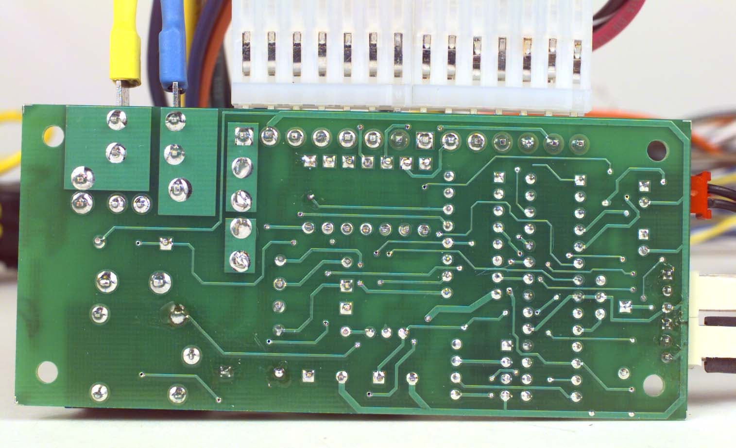
OWKVC300
Mar 06, 2000Car Security TX
Equipment Class
DSC - Part 15 Security/Remote Control Transmitter