OX3PD70ATouchscreen Flatpanel Display
Dynapro Technologies Inc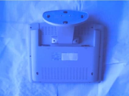
Click to zoom
Application Details
- Equipment Class
- JBP - Part 15 Class B Computing Device Peripheral
- Date of Grant
- Jun 21, 2000
- Application Purpose
- Original Equipment
- Date of Application
- Mar 23, 2000
- Equipment Note
- Touchscreen Flatpanel Display
- Company
- Dynapro Technologies Inc
- Country
- Canada
Documents & Files
Document Text
Text extracted from the exhibit documents filed with the FCC. Open a document above to read the original.
Users Manual
Manual Excerpt: (Located prominently inside the front cover of the User’s Manual) Note: This equipment has been tested and found to comply with the limits for a Class B digital device, pursuant to part 15 of the FCC Rules and ICES 03. These limits are designed to provide reasonable protection against harmful interference in a residential installation. This equipment generates, uses and can radiate radio frequency energy and, if not in-stalled and used in accordance with the instructions, may cause harmful interference to radio communications. However, there is no guarantee that interference will not occur in a particular installation. If this equipment does cause harmful interference to radio or television reception, which can be determined by turning the equipment off and on, the user is encouraged to try to correct the interference by one or more of the following measures: • Reorient or relocate the receiving antenna. • Increase the separation between the equipment and receiver. • Connect the equipment into an outlet on a circuit different from that to which the receiver is connected. • Consult the dealer or an experienced radio/TV technician for help. Caution: Changes or modifications to this equipment, not expressly approved by the manufacturer could void the user's authority to operate the equipment.
Block Diagram
PD-70FA Block Diagram Display Panel Touchscreen Touchscreen Controller Display Controller Backlight Backlight Invertor Power Regulator DB9 Serial Port DB15 VG A Port DC Power Input AC Power Input Power Supply Module Display Unit
External Photos
PD-70FA External Photos Front View Rear View, Including label location
Internal Photos
PD-70FA Internal Photo
Operational Description
PD-70FA Functional Description The PD-40 A is a flat panel display device with intergated touchscreen. The flat panel display section utilizes a standard VGA type analogue RGB input, and converst the signal to digital format for the display panel. At the highest resolution (XGA Mode) and 75 Hz Refresh rate, the clock signals are as follows: Horizontal scan rate 60 KHz Vertital scan rate 75 Hz VCLK 78.75 MHz These frequencies are supplied to display panel from the Display Controller Circuit, and generated by on-board VCOs and Phased Locked Loops. The Touch controller uses a low freqcueny (PCLK 4.0 MHz) microprocessor to scan the resistive element for touch coordinates. The power regulation uses solid state DC-DC convertors to provide the logic and required circuit voltages, and a backlight invertor operates at about 75 KHz to provide the voltages for the backlight of the dipslay panel. PD-70FA Block Diagram Display Panel: VCLK Max: 78.75 MHz Touchscreen Touchscreen Controller Display Controller VCLK Max: 78.75 MHz Backlight Backlight Invertor Power Regulator DB9 Serial Port DB15 VGA Port DC Power Input AC Power Input Power Supply Module Display Unit
Test Report
Dynapro Technologies Inc. Touchpro PD-70FA Monitor FCC Report of Measurements Rev. 1.0, March 24, 2000 Page 1 of 7 Dynapro Technologies Touchpro PD-70FA Report of Measurements per FCC CFR47 Part 15/B Revision 1.0 March 25, 2000 Prepared by: R.E.Stirling ________________________________ 03/30/00 ___________________ Robert Stirling, P.EngDate Protocol Labs, Abbotsford B.C., Canada FCC Registration Number 96437 Industry Canada Registration Number IC3384 Dynapro Technologies Inc. Touchpro PD-70FA Monitor FCC Report of Measurements Rev. 1.0, March 24, 2000 Page 2 of 7 Testing Details TESTED BY: Robert Stirling TEST CONDITIONS:Temperature and Humidity: 20 C, 40% TEST VOLTAGE: 120 VAC, 60 Hz Test Facilities Protocol Labs 28945 McTavish Rd. Abbotsford B.C., Canada, V4X 2E7 FCC Registration Number 96437 Industry Canada Registration Number IC3384 Test Equipment List: DeviceModel NumberSerial No.Last Cal. Next Cal AntennaEM CO 3141 Bilog112718/12/9818/06/00 LISNSolar 8012-50-R-24-BNC86309202/18/0002/18/01 Spectrum AnalyzerHewlett Packard 8566B2241A0210212/21/9912/21/00 RF-PreselectorHewlett Packard 85685A3107A0122212/21/9912/21/00 Quasi-Peak Adapter Hewlett Packard 85650A2043A0024012/21/9912/21/00 TowerRhientech LabsCustom TurntableProtocolCustom Equipment Under Test: The test system:EUTTouchscreen Display Monitor Manufacturer Dynapro Technologies Part NumberPD-70FA2 Serial Number ENG 02 HOST:Notebook PC Manufacturer Compaq Part NumberPresario 1255 Serial Number 1V93CFK6226S Cabling: Cable# of conductorsShieldedFerrite Host Pow er Cable2NoY es EUT Power Cable2NoYes Serial Cable9YesNo VGA Cable3YesYes - 2 Test Setup:The EUT and Host were interconnected by the cabling supplied with each unit, and the drivers were installed to active the touchscreen. It was determined that the worst case radiated emissions were using the 600 by 800 resolution setting. A test program was executed, which continuously scrolled a continual string of the ASCII characters ‘55’ on the screen. Dynapro Technologies Inc. Touchpro PD-70FA Monitor FCC Report of Measurements Rev. 1.0, March 24, 2000 Page 3 of 7 Summary of Testing: Tests were conducted on a sample of the equipment for the purpose of demonstrating compliance with FCC Part 15B- Unintentional Radiators, and ICES 03 to Class B limits. Both the Radiated and Power Line Conducted Emission tests were performed using measurement procedure outlined in the above standards. Manufacturer’s responsibilities Markings According to FCC Section 15.19, and ICES 003, a statement similar to the following must be included on an identification label, which also uniquely identifies the Manufactured date, either explicitly or through a Serial number etc: “This equipment complies with Part 15 of the FCC Rules, and Industry Canada's ICES 03 for a Class B Digital Device. Operation is subject to the following two conditions: 1) That this device does not cause harmful interference, and 2) this device must accept any interference received, including interference that may cause undesired operation.” Additionally, If the manufacturer markets product to Quebec, the following supplemental information should be added to the label : "Cet Apparreil numerique de la Classe B respecte toutes les exigences du Reglement sur le material broilleur du Canada." Labeling According to FCC Section 15.105, and ICES 003, the following statement must be included in a prominent location in the User's Manual: Note: This equipment has been tested and found to comply with the limits for a Class B digital device, pursuant to part 15 of the FCC Rules and ICES 03. These limits are designed to pro-vide reasonable protection against harmful interference in a residential installation. This equipment generates, uses and can radiate radio frequency energy and, if not in-stalled and used in accordance with the instructions, may cause harmful interference to radio communications. However, there is no guarantee that interference will not occur in a particular installation. If this equipment does cause harmful interference to radio or television reception, which can be determined by turning the equipment off and on, the user is encouraged to try to correct the interference by one or more of the following measures: —Reorient or relocate the receiving antenna. —Increase the separation between the equipment and receiver. —Connect the equipment into an outlet on a circuit different from that to which the receiver is connected. —Consult the dealer or an experienced radio/TV technician for help. It is also required according to FCC Part B Section 15.21, that a caution be included such as: Caution: Changes or modifications to this equipment, not expressly approved by the manufacturer could void the user's authority to operate the equipment. Dynapro Technologies Inc. Touchpro PD-70FA Monitor FCC Report of Measurements Rev. 1.0, March 24, 2000 Page 4 of 7 Part 1: Conducted Emission Testing DATE:February 18, 2000 TEST STANDARD:FCC CFR47, Part 15, Subpart B RESOLUTION BANDWIDTH:9 kHz DEVICE DESCRIPTIONS:As described in the Equipment Under Test Section, above. TEST SETUP:The EUT was connected to the conducted emissions LISN apparatus, and the host was connected to a second LISN, to provide isolation. METHOD OF MEASUREMENT:Measurements were made using a spectrum analyzer with 10kHz RBW, Peak detector. Any emissions that are close to the limit are measured using a test receiver with 10kHz bandwidth, CISPR Quasi-Peak detector. CABLING DETAILS: The EUT was Set up using the manufacturer's specified normal cabling configuration. MINIMUM STANDARD:Class B Limits: Frequency (MHz)Maximum Level (dBuV) Maximum Level (dBuV) Quasi-PeakAverage 0.45 – 30.061.058.0 MEASUREMENT DATA: See Appendix A for Plots, FCC Class B limits are Marked. EMISSIONS DATA: See Tables 1 and 2 in Appendix A for corresponding frequencies. PERFORMANCE:Complies. Dynapro Technologies Inc. Touchpro PD-70FA Monitor FCC Report of Measurements Rev. 1.0, March 24, 2000 Page 5 of 7 Part 2: R…
Text truncated - open the document above for the full version.
Test Report
Appendix A: PD-70FA Conducted Plots Line 1 Line 2
Test Setup Photos
Appendix B: Photos Emissions Test Setup Front View Dynapro PD-70FA 02/18/00 Emissions Test Setup Rear View Dynapro PD-70FA 02/18/00
Contact Information
Applicant
Robert E Stirling(Compliance Engineer)
Technical Contact
Non-Technical Contact
Dynapro Technologies Inc.Lewis H Levasseur
[email protected]604 521 3962
Test Firm
Protocol LabsRobert Stirling
Technical Specifications
| # | Rule Parts | Frequency Range | Power Output |
|---|---|---|---|
| 1 | 15B | - | - |
Other Applications from Dynapro Technologies Inc
OX3PD50A
Jun 21, 2000Touchscreen Flatpanel Display
Equipment Class
JBP - Part 15 Class B Computing Device Peripheral