OXA9200100Flashlight attachable metal detector for law enfor
Sensor Devices, Inc.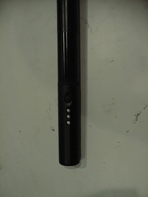
Click to zoom
Application Details
- Equipment Class
- DCD - Part 15 Low Power Transmitter Below 1705 kHz
- Date of Grant
- Apr 03, 2000
- Application Purpose
- Original Equipment
- Date of Application
- Mar 09, 2000
- Equipment Note
- Flashlight attachable metal detector for law enfor
- Frequency Range
- 0.46000000 - 0.47000000
- Company
- Sensor Devices, Inc.
- Country
- United States
Documents & Files
Document Text
Text extracted from the exhibit documents filed with the FCC. Open a document above to read the original.
Users Manual
Appendix B:User Manual - Front Page Project: 00RT3974Underwriters Laboratories, Inc.Issued: 03/02/00 File: MC1239Test Report on Electromagnetic CompatibilityPage 2 of 5 Test Report: 000149 Appendix B (cont):User Manual - Page 2 Project: 00RT3974Underwriters Laboratories, Inc.Issued: 03/02/00 File: MC1239Test Report on Electromagnetic CompatibilityPage 3 of 5 Test Report: 000149 Appendix B (cont):User Manual - Page 3 Project: 00RT3974Underwriters Laboratories, Inc.Issued: 03/02/00 File: MC1239Test Report on Electromagnetic CompatibilityPage 4 of 5 Test Report: 000149 Appendix B (cont):User Manual - Page 4 Project: 00RT3974Underwriters Laboratories, Inc.Issued: 03/02/00 File: MC1239Test Report on Electromagnetic CompatibilityPage 5 of 5 Test Report: 000149 Appendix B (cont):User Manual - Page 5
External Photos
EUT Information:EUT Photograph Project: 00RT3974Underwriters Laboratories, Inc.Issued: 03/02/00 File: MC1239Test Report on Electromagnetic CompatibilityPage 2 of 3 Test Report: 000149 EUT Information:EUT Photograph - Metal Detector Project: 00RT3974Underwriters Laboratories, Inc.Issued: 03/02/00 File: MC1239Test Report on Electromagnetic CompatibilityPage 3 of 3 Test Report: 000149 EUT Information:EUT Photograph - Circuit Board Construction
ID Label/Location Info
EUT Information:Contruction Drawing - FCC Label *Due to constraints of a suitable place to position a label with the FCC Statement, only the FCC ID is on the label. The FCC statement is placed in the user manual attached in Appendix B. Actual label is approximately 1” x 1”. Project: 00RT3974Underwriters Laboratories, Inc.Issued: 03/02/00 File: MC1239Test Report on Electromagnetic CompatibilityPage 2 of 2 Test Report: 000149 EUT Information:EUT Photograph - Label Placement
ID Label/Location Info
EUT Information:Contruction Drawing - FCC Label *Due to constraints of a suitable place to position a label with the FCC Statement, only the FCC ID is on the label. The FCC statement is placed in the user manual attached in Appendix B. Actual label is approximately 1” x 1”. Sensor Devices, Inc. Model: 9200100 FCC ID: OXA9200100 Made in the USA Use 9V Alkaline Battery Only Patents Pending
ID Label/Location Info
Project: 00RT3974Underwriters Laboratories, Inc.Issued: 03/02/00 File: MC1239Test Report on Electromagnetic CompatibilityPage2 of 2 Test Report: 000149 EUT Information:EUT Photograph - Label Placement
Schematics
EUT Information:Block Diagram
Test Report
Project: 00RT3974 File: MC1239 Report: 000149 Date: March 02, 2000 Model: 9200100 Test Report On Electromagnetic Compatibility Testing Sensor Devices, Inc. Madison, AL USA Copyright 2000 Underwriters Laboratories Inc. Underwriters Laboratories Inc. authorizes the above-named company to reproduce this Report provided it is reproduced in its entirety. Project: 00RT3974Underwriters Laboratories, Inc.Issued: 03/02/00 File: MC1239Test Report on Electromagnetic CompatibilityPage 2 of 33 Test Report: 000149 Test Report Details: Tests Performed By: Underwriters Laboratories Inc. 12 Laboratory Drive Research Triangle Park, NC 27709 Tests Performed For: Sensor Devices, Inc. 106 Mystic Way Madison, AL 35757 USA Applicant Contact: Mr. Mike Sutherlin (256) 797-0255 - FAX Test Report Number: 000149 Test Report Date: March 02, 2000 Product Type: eScan Low-Powered Transmitter Model Number: 9200100 Sample Serial Number: Sample Tag Number: S00LB058 EUT Category: Special EUT Type: Hand Held Sample Receive Date: February 21, 2000 Testing Start Date: February 21, 2000 Date Testing Complete: February 21, 2000 Underwriters Laboratories Inc. reports apply only to the specific samples tested under stated test conditions. All samples tested were in good operating condition throughout the entire test program. It is the manufacturer's responsibility to assure that additional production units of this model are manufactured with identical electrical and mechanical components. Underwriters Laboratories Inc. shall have no liability for any deductions, inferences or generalizations drawn by the client or others from Underwriters Laboratories Inc. issued reports. This report shall not be used to claim, constitute or imply product certification, approval, or endorsement by NVLAP or any agency of the US government. This report may contain data which is not covered by the NVLAP accreditation. Only data which is noted under Remarks of Summary of Testing as being NVLAP Accredited Data can be considered to be covered by the NVLAP accreditation. Project: 00RT3974Underwriters Laboratories, Inc.Issued: 03/02/00 File: MC1239Test Report on Electromagnetic CompatibilityPage 3 of 33 Test Report: 000149 Summary of Testing: TestTest NameComplyDoes Not See #Test Requirement/SpecificationComplyRemark 1Radiated Disturbance Emissions - 0.01 to 30 MHz Electric FieldX- 47 CFR Part 15, Subpart C / 47 CFR Part 15, Subpart C, Section 15.209 2Radiated Disturbance Emissions - 30 to 1000 MHz Electric FieldX- 47 CFR Part 15, Subpart C / 47 CFR Part 15, Subpart C, Section 15.209 Remarks: 1)Initial scan at the EUT’s transmit frequency was performed with the EUT horizontal and the EUT vertical on the test table. From these scans it was determined that the strongest field strength was measured with the EUT horizontal. The remaining measurements were performed with the EUT lying horizontal on the measurement table. Conclusion: The EUT was determined to comply with FCC Part 15 Section 15.209. This data can also be considered applicable to Canadian Standard RSS-210 Sections 4.6.1 and 13.0. The tests listed in the Summary of Testing section of this report have been performed and the results recorded by Underwriters Laboratories Inc. in accordance with the procedures stated in each test requirement and specification. The test list was determined by the Applicant as being applicable to the Equipment Under Test. As a result, the subject product has been verified to comply or not comply as noted in the Summary of Testing with each test specification. The test results relate only to the items tested. Project: 00RT3974Underwriters Laboratories, Inc.Issued: 03/02/00 File: MC1239Test Report on Electromagnetic CompatibilityPage 4 of 33 Test Report: 000149 Test Facilities: Test Location A) 10-Meter Anechoic Chamber (Industry Canada - IC 2953, NVLAP - 200246-0, VCCI - R-722) Constructed by Lindgren RF Enclosures, this room consists of a 17.9 by 12 by 8.3 m (inside clearance) shielded room lined with TDK absorber material. The walls, floor (conducting ground plane) and ceiling are constructed of double sided galvanized sheet steel supported by 19 mm thick particle board. The interior walls and ceiling are covered with 10 by 10 cm, 4.6 mm thick ferrite tiles and partially covered with polystyrene absorber cones. Removable floor tiles and cones covering the floor between the EUT and antenna are provided when RF immunity testing is performed. Room is provided with a 4.0 m diameter embedded turntable and a 1.2 by 2.1 m and 2.4 by 2.4 m double knife edge doors for access. Also, the room is fed electrical EUT power via permanently installed filters and is provided with a permanently mounted video surveillance camera. A remotely controllable antenna mast is located in the room for positioning the measuring antenna from 1 to 4 m above the ground plane. Test Location B) Compact Anechoic Chamber Constructed by Lindgren RF Enclosures, this room consists of a 6 by 3 by 2.9 m (inside clearance) shielded room lined with TDK absorber material. The walls, floor (conducting ground plane) and ceiling are constructed of double sided galvanized sheet steel supported by 19 mm thick particle board. The interior walls and ceiling are covered with 10 by 10 cm, 4.6 mm thick ferrite tiles and partially covered with polystyrene absorber cones. Removable floor tiles and cones covering the floor between the EUT and antenna are provided when RF immunity testing is performed. Room is provided with a 1.5 m diameter embedded turntable and a 1.2 by 2.1 m double knife edge door for access. Also, the room is fed electrical EUT power via permanently installed filters and is provided with a permanently mounted video surveillance camera. Test Location C) RF Shielded Room (VCCI - C-744, NVLAP - 200246-0) Constructed by Lindgren RF Enclosures, this room consists of a 7.3 by 4.3 by 2.7 m (inside clearance) shielded room. The walls, floor (conducting ground plane) and ceiling are constructed of double sided …
Text truncated - open the document above for the full version.
Contact Information
Applicant
Michael D Sutherlin(President)
Technical Contact
Sensor Devices, Inc.Michael D Sutherlin
[email protected]256-797-0255
106 Mystic Way · Madison, Alabama · United States
Non-Technical Contact
Sensor Devices, Inc.Michael D Sutherlin
[email protected]256-797-0255
Test Firm
UL LLCRick Titus
Technical Specifications
| # | Rule Parts | Frequency Range | Power Output |
|---|---|---|---|
| 1 | 15C | 0.46 MHz - 0.47 MHz | - |