OXBRF58-015.8GHZ PULSE RF RANGEFINDER
LAWRENCE LIVERMORE NATIONAL LABORATORY
Click to zoom
Application Details
- Equipment Class
- FDS - Part 15 Field Disturbance Sensor
- Date of Grant
- Aug 17, 2000
- Application Purpose
- Original Equipment
- Date of Application
- Mar 12, 2000
- Equipment Note
- 5.8GHZ PULSE RF RANGEFINDER
- Frequency Range
- 5785.00000000 - 5815.00000000
- Country
- United States
Documents & Files
Document Text
Text extracted from the exhibit documents filed with the FCC. Open a document above to read the original.
Users Manual
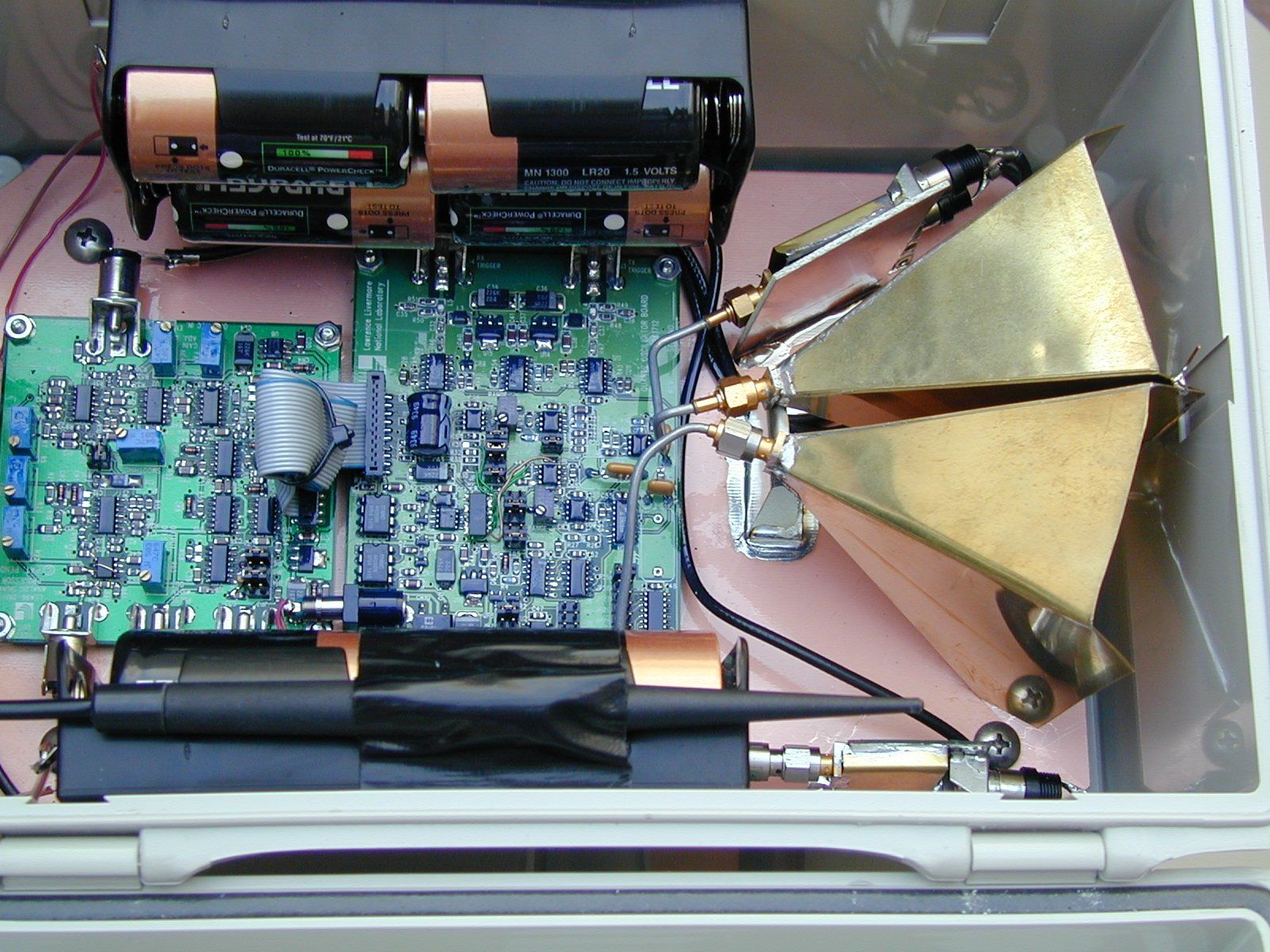
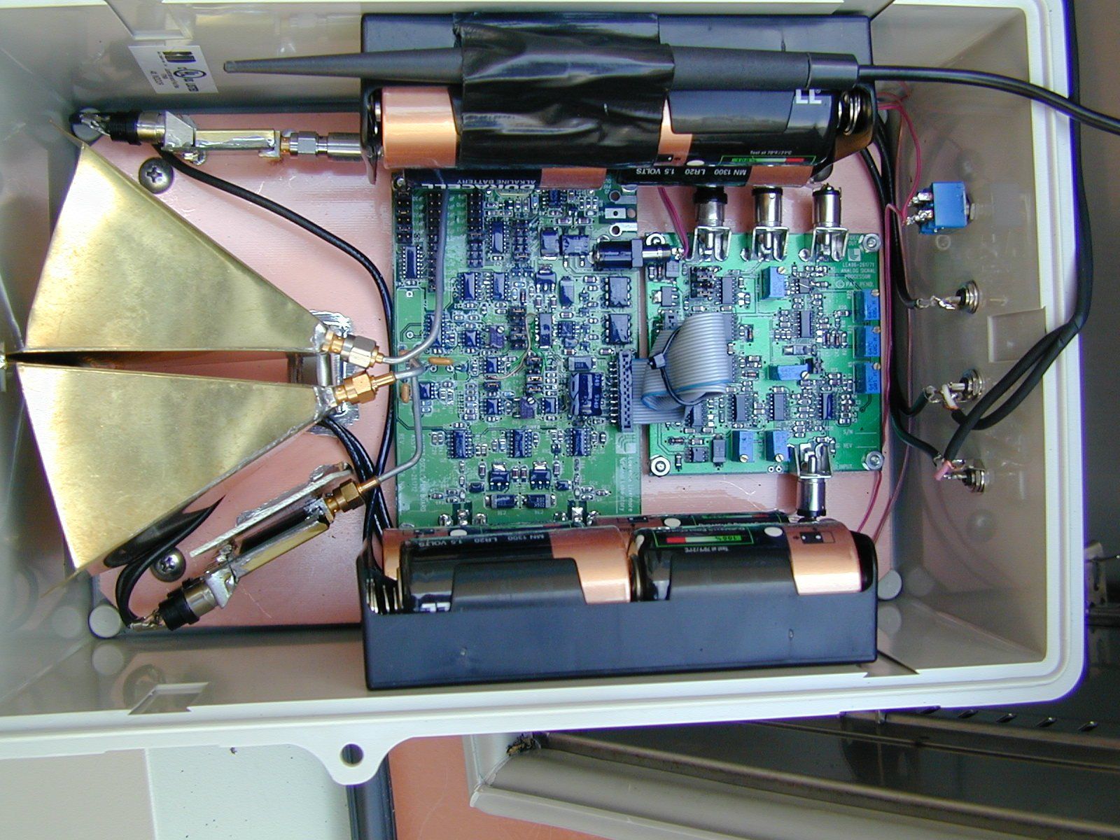
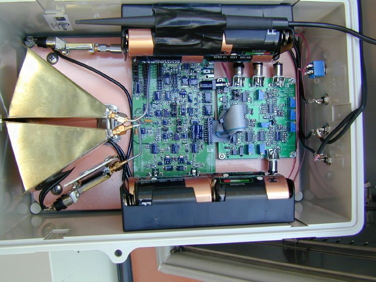
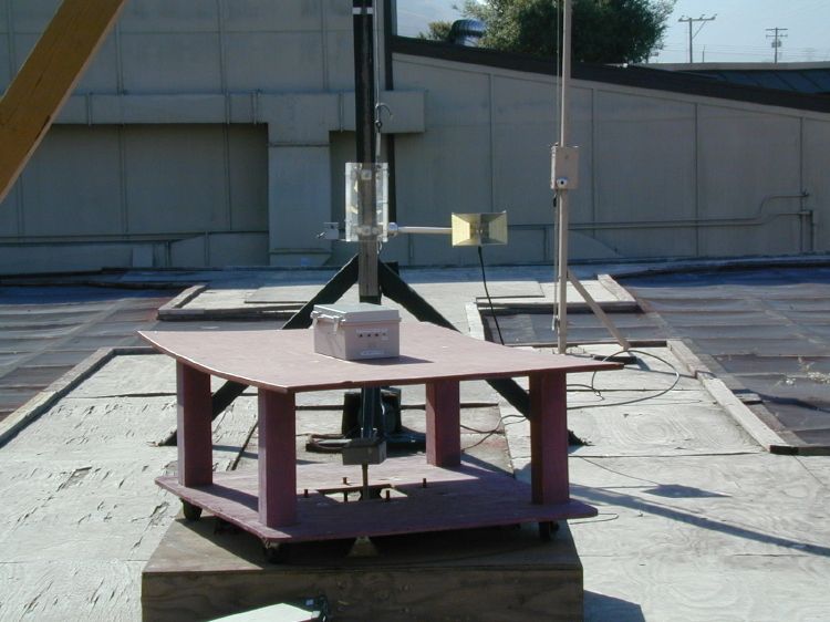
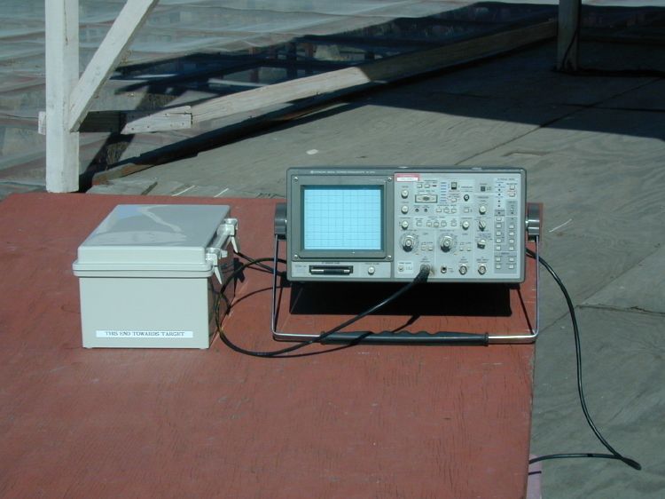
Lawrence Livermore National Laboratory Radar Rangefinder Demo Unit Model RF58-01 Rangefinder Radar Operation/Installation Instructions Description The RF58-01 rangefinder radar is a low-power, high-resolution, pulse-echo radar operating at 5.8 GHz. Its intended purpose is to very accurately measure relative changes in liquid level height. The unit is housed in plastic NEMA case, which is about 8-inches by 11-inches by 6-inches deep and uses 12VDC (batteries) for self-contained operation. Installation Proper operation of the RF58-01 rangefinder is dependent upon installation in a suitable environment and use of sound installation practices. This radar-based rangefinder must have an unobstructed view of the liquid surface to which ranging is required. Mounting and Location: Keep the front surface of the RF58-01 radar pointing at and parallel to the liquid surface. Mount the NEMA case 3ft away from the closest approach of the liquid surface. Use the following guidelines for selecting the best location to install the RF58-01: • DO NOT mount the radar within 2 feet of any metal objects. • DO NOT place any objects in front of the radar that may prevent a clear line of sight. Wiring Connections: The RF58-01 is battery operated with an ON-OFF switch next to the external connectors on the backside of the NEMA case. The VIDEO OUT connector is for trouble shooting the unit when connected to and appropriate oscilloscope. The RANGE PWM OUT is attached to an appropriate remote data- logger (user defined) for recording range. Specifications Input voltage 12VDC Typical current 200mA Maximum Range 60 feet Minimum Range 2 feet Operating Temperature -10F to +165F RF Frequency 5.8 GHz Range accuracy ±0.1% of Full Scale Range Resolution Less than 0.07 inches Output: Pulse Width Modulation (PWM) PWM scale factor in ms/ft Video Out 0 to +4 volts Packaging Standard NEMA case FCC Compliance This device complies with Part 15 of the FCC rules. Operation is subject to the following two conditions: 1. This device may not cause harmful interference 2. This device must accept any interference received, including interference that may cause undesired operation. FCC ID: xxx RF58-01 FCC Label Lawrence Livermore National Laboratory Model Number: RF58-01 FCCID: xxx RF58-01 This device complies with FCC Rules Part 15. Operation is subject to the following two conditions: (1) This device may not cause harmful interference and (2) This device must accept any interference that maybe received, including interference that may cause undesired operation. The FCC label is mounted on the outside back surface of the unit near the connectors and ON/OFF switch. Lawrence Livermore National Laboratory P.O. Box 808 Livermore, CA 94551 (925) 422-1100
Users Manual
Lawrence Livermore National Laboratory Radar Rangefinder Demo Unit Model RF58-01 Rangefinder Radar Operation/Installation Instructions Description The RF58-01 rangefinder radar is a low-power, high-resolution, pulse- echo radar operating at 5.8GHz. Its intended purpose is to very accurately measure relative changes in liquid level height. The unit is housed in plastic NEMA case, which is about 8-inches by 11-inches by 6- inches deep and uses 12VDC (batteries) for self-contained operation . Installation Proper operation of the RF58-01 rangefinder is dependent upon installation in a suitable environment and use of sound installation practices. This radar- based rangefinder must have an unobstructed view of the liquid surface to which ranging is required. Mounting and Location : Keep the front surface of the RF58-01 radar pointing at and parallel to the liquid surface. Mount the NEMA case 3ft away from the closest approach of the liquid surface. Use the following guidelines for selecting the best location to install the RF58-01: DO NOT mount the radar within 2 feet of any metal objects. DO NOT place any objects in front of the radar that may prevent a clear line of sight. Wiring Connections: The RF58-01 is battery operated with an ON-OFF switch next to the external connectors on the backside of the NEMA case. The VIDEO OUT connector is for trouble shooting the unit when connected to and appropriate oscilloscope. The RANGE PWM OUT is attached to an appropriate remote data-logger (user defined) for recording range. Specifications Input Voltage 12VDC Typical Current 200mA Maximum Range 60 feet Minimum Range 2 feet Operating Temperature -10F to +165F RF Frequency 5.8 GHz Range accuracy ±0.1% of Full Scale Range Resolution Less than 0.07 inches Output Pulse Width Modulation (PWM) PWM scale factor in ms/ft Video Out 0 to +4 volts Packaging Standard NEMA case FCC Compliance FCC ID : OXBRF58-01 This device complies with Part 15 of the FCC rules. Operation is subject to the following two conditions: 1. This device may not cause harmful interference and 2. This device must accept any interference received, including interference that may cause undesired operation.
Cover Letter(s)
__________________________USA Facility Europe Facility 9959 Calaveras Road, PO Box 543 Robert-Bosch-Straße 2-4 Sunol, CA 94586-0543 61184 Karben, Germany Tel: (925) 862-2944 Tel: (011) 49-6039-9182-0 Fax: (925) 862-9013 Fax: (011) 49-6039-9182-29 E -m ail: it c e m c @ ao l.c o m E -m ail: e u ro pe @ re se m c .c o m International Technology Company (ITC) over 20 years experience in compliance testing and engineering consulting services 9959 Calaveras Road Box 543, Sunol, CA 94586-0543 phone: (925) 862-2944 • fax: (925) 862-9013 • internet: www.it cemc.com ————————EN 45001, NVLAP and VCCI Accre dite d Laboratory———————————— Ce rtifie d by Rockford Engine e ring Se rvice s GmbH (A Compe te nt Body) Date:Tuesday March 14, 2000 Attn.: Authorization and Standards Division Federal Communications Commission Authorization and Evaluation Division 7435 Oakland Mills Road Columbia, MD 21046 File Number: FCC ID: OXBRF58-01 Subject: Application for Grant of Equipment Authorization To Whom It May Concern, The enclosed documents constitute a formal submittal and application for a Grant of Equipment Authorization pursuant to Part 15, SubPart C, of the Rules and Regulations of the FCC, regarding Intentional Radiators, as the technical guide. The data in this report demonstrates that the equipment tested complies with the FCC Part 15, SubPart B & C, Open Field Radiated Emissions, Occupied Bandwidth, Frequency Stability, RF Power Output, Harmonics and Spurious Emissions and Modulation Characteristics Test limits for Class B & C devices. This application was prepared by International Technology Company (ITC). If there are any questions or if further information is needed, please call us at (925) 862-2944 or fax (925) 862-9013. Thank you. Yours sincerely, Funke Aderibigbe (Miss) Documentation/Publication Manager International T echnology Company (IT C) ITC
Cover Letter(s)
__________________________USA Facility Europe Facility 9959 Calaveras Road, PO Box 543 Robert-Bosch-Straße 2-4 Sunol, CA 94586-0543 61184 Karben, Germany Tel: (925) 862-2944 Tel: (011) 49-6039-9182-0 Fax: (925) 862-9013 Fax: (011) 49-6039-9182-29 E -m ail: it c e m c @ ao l.c o m E -m ail: e u ro pe @ re se m c .c o m International Technology Company (ITC) over 20 years experience in compliance testing and engineering consulting services 9959 Calaveras Road Box 543, Sunol, CA 94586-0543 phone: (925) 862-2944 • fax: (925) 862-9013 • internet: www.it cemc.com ————————EN 45001, NVLAP and VCCI Accre dite d Laboratory———————————— Ce rtifie d by Rockford Engine e ring Se rvice s GmbH (A Compe te nt Body) Date:Tuesday March 14, 2000 Attn.: Authorization and Standards Division Federal Communications Commission Authorization and Evaluation Division 7435 Oakland Mills Road Columbia, MD 21046 File Number: FCC ID: OXBRF58-01 Subject: Application for Grant of Equipment Authorization To Whom It May Concern, The enclosed documents constitute a formal submittal and application for a Grant of Equipment Authorization pursuant to Part 15, SubPart C, of the Rules and Regulations of the FCC, regarding Intentional Radiators, as the technical guide. The data in this report demonstrates that the equipment tested complies with the FCC Part 15, SubPart B & C, Open Field Radiated Emissions, Occupied Bandwidth, Frequency Stability, RF Power Output, Harmonics and Spurious Emissions and Modulation Characteristics Test limits for Class B & C devices. This application was prepared by International Technology Company (ITC). If there are any questions or if further information is needed, please call us at (925) 862-2944 or fax (925) 862-9013. Thank you. Yours sincerely, Funke Aderibigbe (Miss) Documentation/Publication Manager International T echnology Company (IT C) ITC
ID Label/Location Info
Lawrence Livermore National Laboratory FCC Label 5.8GHz Pulse RF Rangefinder, Model Number: RF58-01 FCC ID: OXB RF58-01 FCC ID: OXB RF58-01 This device complies with FCC Rules Part 15. Operation is subject to the following two conditions: (1) This device may not cause harmful interference and (2) This device must accept any interference that maybe received, including interference that may cause undesired operation. The FCC label is mounted on the outside back surface of the unit near the connectors and ON/OFF switch. Lawrence Livermore National Laboratory P.O. Box 808 Livermore, CA 94551 (925) 422-1100
Operational Description
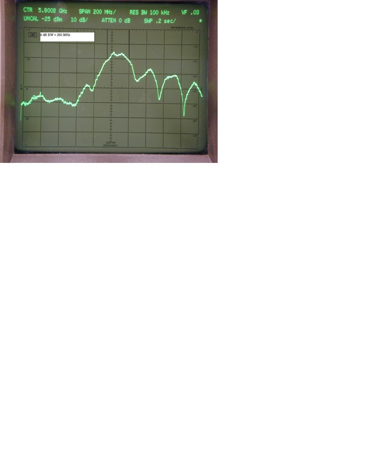
Lawrence Livermore National Laboratory Technical Description of 5.8 GHz RANGEFINDER by TEM Innovations Pleasanton, CA Lawrence Livermore National Laboratory P.O. Box 808, L-395 Livermore, CA 94551 August 1999 TEM Innovations Technical Note TN-001 TEM Innovations- 1 -925-484-0126 phone P.O. Box 10601925-484-0592 fax Pleasanton, CA [email protected] Modifying the LLNL Modular Rangefinder for Operation at 5.8GHz Introduction This note describes modifications to a standard LLNL (Lawrence Livermore National Lab) modular 6.4GHz pulse-echo radar rangefinder that was available from LLNL as a technology demonstration unit for licensing purposes. The unit described in this Note was built by and purchased from an LLNL licensee. It is but one of many configurations of a “Swiss Army Knife” modular system designed to demonstrate the flexibility and capabilities of the LLNL patent portfolio. Uses for the modular system include an electronic dipstick, an impulse radar imaging system, fluid level sensing using RF pulse- echo radar, and an electronic trip wire. The specifications for the configuration described herein are - 2 to 62-foot operational range (0.6 to 18.9-meters) - better than 0.1% of full scale timing accuracy over temperature - 1mm range resolution - FCC Part 15 compliance prescreening at 5.8GHz. Applications for this configuration include (1) liquid level measurement in storage tanks, (2) river and lake level sensing (environmental sensing), (3) industrial vat and process control, (4) range-gated beam interrupter systems, and countless other applications requiring high resolution radar. A detailed list of the modifications made for this configuration is available only to LLNL MIR licensees. Brief Description of the Modular Rangefinder The modular rangefinder is a sampling-type pulse-echo radar operating in the 5.8GHz band. It is comprised of universal modules that are part of a modular system developed at LLNL for demonstration purposes. Its operation can be understood with reference to the block diagram shown immediately below. A 1.25MHz pulse repetition frequency (PRF) clock drives a delay locked loop (DLL). The DLL splits the clock input into two outputs—a TX and an RX clock. These two clocks have a precise phase relation that is continuously swept by a voltage from the ramp generator. Typically, the TX-RX clock phase, or timing difference, is very linearly swept from 0 to 130ns every 100-milliseconds. Each negative edge of the 1.25MHz TX clock causes the TX module to transmit a short, 2ns-wide RF burst at 5.8GHz. Echo pulses arriving at the receiver module are gated and peak sampled by the receiver module with swept gate timing from the RX clock. The output of the receiver module is a sampled, expanded time replica of the received echoes. To compensate propagation losses, a variable gain amplifier (VGA) increases the receive path gain as the receive gate is increased in range. The signal from the VGA is rectified and smoothed (envelope detected) and applied to automatic threshold detectors. A digital pulse width modulated (PWM) output is produced by the detectors with a width that increases linearly and very accurately with target range. The PWM scale factor is typically 5-milliseconds per meter, so digitization of range is easily accomplished with a simple counter (not shown). TEM Innovations Technical Note TN-001 - 2 - RX clock 5.8GHz 1.25MHz PRF OSC ENVELOPE DETECTOR AND AUTOMATIC TX-RX PULSE DETECTORS PRECISION RAMP GENERATOR RECEIVER MODULE GATED PEAK-HOLD VGA DELAY LOCKED LOOP TRANSMIT MODULE PULSED OSC VIDEO OUT RANGE PWM OUT STC TIMING MODULE TX clock FIDU SAMPLING-TYPE PULSE-ECHO RANGEFINDER SIGNAL PROCESSOR MODULE The accuracy of the system is defined by timing scale factor errors, timing offset drift, timing nonlinearities such as digital crosstalk, and baseline clutter in the radar return. This note will show that scale factor errors and glitch errors are negligible at the 0.1% level, and that timing offset errors are controlled by the use of a timing reference or fiducial derived from the TX-RX main bang coupling. Errors due to clutter are a function of the radar scene and will not be addressed in this note. FCC considerations The rangefinder emits a very short RF pulse having a carrier frequency centered at 5800MHz and a bandwidth that is related to the inverse of the pulse width. While the FCC Part 15 regulations do not place a limit on minimum RF pulse width (there is a prohibition against carrier-free or impulse transmissions) the spectral characteristics of the pulse must comply with Part 15 regulations. Since the FCC employs a spectrum analyzer of limited bandwidth (~1MHz) compared to the RF emission width (~500MHz), a correction factor must be applied to yield a number indicative of the true RF carrier amplitude, which is what the FCC regulates. This correction factor is called the pulse desensitization correction factor (PDCF), PDCF = -20log(1.5BT), where B = analyzer bandwidth and T = RF pulse width. (see HP Application Note 150-2 for details) The PDCF (in decibels) is added to the observed RF carrier and its harmonics to get the true peak carrier and harmonic amplitudes. Sideband and spurious emissions are not TEM Innovations Technical Note TN-001 - 3 - subject to PDCF (according to an FCC communication). Several 5.8GHz pulsed-RF emitters have already been FCC Part 15 approved for LLNL MIR licensees (see FCC the website at www.fcc.gov). For the system described herein (with moderate gain antennas), its small GaAsFET transmit oscillator is barely capable of exceeding the peak carrier limit in the 5.8GHz ISM band, and it is generally incapable of exceeding permissible sideband levels in the adjacent 15.209 bands (the low power device or LPD bands). The challenge is (1) to reduce PD-corrected harmonic levels at 11.6GHz, 17.4GHz and higher and (2) to ensure there are no intentional emissions in the restricted bands, particularly at 5.4 and 7.2GHz. As will …
Text truncated - open the document above for the full version.
Operational Description
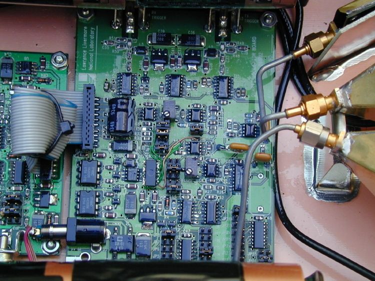
McEwan Technologies, LLC- 1 -925-484-0126 phone P.O. Box 10601925-484-0592 fax Pleasanton, CA [email protected] Technical Note Addendum Modifying the LLNL Rangefinder for Operation at 5.8GHz Transmitter component changes – Rev_B These changes replace Rev_A changes entirely 1. Change C3 to a 47 ohm 0805 resistor 2. Delete R2 3. Delete R4 4. Delete 5nH trace inductor in shunt with output, located at SMA 5. Shunt C6 with 1000pF 0805 chip cap with ground end soldered to SMA connector 6. Add 1.2cm wire to Q1 drain and dress along ground plane towards SMA and C6 and tune by adjusting height to ground plane for a null at 5.4GHz in output spectrum. 7. Cut trace between U1 pin 2 and pin 3, and connect a 22pF 0805 chip cap between pins 2,3. 8. Add a 200 ohm resistor from U1 pin 3 to ground (sets RF pulse width). 11/18/00 TEM Innovations- 1 -925-484-0126 phone P.O. Box 10601925-484-0592 fax Pleasanton, CA 94588-0601August 25, [email protected] Technical Note Addendum Modifying the LLNL Modular Rangefinder for Operation at 5.8GHz Detailed Component Changes Transmitter modifications C3=10pF Shunt C6 with 1000pF 0805 chip cap with ground end soldered to SMA connector C5 deleted, and replaced with 1.25cm long parallel wires (coupled-line resonators) R4 deleted Delete 5nH PCB trace inductor in shunt with output at SMA Add 1.1cm wire to ground and dressed in parallel to the coupled line resonators (5.4GHz trap) The resonators and trap should be tuned while monitoring the transmitted output on a spectrum analyzer. The resonator coupled to the GaAsFET drain fine-tunes the oscillator. All three wire resonators should be designed into the PCB as microstrips. A brass shield was soldered over the transmitter PCB. Receiver modifications C8=1.5pF C4=100pF Delete R6 and the trace inductor connected to the ground end of R6. Add a 4nH inductor between C6 and CR1 (input matching at 5.8GHz) Set switch S1 open CR1= HP HSMS 286F (lower cost) A brass shield was soldered over the receiver PCB. Timing module modifications C19=.022uF NPO ceramic (lower dielectric absorption than a film capacitor) C20,21= .01uF NPO ceramic R18=100K R15=10K R17=2.2M R37, 42, 45 = 470 R32=330K C26=1uF C27=.01uF C28=560pF C31=47pF Shunt C51 with 1000uF, 6V Al electrolytic Inadequate decoupling from on-board digital counters was creating excessive jitter at 60ft range. R20 trimpot, adjust for max - 2 - U10,11,19,20 = TS272 The original TLC2262 op amps were dropping out on the cold temperature end. It is not clear whether this is a batch dependent problem with these op amps or whether the problem shows up at longer delays. Tantalum thin film 8-resistor network (BI Technologies series 668A, available from Mouser at $3.10 each in unit quantities): R28=10K network R31=10K network R32=30K network (3 in series) R29=5K network (2 in parallel) One network resistor is left for making changes to R28,29,31,32 for scale factor changes, as desired. Signal processor modifications Select jumper JP1 for envelope detection Cut connection to U2 pin 6 (STC proportional to range) C43=.01uF C37=0.1uF C31, 32=0.2uF R57=10K R64=33K R65=15K Add .01uF in shunt with R55 (second order envelope detector filtering) U12=TS271 (original op amp, CLC401, is too drifty for slow risetime signals). Stretch reset pulse: R56=1meg Shunt R56 with a 220 ohm in series with a 1N4148 diode, anode facing U9A Connect .01uF from U9A pin 1 to gnd Antenna modifications Remove three damping resistors, and ensure that the feed section geometry is configured for 50 ohms. 96261711.sch-1 - Mon Mar 06 10:48:24 2000 96261771mod1.sch-1 - Mon Mar 06 10:47:06 2000
Operational Description
Lawrence Livermore National Laboratory Radar Rangefinder Demo Unit Model RF58-01 Rangefinder Radar Operation/Installation Instructions Description The RF58-01 rangefinder radar is a low-power, high-resolution, pulse-echo radar operating at 5.8 GHz. Its intended purpose is to very accurately measure relative changes in liquid level height. The unit is housed in plastic NEMA case, which is about 8-inches by 11-inches by 6-inches deep and uses 12VDC (batteries) for self-contained operation. Installation Proper operation of the RF58-01 rangefinder is dependent upon installation in a suitable environment and use of sound installation practices. This radar-based rangefinder must have an unobstructed view of the liquid surface to which ranging is required. Mounting and Location: Keep the front surface of the RF58-01 radar pointing at and parallel to the liquid surface. Mount the NEMA case 3ft away from the closest approach of the liquid surface. Use the following guidelines for selecting the best location to install the RF58-01: • DO NOT mount the radar within 2 feet of any metal objects. • DO NOT place any objects in front of the radar that may prevent a clear line of sight. Wiring Connections: The RF58-01 is battery operated with an ON-OFF switch next to the external connectors on the backside of the NEMA case. The VIDEO OUT connector is for trouble shooting the unit when connected to and appropriate oscilloscope. The RANGE PWM OUT is attached to an appropriate remote data- logger (user defined) for recording range. Specifications Input voltage 12VDC Typical current 200mA Maximum Range 60 feet Minimum Range 2 feet Operating Temperature -10F to +165F RF Frequency 5.8 GHz Range accuracy ±0.1% of Full Scale Range Resolution Less than 0.07 inches Output: Pulse Width Modulation (PWM) PWM scale factor in ms/ft Video Out 0 to +4 volts Packaging Standard NEMA case FCC Compliance This device complies with Part 15 of the FCC rules. Operation is subject to the following two conditions: 1. This device may not cause harmful interference 2. This device must accept any interference received, including interference that may cause undesired operation. FCC ID: xxx RF58-01 FCC Label Lawrence Livermore National Laboratory Model Number: RF58-01 FCCID: xxx RF58-01 This device complies with FCC Rules Part 15. Operation is subject to the following two conditions: (1) This device may not cause harmful interference and (2) This device must accept any interference that maybe received, including interference that may cause undesired operation. The FCC label is mounted on the outside back surface of the unit near the connectors and ON/OFF switch. Lawrence Livermore National Laboratory P.O. Box 808 Livermore, CA 94551 (925) 422-1100
Operational Description
Lawrence Livermore National Laboratory Technical Description of 5.8 GHz RANGEFINDER by TEM Innovations Pleasanton, CA Lawrence Livermore National Laboratory P.O. Box 808, L-395 Livermore, CA 94551 August 1999 TEM Innovations Technical Note TN-001 TEM Innovations- 1 -925-484-0126 phone P.O. Box 10601925-484-0592 fax Pleasanton, CA [email protected] Modifying the LLNL Modular Rangefinder for Operation at 5.8GHz Introduction This note describes modifications to a standard LLNL (Lawrence Livermore National Lab) modular 6.4GHz pulse-echo radar rangefinder that was available from LLNL as a technology demonstration unit for licensing purposes. The unit described in this Note was built by and purchased from an LLNL licensee. It is but one of many configurations of a “Swiss Army Knife” modular system designed to demonstrate the flexibility and capabilities of the LLNL patent portfolio. Uses for the modular system include an electronic dipstick, an impulse radar imaging system, fluid level sensing using RF pulse- echo radar, and an electronic trip wire. The specifications for the configuration described herein are - 2 to 62-foot operational range (0.6 to 18.9-meters) - better than 0.1% of full scale timing accuracy over temperature - 1mm range resolution - FCC Part 15 compliance prescreening at 5.8GHz. Applications for this configuration include (1) liquid level measurement in storage tanks, (2) river and lake level sensing (environmental sensing), (3) industrial vat and process control, (4) range-gated beam interrupter systems, and countless other applications requiring high resolution radar. A detailed list of the modifications made for this configuration is available only to LLNL MIR licensees. Brief Description of the Modular Rangefinder The modular rangefinder is a sampling-type pulse-echo radar operating in the 5.8GHz band. It is comprised of universal modules that are part of a modular system developed at LLNL for demonstration purposes. Its operation can be understood with reference to the block diagram shown immediately below. A 1.25MHz pulse repetition frequency (PRF) clock drives a delay locked loop (DLL). The DLL splits the clock input into two outputs—a TX and an RX clock. These two clocks have a precise phase relation that is continuously swept by a voltage from the ramp generator. Typically, the TX-RX clock phase, or timing difference, is very linearly swept from 0 to 130ns every 100-milliseconds. Each negative edge of the 1.25MHz TX clock causes the TX module to transmit a short, 2ns-wide RF burst at 5.8GHz. Echo pulses arriving at the receiver module are gated and peak sampled by the receiver module with swept gate timing from the RX clock. The output of the receiver module is a sampled, expanded time replica of the received echoes. To compensate propagation losses, a variable gain amplifier (VGA) increases the receive path gain as the receive gate is increased in range. The signal from the VGA is rectified and smoothed (envelope detected) and applied to automatic threshold detectors. A digital pulse width modulated (PWM) output is produced by the detectors with a width that increases linearly and very accurately with target range. The PWM scale factor is typically 5-milliseconds per meter, so digitization of range is easily accomplished with a simple counter (not shown). TEM Innovations Technical Note TN-001 - 2 - RX clock 5.8GHz 1.25MHz PRF OSC ENVELOPE DETECTOR AND AUTOMATIC TX-RX PULSE DETECTORS PRECISION RAMP GENERATOR RECEIVER MODULE GATED PEAK-HOLD VGA DELAY LOCKED LOOP TRANSMIT MODULE PULSED OSC VIDEO OUT RANGE PWM OUT STC TIMING MODULE TX clock FIDU SAMPLING-TYPE PULSE-ECHO RANGEFINDER SIGNAL PROCESSOR MODULE The accuracy of the system is defined by timing scale factor errors, timing offset drift, timing nonlinearities such as digital crosstalk, and baseline clutter in the radar return. This note will show that scale factor errors and glitch errors are negligible at the 0.1% level, and that timing offset errors are controlled by the use of a timing reference or fiducial derived from the TX-RX main bang coupling. Errors due to clutter are a function of the radar scene and will not be addressed in this note. FCC considerations The rangefinder emits a very short RF pulse having a carrier frequency centered at 5800MHz and a bandwidth that is related to the inverse of the pulse width. While the FCC Part 15 regulations do not place a limit on minimum RF pulse width (there is a prohibition against carrier-free or impulse transmissions) the spectral characteristics of the pulse must comply with Part 15 regulations. Since the FCC employs a spectrum analyzer of limited bandwidth (~1MHz) compared to the RF emission width (~500MHz), a correction factor must be applied to yield a number indicative of the true RF carrier amplitude, which is what the FCC regulates. This correction factor is called the pulse desensitization correction factor (PDCF), PDCF = -20log(1.5BT), where B = analyzer bandwidth and T = RF pulse width. (see HP Application Note 150-2 for details) The PDCF (in decibels) is added to the observed RF carrier and its harmonics to get the true peak carrier and harmonic amplitudes. Sideband and spurious emissions are not TEM Innovations Technical Note TN-001 - 3 - subject to PDCF (according to an FCC communication). Several 5.8GHz pulsed-RF emitters have already been FCC Part 15 approved for LLNL MIR licensees (see FCC the website at www.fcc.gov). For the system described herein (with moderate gain antennas), its small GaAsFET transmit oscillator is barely capable of exceeding the peak carrier limit in the 5.8GHz ISM band, and it is generally incapable of exceeding permissible sideband levels in the adjacent 15.209 bands (the low power device or LPD bands). The challenge is (1) to reduce PD-corrected harmonic levels at 11.6GHz, 17.4GHz and higher and (2) to ensure there are no intentional emissions in the restricted bands, particularly at 5.4 and 7.2GHz. As will …
Text truncated - open the document above for the full version.
Schematics
McEwan Technologies, LLC- 1 -925-484-0126 phone P.O. Box 10601925-484-0592 fax Pleasanton, CA [email protected] Technical Note Addendum Modifying the LLNL Rangefinder for Operation at 5.8GHz Transmitter component changes – Rev_B These changes replace Rev_A changes entirely 1. Change C3 to a 47 ohm 0805 resistor 2. Delete R2 3. Delete R4 4. Delete 5nH trace inductor in shunt with output, located at SMA 5. Shunt C6 with 1000pF 0805 chip cap with ground end soldered to SMA connector 6. Add 1.2cm wire to Q1 drain and dress along ground plane towards SMA and C6 and tune by adjusting height to ground plane for a null at 5.4GHz in output spectrum. 7. Cut trace between U1 pin 2 and pin 3, and connect a 22pF 0805 chip cap between pins 2,3. 8. Add a 200 ohm resistor from U1 pin 3 to ground (sets RF pulse width). 11/18/00 TEM Innovations- 1 -925-484-0126 phone P.O. Box 10601925-484-0592 fax Pleasanton, CA 94588-0601August 25, [email protected] Technical Note Addendum Modifying the LLNL Modular Rangefinder for Operation at 5.8GHz Detailed Component Changes Transmitter modifications C3=10pF Shunt C6 with 1000pF 0805 chip cap with ground end soldered to SMA connector C5 deleted, and replaced with 1.25cm long parallel wires (coupled-line resonators) R4 deleted Delete 5nH PCB trace inductor in shunt with output at SMA Add 1.1cm wire to ground and dressed in parallel to the coupled line resonators (5.4GHz trap) The resonators and trap should be tuned while monitoring the transmitted output on a spectrum analyzer. The resonator coupled to the GaAsFET drain fine-tunes the oscillator. All three wire resonators should be designed into the PCB as microstrips. A brass shield was soldered over the transmitter PCB. Receiver modifications C8=1.5pF C4=100pF Delete R6 and the trace inductor connected to the ground end of R6. Add a 4nH inductor between C6 and CR1 (input matching at 5.8GHz) Set switch S1 open CR1= HP HSMS 286F (lower cost) A brass shield was soldered over the receiver PCB. Timing module modifications C19=.022uF NPO ceramic (lower dielectric absorption than a film capacitor) C20,21= .01uF NPO ceramic R18=100K R15=10K R17=2.2M R37, 42, 45 = 470 R32=330K C26=1uF C27=.01uF C28=560pF C31=47pF Shunt C51 with 1000uF, 6V Al electrolytic Inadequate decoupling from on-board digital counters was creati…
Text truncated - open the document above for the full version.
Contact Information
Applicant
REXFORD MOREY [L-395](PROJECT ENGINEER)
Technical Contact
INTERNATIONAL TECHNOLOGY COMPANYBRUCE GORDON
[email protected]925-862-2944
9959 CALAVERAS ROAD · SUNOL, California · United States
Non-Technical Contact
INTERNATIONAL TECHNOLOGY COMPANYFUNKE ADERIBIGBE
[email protected]925-862-2944
Test Firm
ITC Engineering Services, Inc.Michael Gbadebo
Technical Specifications
| # | Rule Parts | Frequency Range | Power Output | Tolerance |
|---|---|---|---|---|
| 1 | 15C | 5.79 GHz - 5.82 GHz | - | ppm |