OXC457800AUTOMOTIVE KEY FOB
PFK Electronics (Pty) Limited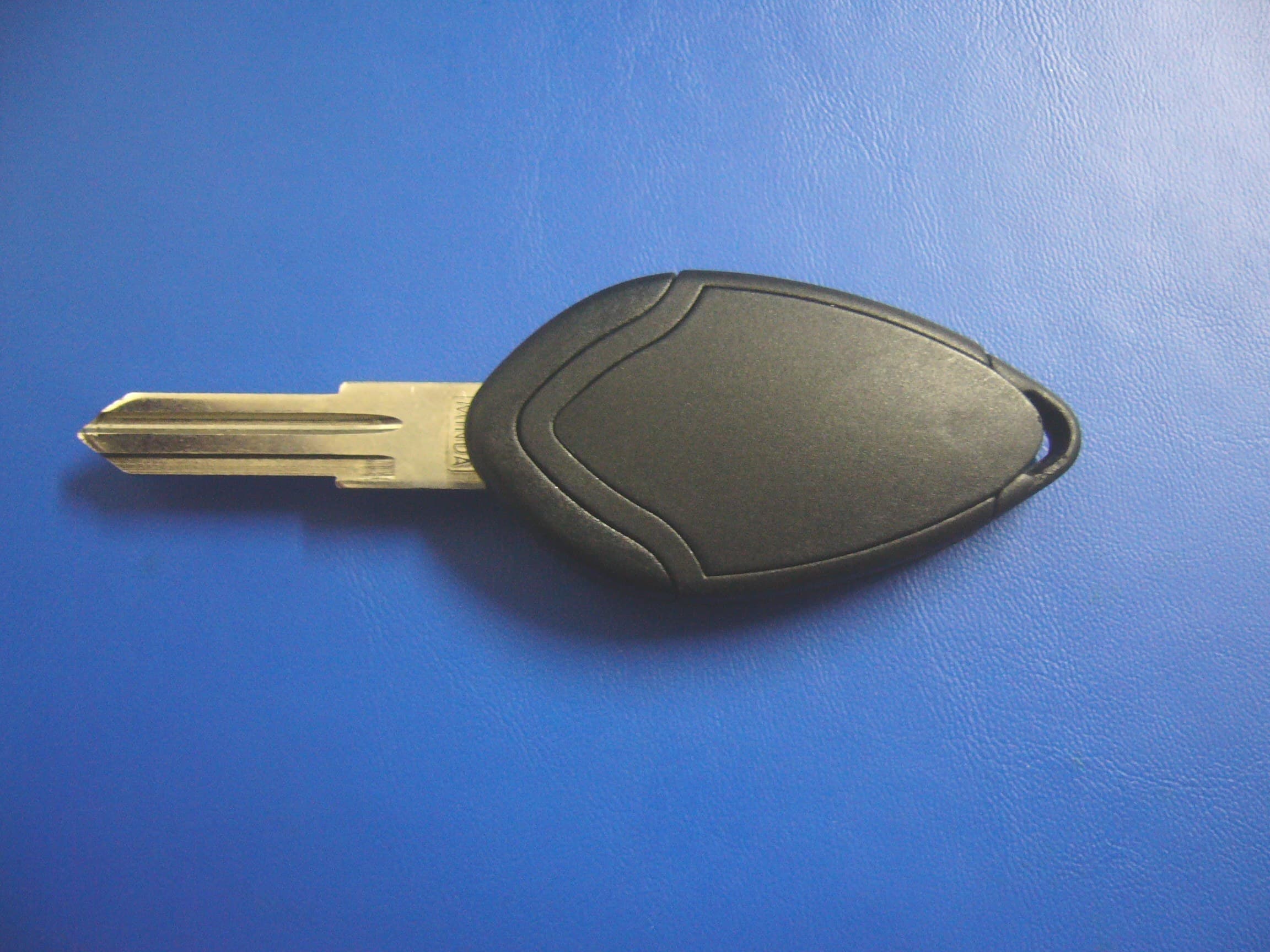
Click to zoom
Application Details
- Equipment Class
- DSC - Part 15 Security/Remote Control Transmitter
- Date of Grant
- Oct 09, 2007
- Application Purpose
- Original Equipment
- Date of Application
- Oct 09, 2007
- Equipment Note
- AUTOMOTIVE KEY FOB
- Frequency Range
- 433.52000000 - 434.52000000
- Country
- South Africa
Documents & Files
Document Text
Text extracted from the exhibit documents filed with the FCC. Open a document above to read the original.
Users Manual
intro18e and OWNER’S HANDBOOK 2008 M.Y. SUPPLEMENT To be read in conjunction with handbook D121T0324 LSL529 lsl529_oh_USA 08 supp.indd 128/09/2007 01:10:43 ‘08 M.Y. Supplement Vehicle Security Alarm The Lotus Elise/Exige for ‘08 model year onwards is fitted as standard with a PFK 457 immobiliser/alarm which includes the following features: • U.K. approval to Thatcham category 1. • ‘Dynamic coding’ of the transmitter keys; Each time the transmitters are used, the encrypted rolling code is changed to guard against unauthorised code capture. • Passive activation of immobiliser, central locking and alarm system. • Ingress protection using sensing switches on the latches of both doors, the front body access panels, and the engine lid/tailgate. • Selectable cockpit intrusion sensing using a microwave sen- sor. • Self powered siren to maintain protection if the vehicle battery is disconnected. • Personal protection by ‘on demand’ activation of the siren. • Emergency alarm override and transmitter key programming using an alarm/owner specific Personal Identification Number (PIN). Transmitter Keys Two transmitter keys are provided with the car, and combine a mechanical key blade with a three button transmitter unit incorpo - rated into the key head. The mechanical key operates the ignition switch, emergency manual door locks and Elise engine/boot lid. Manual siren, aux. Disarm, mobilise, u nlock Arm & Lock TRANSMITTER KEY ohs128c 2 lsl529_oh_USA 08 supp.indd 228/09/2007 01:10:44 ‘08 M.Y. Supplement The transmitter operates the electronic immobiliser, alarm system and the central locking. The two transmitter keys should be kept separate, and a replacement obtained immediately after any loss to ensure that a spare is always available. The 4-digit code for the mechanical key, the unique serial number of the immobiliser/alarm, and the vehicle owner’s 5-digit alarm Personal Identification Number (PIN), are supplied on plastic tags attached to the key ring of a new vehicle. In order to allow replacement transmitter keys to be ordered, it is essential that these numbers are recorded and kept safely with the vehicle documents. If the codes are not available on receipt of the car, enquire with the dealer immediately. Disarming the Alarm/Unlocking When approaching the car, it is likely that the vehicle is locked and the alarm armed. The alarm red tell tale lamp in the speedometer face will be triple flashing. To disarm the alarm and unlock the doors: - Press the central, unlock, button on the transmitter key. The first press will unlock just the driver’s door. Two presses in quick succession will unlock both the driver and passenger doors. - This command will be acknowledged by a double flash of the hazard lamps. - The engine will be mobilised (see below). - The interior lamp will fade on, and remain lit for up to 2 minutes (if set to the ‘courtesy’ position). - The alarm tell tale will be extinguished. If a door is not opened within 2 minutes, the doors will pas - sively re-lock and the alarm system re-arm. Passive Immobilisation In order to provide a measure of automatic vehicle security, independent of any driver initiative, the system will ‘passively’ immobilise the engine’s cranking and fuel pump circuits after the ignition has been turned off for 40 seconds, or a similar period has elapsed since the last mobilising command. With the ignition off, the alarm tell tale will indicate that immobilisation is in effect by briefly flashing every second. With ignition on, immobilisation is indicated by a continuously lit tell tale. 3 lsl529_oh_USA 08 supp.indd 328/09/2007 01:10:44 ‘08 M.Y. Supplement To mobilise the car (i.e. allow engine starting) with ignition on or off, press once the transmitter centre button; the alarm tell tale will be extinguished. Arming the Alarm/Locking the Doors To lock the doors and arm the alarm, remove the ignition key, close both doors, and check that the engine lid/tailgate and body front access panels are secure: - Press once the raised logo button on the transmitter fob. - This command will be acknowledged by a single flash of the hazard lamps. - Both doors will be locked, the engine immobilised and the alarm system armed. A settling period of 40 seconds must expire before the ingress sensors become active. - The alarm tell tale will repeatedly triple flash. Note: i) If the system is armed when a door is not fully shut, three triple beeps will sound as a warning and the doors will not be locked. Opening a door will not trigger the alarm. ii) If the system is armed when the engine lid/tailgate or a front access panel is not fully closed, three warning double beeps will be heard, and the doors will not be locked. Opening a door in this instance will trigger the alarm. iii) If one transmitter is used to disarm the alarm, and a second transmitter to re-arm, a system test mode will be initiated, and operational variations will occur. Allow an undisturbed period of 2 minutes to elapse to restore normal operation. When fully armed, and after the settling period of 40 seconds has expired, the alarm will be triggered by any of the following actions: - Interruption of the car battery power supply or siren cables. - Energising the ignition circuit (‘hot wiring’). - Opening a door; - Opening the engine lid/tailgate or a front access panel. - Movement detected within the cabin (unless de-selected). If the alarm is triggered, the hazard warning lamps will flash and the wailing siren will sound for a period of approximately 30 seconds before closing down and resetting, ready for any further triggering input. If a trigger is continuously present (e.g. door left 4 lsl529_oh_USA 08 supp.indd 428/09/2007 01:10:44 ‘08 M.Y. Supplement open), the alarm will repeat for a maximum of eight 30 second cycles before excluding the triggering sensor for the remainder of the armed period. To silence the siren, press once the central, disarm button on the transmitter key. If necessary, press a second time …
Text truncated - open the document above for the full version.
Block Diagram
457 800 Key Fob Transmitter Block Diagram Modulation ± ±± ±1.8 KHz HCS 300 ENCODER COLPITTS OSCILLATOR Frequency set by SAW1 SAW1 SAW RESONATOR 433.92MHz ± ±± ±150KHz
ID Label/Location Info
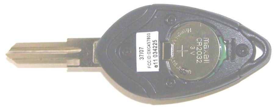
457 800 Key Fob Label Location Justification The position chosen for the FCC label is on the main part of the unit under the battery cover. The reasons for this choice are as follows: The battery cover is easily removable by unclipping the cover from the main unit. No special tools are required for screws or any additional fastening devices. The only space available on the outside on the unit is on the removable battery cover. In the event of the cover being left off or lost the FCC qualification would not be evident. For practical and aesthetic reasons the label could not be placed on the front or sides of unit because of limited space and the position of the press buttons. In the position chosen, the FCC Label will be easily seen when the battery cover is removed. The label is positioned such that it can be seen without removing the battery. The Key Fobs are normally supplied with batteries to the new owner when the vehicle for which it is intended is purchased. In the event of a spare or replacement Key Fob being purchased it would be necessary to fit the battery at the time of purchase and the FCC label would then be seen. E. A. B. Ulett Project Coordinator
Operational Description
457 800 TRANSMITTER OVERVEIW . The product is a low power transmitter used to control the vehicle alarm and convenience features. CIRCUIT DESCRIPTION . Power is derived from a single CR2932 Lithium cell. IC 1 is an encoder. It is programmed with the Keeloq algorithm and unique manufacturer’s key. When a switch is pressed the IC outputs the next code in the sequence together with the switch information to pin 6. Tr1 and associated components form a Colpitts oscillator. SAW1 sets the frequency. L1 is an inductor etched onto the PC Board. It is the DC path for the oscillator and also acts as the radiating element. C2 and C3 provide feedback and are resonant with L1. R3 prevents parasitic oscillations. The PWM output from pin 6 of IC1 provides the base bias for the oscillator. The oscillation is turned on and off by this signal. C1 is a de-coupling capacitor. The ground plane on the PC board and the battery provide the ground reference for the radiating element.
Parts List/Tune Up Info
PARTS LIST REV : 1 9/12/2007 FOR PRODUCTION USE : PFK Electronics (Pty) Ltd. COMPILED BY: PAGE NO. 1 Of 2 JOB INSTRUCTION JOB INST. NO. PD PD05/01/02 APPROVED BY: CONTROLLED COPY NO. EFFECTIVE DATE 457800 – AUTO REMOTE LOTUS KEYFOB AUTO REMOTE LOTUS KEYFOB – 457800 SUB ASSY : 457810 COMPONENTS : QTY PFK PART NO. PFK DESCRIPTION NPG. 1 PL457/400 REMOTE KEY TOP COVER 3672 1 PL457/500 REMOTE KEY BOTTOM 3673 1 PL457/550 REMOTE KEY BATTERY COVER 3674 1 PL457/700 REMOTE MEMBRANE – 3 BTN 3675 1 PL457/600 REMOTE DOME BADGE “LOTUS” 3676 3 HS/S/TAP/19 SCREW S/T C/SUNK 2.2*7 PT 1 HS/S/TAP/26 SCREW S/T 2*6MM C/S POZI HD 1 BAT3VC2032/00 BATTERY LITHIUM 3V CR2032 0.5 GC/BEADTIE/00 BEAD TIE CLEAR 125MM 0.5 PL056/140 CODE TAG PLASTIC 3-BTN KEYFOB XMITTER PCB ASSY – 457810 SUB ASSY : 457811 COMPONENTS : REF. PFK PART NO. PFK DESCRIPTION NPG. T1 BAT/TERM/04 BATTERY TERMINAL (VERTICAL) 3677 T2 BAT/TERM/05 BATTERY TERMINAL (HORIZONTAL) 3678 PARTS LIST REV : 1 9/12/2007 FOR PRODUCTION USE : PFK Electronics (Pty) Ltd. COMPILED BY: PAGE NO. 2 Of 2 JOB INSTRUCTION JOB INST. NO. PD PD05/01/02 APPROVED BY: CONTROLLED COPY NO. EFFECTIVE DATE 3-BTN KEYFOB XMITTER SMD ASSY - 457811 REF. PFK PART NO. PFK DESCRIPTION NPG. TR1 2STBFS17/00 TRANSISTOR BFS17 SMD IC1 2SIDHCS300/00 IC KEELOQ HCS-300 C1 2C0470NA/02 CAP 470P 0603 NPO 50V NiSn C2 2CB390NA/02 CAP 3P9 0603 NPO 50V NISN C3 2CA120NA/02 CAP 12P 0603 NPO 50V NiSn C4 ----------------- NOT USED C5 ----------------- NOT USED R1 2RC2100/02 RES CHIP 10K 0603 NiSn 1% R2 2RC0150/02 RES CHIP 150R 0603 NISN 1% R3 2RCA120/02 RES CHIP 12R 0603 NISN 5% R4 2RCB000/02 RES CHIP 0R 0603 NISN 5% SAW1 2XSAW433M/01 SAW RESONATOR 433.92MHz SMD VSR433053 SW1 2EMSW/TACT/02 SWITCH TACTYL ITT Y35A25120FP SW2 2EMSW/TACT/02 SWITCH TACTYL ITT Y35A25120FP SW3 2EMSW/TACT/02 SWITCH TACTYL ITT Y35A25120FP 1 PCB457/812/01 PCB 3-BTN TX PFK457-812 R.1 3679
Test Report
Page 1 of 15 No. 1116 Electromagnetic Compatibility Test of: Automotive Keyfob Transmitter Model Number: 457800 Applicant: PFK Electronics (PTY) Ltd. Test Type: Compliance Test Specification: FCC CFR 47, part 15.231: 2006 SGS Serial Number: EMC110493/1/CL/07 Date of Receipt: 4 th July 2007 Date of Test(s): 4 th July 2007 to 10 th July 2007 Date of Issue: 25 th September 2007 Issue Number: 2 This report is issued by the Company subject to its General Conditions of Service available upon request and accessible at www.sgs.com. Attention is drawn to the limitations of liability, indemnification, jurisdictional, representative restrictions of test samples and sample retention policies defined therein. This report refers only to the sample submitted for test. This report shall not be reproduced except in full without the written approval of the testing laboratory. Any compliance statements in this report are made reliant on the modes of operation and the failure criteria as instructed to us by the Customer based on their specific knowledge of the application and functionality of the EUT. Authorised Signatory A. Reynard Technical Manager TEST REPORT Page 2 of 15 Issue Date:25 th September 2007 SGS Serial Number:EMC110493/1/CL/07 Issue Number: 1 CONTENTS Page Number 1. Client Information...........................................................................................................................3 2. Details Of Test Laboratory.............................................................................................................3 3. Equipment Under Test (EUT) ........................................................................................................4 3.1 Identification Of EUT...................................................................................................................................................... 4 3.2 Overview 4 3.3 Circuit Description.......................................................................................................................................................... 4 4. Test Specification, Methods and Procedures .............................................................................5 4.1 Test Specification(s) ...................................................................................................................................................... 5 4.2 Purpose Of Test............................................................................................................................................................. 5 4.3 Methods and Procedures................................................................................................................................................ 6 5. Deviations or Exclusions from the Test Specifications.............................................................7 6. Operation of the EUT During Testing / Configuration and Peripherals....................................8 6.1 Operation of EUT during testing. ................................................................................................................................... 8 6.2 Configuration and Peripherals ........................................................................................................................................ 8 7. Test Results ....................................................................................................................................8 7.1 General Comments........................................................................................................................................................ 8 7.2 Modifications Made to the EUT...................................................................................................................................... 8 7.3 Summary of Test Results ............................................................................................................................................... 9 7.4 Radiated Emissions Test Results 15.231 ............................................................................. 10 7.5 Range of Modulation Bandwidth 15.231............................................................................... 14 TEST REPORT Page 3 of 15 Issue Date:25 th September 2007 SGS Serial Number:EMC110493/1/CL/07 Issue Number: 1 1. Client Information Company Name: PFK Electronics (PTY) Ltd. Address: 488 Umbilo Road Durban Kwa Zulu Natal PO Box 3660 South Africa Contact Person: Hugh Thibaud Telephone: 27 31 274 7200 Facsimile: 27 31 205 4324 2. Details Of Test Laboratory Company Name: SGS UK Ltd. UKAS Accreditation Number: 1116 Address: South Industrial Estate, Bowburn, Co. Durham, DH6 5AD. Contact Persons: Mr Alan Reynard Telephone: +44 191 377 2000 Facsimile: +44 191 377 2020 TEST REPORT Page 4 of 15 Issue Date:25 th September 2007 SGS Serial Number:EMC110493/1/CL/07 Issue Number: 1 3. Equipment Under Test (EUT) 3.1 Identification Of EUT Model Number: 457800 Unique Identifier: Not Supplied Description of EUT: Automotive Keyfob Transmitter Highest Internal Clock Frequencies: 433MHz Supply Voltage: 3V DC Battery Ports present: Enclosure Accessories Supplied: None 3.2 Overview The product is a low power transmitter used to control the vehicle alarm and convenience features. 3.3 Circuit Description Power is derived from a single CR2932 Lithium cell. IC 1 is an encoder. It is programmed with the Keeloq algorithm and unique manufacturer’s key. When a switch is pressed the IC outputs the next code in the sequence together with the switch information to pin 6. Tr1 and associated components form a Colpitts oscillator. SAW1 sets the frequency. L1 is an inductor etched onto the PC Board. It is the DC path for the oscillator and also acts as the radiating element. C2 and C3 provide feedback and are resonant with L1. R3 prevents parasitic oscillations. The PWM output from pin 6 of IC1 provides the base bias for the oscillator. The oscillation is turned on and off by this signal. C1 …
Text truncated - open the document above for the full version.
Contact Information
Applicant
Alan Sullivan(Chief Technical Officer)
Test Firm
SGS United Kingdom Ltd.Andrew Nicholson
Technical Specifications
| # | Rule Parts | Frequency Range | Power Output |
|---|---|---|---|
| 1 | 15.231 | 433.52 MHz - 434.52 MHz | - |
Other Applications from PFK Electronics (Pty) Limited
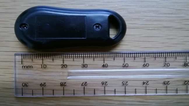
OXC844300
Jul 24, 2014Car Dealer Remote Key
Equipment Class
DSC - Part 15 Security/Remote Control Transmitter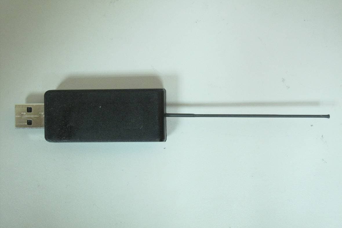
OXC720600
Jan 17, 2013720/740 RF Dongle
Equipment Class
DTS - Digital Transmission System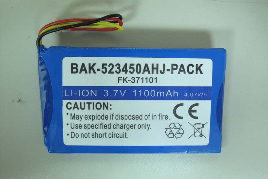
OXC740000
Jan 17, 2013740 WAB
Equipment Class
DTS - Digital Transmission System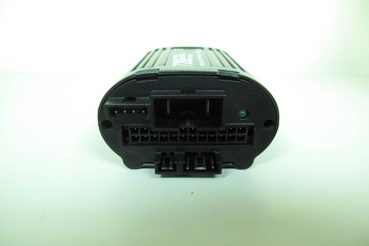
OXC720100
Jan 16, 2013720/740 VBS
Equipment Class
DTS - Digital Transmission System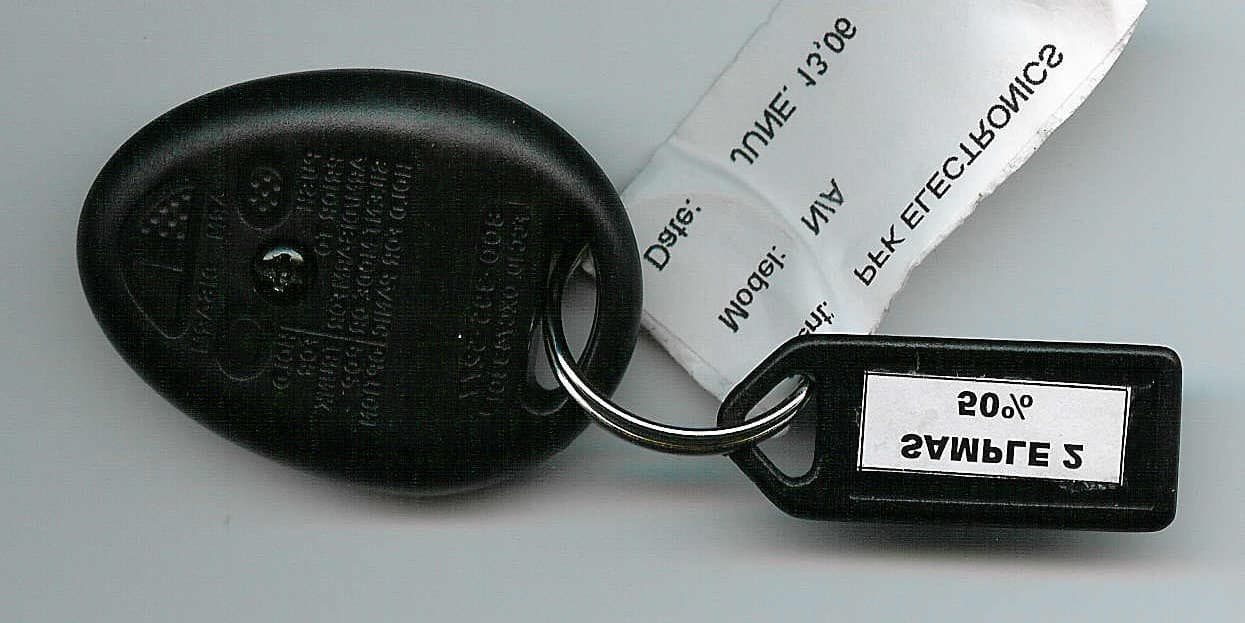
OXC743301
Sep 11, 2006LOW POWER TRANSMITTER
Equipment Class
DSC - Part 15 Security/Remote Control Transmitter