FCCID.CO- FCC ID Database
HomeCompaniesEquipment ClassesSearch

© 2026 FCC ID Database. All rights reserved.

AboutContactData sourced from FCC public records
  1. Home/
  2. GPS Industries Inc./
  3. OXKBSI2000

OXKBSI2000Single Channel 2.4 GHz Direct Sequence Spread Spec

GPS Industries Inc.
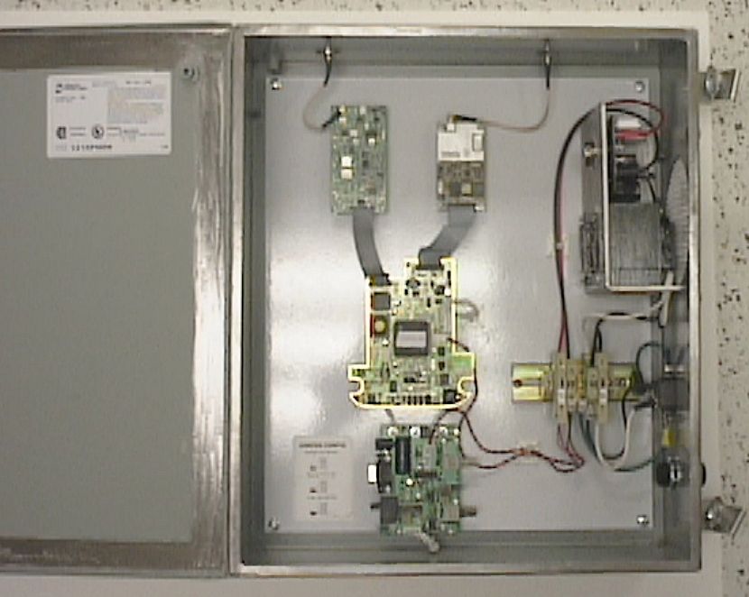
Single Channel 2.4 GHz Direct Sequence Spread Spec - FCC ID OXKBSI2000 - GPS Industries Inc.
Click to zoom

Application Details

Equipment Class
DSS - Part 15 Spread Spectrum Transmitter
Date of Grant
Apr 09, 2000
Application Purpose
Original Equipment
Date of Application
Mar 15, 2000
Equipment Note
Single Channel 2.4 GHz Direct Sequence Spread Spec
Frequency Range
2456.00000000 - 2456.00000000
Company
GPS Industries Inc.
Country
Canada

Documents & Files

Select a file to view

Users Manual

↗
↗

Cover Letter(s)

↗

External Photos

↗
↗
↗
↗
↗
↗

ID Label/Location Info

↗
↗

Internal Photos

↗
↗
↗

Operational Description

↗

Test Report

↗
↗
↗
↗

Document Text

Text extracted from the exhibit documents filed with the FCC. Open a document above to read the original.

Users Manual

Suite 214, 5500 - 152 nd Street, Surrey, B.C. Canada V3S 8E7 Telephone 604-576-7442 Fax 604-576-7460 1-888-594-FORE (3673) E-mail: [email protected] ! Website: www.inforetech.com D:\Ready_To_Convert\Doc\91736.DOC 4 th February, 2000 Federal Communications Commission 7435 Oakland Mills Road COLUMBIA MD 21046 To Whom It May Concern This is to state that the user manual literature for the BSI 2000 and inFOREmer 2000 are not available for submittal with our other product documentation at this time. However, we will be creating these documents and will include appropriate Industry Canada and FCC Statements prior to the product release, at which time we will forward them to the FCC. Regards, Gary Zywiecki Director of Engineering

Users Manual

Clubhouse ComputerAppendix B CHC User's Manual - Rev B 10-1  2000, Inforetech Golf Technology 2000 Inc. Appendix B – Sepecifications and Regulatory Information Specifications The Inforetech system uses two computers: • The Linux computer that communicates with the base station, handsets, and charging station. • The Windows NT computer (acting as a server) is networked to the Linux computer, and provides the user interface to the Linux system. One (or more) computers can act as clients to the NT server to provide access to the system from other offices at the golf course. Linux Computer Specifications The following table shows the specifications for the Linux Computer. ProcessorIntel Celeron 400 MHz RAM32 MB Hard Disk Drive4 GB CD-ROM20X Video Card4 MB Network CardNE2000 compatible Communications Card RS-485 PCI card. Model OMG-ULTRA-485 Operating SystemDebian Linux 2.1 Clubhouse ComputerAppendix B CHC User's Manual - Rev B 10-2  2000, Inforetech Golf Technology 2000 Inc. Club House Computer Specifications The following table shows the specifications for the Clubhouse Computer. ProcessorIntel Pentium II 266 MHz (455 MHz preferred) RAM256 MB L1 cache23 KB L2 cache512 KB MotherboardPCI and ISA Hard Disk Drive4 GB or larger CD-ROM20X Video Card4 MB Serial PortsTwo, 16650 compatible ParallelOne, bidrectional USB portsTwo Video CardATI 3D Rage Pro AGP 2x with 4 MB or 8 MB Modem56.6 kbps Monitor19", 1600 x 1200 pixels, 256 colors Network CardNE2000 compatible Audio CardSound Blaster 16-bit compatible Communications Card RS-485 PCI card. Model OMG-ULTRA-485 Operating System Microsoft Windows NT 4.0 Workstation PrinterColor Printer with parallel connection. Keyboard101-keys Mouse3-button Remote Presentation Computer Specifications Same specifications as Clubhouse Computer, except without RS-485 card. Clubhouse ComputerAppendix B CHC User's Manual - Rev B 10-3  2000, Inforetech Golf Technology 2000 Inc. Regulatory Information FCC Registration The InFOREmer 2000 Handsets and Base Station have been tested and comply with the limits for a Class A digital device, pursuant to Part 15 of the FCC Rules. These limits are designed to provide reasonable protection against harmful interference when equipment is operated in a commercial environment. This equipment generates, uses, and can radiate radio frequency energy and, if not installed and used in accordance with the instruction manual, may cause harmful interference to radio communications. Operation of this equipment in a residential area is likely to cause harmful interference in which case the user will be required to correct the interference at his own expense. Caution: Any changes or modifications to the handsets or base station, not expressly approved by Inforetech Golf 2000 Inc. could void the user's authority to operate the equipment. Industry Canada Regulations With respect to the InFOREmer Handsets and Base Station, this Class A digital apparatus meets all requirements of the Canadian Interference- Causing Equipment Regulations. Cet appareil numérique de la classe A respecte toutes les exigences du Règlement sur le matériel brouilleur du Canada. Handset Compliance and Labeling The following is a statement of compliance for the handset: Inforetech Golf Technology 2000 Inc. FCCD: OXKINFORMER2000 ISC:XXX XXX XXXX This device complies with Part15 of the FCC Rules. Operation is subject to the following two conditions: (1) This device may not cause harmful interference, and (2) this device must accept any interference received, including interference that may cause undesired operation. Clubhouse ComputerAppendix B CHC User's Manual - Rev B 10-4  2000, Inforetech Golf Technology 2000 Inc. The following is an example of the label attached to the handset: Inforetech Golf Technology 2000 Inc. FCCD: OXKINFORMER2000 ISC:XXX XXX XXXX Base Station Compliance and Labeling FCC and IS Labels The following is an example of the label attached to the Base Station: Inforetech Golf Technology 2000 Inc. FCCD: OXKBSI200 ISC:XXX XXX XXXX This device complies with Part15 of the FCC Rules. Operation is subject to the following two conditions: (1) This device may not cause harmful interference, and (2) this device must accept any interference received, including interference that may cause undesired operation.

Cover Letter(s)

Suite 214, 5500 - 152 nd Street, Surrey, B.C. Canada V3S 8E7 Telephone 604-576-7442 Fax 604-576-7460 1-888-594-FORE (3673) E-mail: [email protected] ! Website: www.inforetech.com D:\Ready_To_Convert\Doc\91738.DOC 4 th February, 2000 Federal Communications Commission 7435 Oakland Mills Road COLUMBIA MD 21046 To Whom It May Concern This is to request that all schematics associated with the BSI 2000 and inFOREmer 2000 remain confidential. These products are pioneering a new application of GPS in the market place, and as we near product release, we feel that confidentiality is required in order to protect our market position at this sensitive time. Regards, Gary Zywiecki Director of Engineering

Operational Description

This document contains proprietary information belonging to InFOREtech Golf Technology 2000 Inc., and its possession does not convey any rights to reproduce, disclose its contents, or to manufacture, use or sell anything it may describe. Reproduction, or use without the specific written authorization of InFOREtech Golf Technology 2000 Inc. is strictly forbidden. Intergrated Project PlanRev. 1.01 1. Product Assessment 1.1 TECHNICAL ASSESSMENT: 1.1.1 Te chnical De scription The inFOREmer 2000 is a comprehensive data network having the ability to collect data from the global positioning satellites (GPS) and transfer data between a central computer and a variety of peripherals including base station, repeater, mobile handsets and charging cradles. The method of data communication is unique to the inFOREmer 2000 system and is achieved through a combination of w ireless radio and infra red (IR) technologies, as well as hard wired phone and fiber optic cables all managed by internet protocols. Wireless radio is used to communicate w ith the handsets w hile in operation on the golf course; IR links fiber optic cabling and a dedicated internet connection is used to communicate with the handsets while being recharged on the charging cradles. Transmission Control Protocol/Internet Protocol (TCP/IP) is the communication protocol used by the pace- of-play system to ensure reliability and maximum system availability. TCP/IP provides virtually unlimited expandability and unparalleled reliability and flexibility to meet future technological enhancements thereby offering a continually advanced, unique and competitive pace-of-play system. The TCP/IP protocol facilitates remote updating of Clubhouse Computer and handset software via the internet. Every inFOREmer 2000 system in operation will be updated with the latest software version in a transparent and trouble free manner for the golf course management and users. Each golf course will have a custom version of the proprietary software with maps and information relating to that specific golf course. The maps are created from digitized, image enhanced aerial photographs. The core technical features of the system are the ability to communicate with all the handsets in the field on a regular basis, and provide an accurate positioning reading at the handset that allows the golfer to read distances on the golf course to an accuracy of +/- 3 feet. This is done through the use of a GPS device w ithin the handset, w orking in unison w ith a radio link that provides error correction information from the clubhouse computer. This technology is know n as Differential GPS (“DGPS”). The core technical features of the system are the ability to communicate with all the handsets in the field on a regular basis, and provide an accurate positioning reading at the handset that allows the golfer to gauge distances on the golf course to an accuracy of +/- 1m. This is done through the use of a GPS device w ithin the handset, w orking in unison w ith a radio link that provides error correction information from the clubhouse. This is a technology know n as Differential GPS (D-GPS). The system is explained below. 1.1.2 System Components • Club House Computer The Club House Computer is the central hub, and is responsible for managing the communications process for the netw ork. It controls the routing information for w hich all the other units respond to or communicate with. It displays the User graphics at the clubhouse to allow the operator to monitor all aspects of the system, and more importantly, the golfers using the system. This document contains proprietary information belonging to InFOREtech Golf Technology 2000 Inc., and its possession does not convey any rights to reproduce, disclose its contents, or to manufacture, use or sell anything it may describe. Reproduction, or use without the specific written authorization of InFOREtech Golf Technology 2000 Inc. is strictly forbidden. Intergrated Project PlanRev. 1.02 • Base Station Interface The Base Station Interface Unit is a router that provides the communication link for the GPS and the Radios within the handsets. It is typically stored on or near the roof of the clubhouse, in close proximity to the RF and GPS antennas that are connected to it. • Handsets The handsets are the mobiles units in the system that provide the individual golfers with the information they require. The handsets are composed of a CPU, viewscreen, GPS receiver, radio and batteries which allows for twelve (12) hours of operation without re-charging. The system is designed to handle up to 150 handsets on the golf course typically. • Charging Station The charging station provides the means by which the handsets are charged, and also are communicated to for status monitoring, and new s/w updates. This is done through an IRDA link w hile each handset sits in it’s separate charging cradle. • Repeater The Repeater is used to provide Radio extension on the golf course where the main Base Station would otherwise not provide coverage. Not all courses will require a Repeater. The repeater is discussed in more detail in it’s own separate Functional Specification. • Network Monitoring Centre The system has been designed such that each product within the system is IP addressable. This allows for a very flexible Network Monitoring Capability to be included that provides the means to ensure the system is operating without problems, and to quickly service any problems that may occur. The Network Monitoring Centre will be able to access any system in the world, and either manage, monitor, or provide updated software to the units remotely. This will be done either through the Internet, or through a dedicated dial up line.

Test Report

Valh all a Sy st ems Inc. 1999 Paul Slavens Chief EMC Engineer ACME TESTING Dear Paul, Please find attached the inFOREmer 2000 product images you requested (product & circuit boards – both sides) in jpeg format, as well as the results of the Jamming margin / processing gain tests. The processing gain was measured to be 11 dB using the Carrier Peak Power measurement, and 13 dB using the Carrier Avg. Power jamming margin measurement, both exceeding the 10 dB requirement. I’ve included a copy of the FCC Public Notice 54797 “GUIDANCE ON MEASUREMENTS FOR DIRECT SEQUENCE SPREAD SPECTRUM SYSTEMS”, used to do the measurement, as well as the test results, and the jamming margin application notes from the IC supplier (Harris Semiconductor). V ALHALLA S YSTEMS RF ENGINEERING 399A Mountain Highway North Vancouver, B.C. Canada V7J 2K9 Phone: (604) 904-6515 Fax: (604) 904-6516 Valhalla Systems Inc Valh all a Sy st ems Inc. 1999 PUBLIC NOTICE Federal Communications Commission 1919 M Street NW Washington, DC 20554 54797 News media information 202/418-0500 Recorded listing of releases and texts 202/418-2222 July 12, 1995 GUIDANCE ON MEASUREMENTS FOR DIRECT SEQUENCE SPREAD SPECTRUM SYSTEMS Part 15 of the FCC Rules provides for operation of direct sequence spread spectrum transmitters. Examples of devices that operate under these rules include radio local area networks, cordless telephones, wireless cash registers, and wireless inventory tracking systems. The Commission frequency receives requests for guidance as to how to perform measurements to demonstrate compliance with the technical standards for such systems. No formal measurement procedure has been established for determining compliance with the technical standards. Such tests are to be performed following the general guidance in Section 15.31 of the FCC Rules using good engineering practice. The following provides information on the measurement techniques the commission has accepted in the past for equipment authorization purposes. Alternative techniques may be acceptable upon the consultation and approval by the Commission staff. The information is organized according to the pertinent FCC rule sections. Section 15.31(m): This rule specifies the number of operating frequencies to be examined for tunable equipment. Section 15.207: Power line conducted emissions. If the unit is AC powered, an AC power line conducted test is also required per this rule. Section 15.247(a)(2): Bandwidth. Make the measurement with the spectrum analyzer's resolution bandwidth (RBW) = 100 kHz. In order to make an accurate measurement, set the span >> RBW. Section 15.247(b): Power output. This is an RF conducted test. Use a direct connection between the antenna port of the transmitter and the spectrum analyzer, through suitable attenuation. Set the RBW > 6 dB bandwidth of the emission or use a peak power meter. Section 15.247(c): Spurious emissions. The following tests are required: 1. RF antenna conducted test: Set RBW = 100 kHz, Video bandwidth (VBW) > RBW, scan up through 10th harmonic. All harmonics/spurs must be at least 20 dB dow n from the highest emission level within the authorized band as measured with a 100 kHz RBW. 2. Radiated emission test: Applies to harmonics/spurs that fall in the restricted bands listed in Section 15.205. The maximum permitted average field strength is listed in Section 15.209. A pre-amp (and possibly a high-pass filter) is necessary for this measurement. For measurements above 1 GHz, set RBW = 1 MHz, VBW = 10 Hz, Sweep: Auto. If the emission is pulsed, modify the unit for continuous operation, use the settings show n above, then correct the reading by subtracting the peak-average correction factor derived from the appropriate duty cycle calculation. See Section 15.35(b) and (c). Section 15.247(d): Power spectral density. Locate and zoom in on emission peak(s) within the passband. Set RBW = 3 kHz, VBW > RBW, sweep = (Span / 3 kHz) e.g., for a span of 1.5 MHz, the sweep should be 1.5 x 10 6 / 3 x 10 3 = 500 seconds. The peak level measured must be no greater than +8 dBm. If external attenuation is used, don't forget to add this value to the reading. Use the following guidelines for modifying the power spectral density measurement procedure when necessary. • For devices with spectrum line spacing greater than 3 kHz no change is required. • For devices with spectrum line spacing equal to or less than 3 kHz, the resolution bandwidth must be reduced below 3 kHz until the individual lines in the spectrum are resolved. The measurement data must then be normalized to 3 kHz by summing the power of all the individual spectral lines within a 3 kHz band (in linear power units) to determine compliance. • If the spectrum line spacing cannot be resolved on the available spectrum analyzer, the noise density function on most modern conventional spectrum analyzers will directly measure the noise power density normalized to a 1 Hz noise power bandwidth. Add 30 dB for correction to 3 kHz. • Should all the above fail or any controversy develop regarding accuracy of measurement the Laboratory will use the HP 89440A Vector Signal Analyzer for final measurement unless a clear showing can be made for a further alternate. Valh all a Sy st ems Inc. 1999 Section 15.247(e): Processing Gain. The Processing Gain may be measured using the CW jamming margin me t ho d. Figure 1 shows the test configuration. The test consists of stepping a signal generator in 50 kHz increments across the passband of the system. At each point, the generator level required to produce the re comme nde d Bit Erro r Rate (BER) is re corde d. This le ve l is the jamme r le ve l. The out put po we r of the transmitting unit is measured at the same point. The Jammer to Signal (J/S) ratio is then calculated. Discard the worst 20% of the J/S data points. The lowest remaining J/S ratio is used when calculating the Processing Gain. In a practical system, there are always imple mentation losses which …

Text truncated - open the document above for the full version.

Test Report

DATE OF ISSUANCE: 25 JANUARY 2000 REPORT NUMBER: 990346 FCC ID: OXKBSI2000 PAGE 1 OF 27 Partial reproduction of this document is prohibited without prior written consent of Acme Testing Inc. ACME TESTING INC., 2002 VALLEY HWY, P.O. BOX 3, ACME, WASHINGTON 98220-0003 888-226-3837. REPORT OF MEASUREMENTS PART 15C - INTENTIONAL RADIATOR DEVICE: 1 CHANNEL 2.4 GHZ DIRECT SEQUENCE SPREAD SPECTRUM TRANSCEIVER MODEL: inFOREmer BASE STATION MANUFACTURER: INFORETECH GOLF TECHNOLOGY 2000 INC. ADDRESS: SUITE 214, 5500 – 152 ND STREET SURREY BRITISH COLUMBIA CANADA V3S 8E7 THE DATA CONTAINED IN THIS REPORT WAS COLLECTED ON 4 JANUARY 2000 AND COMPILED BY: PAUL G. SLAVENS CHIEF EMC ENGINEER WORK ORDER: 30003 DATE OF ISSUANCE: 25 JANUARY 2000 REPORT NUMBER: 990346 FCC ID: OXKBSI2000 PAGE 2 OF 27 1. GENERAL....................................................................................................................................................................4 1.1 PURPOSE.................................................................................................................................................................4 1.2 MANUFACTURER.....................................................................................................................................................4 1.3 TEST LOCATION.......................................................................................................................................................4 1.4 TEST PERSONNEL....................................................................................................................................................4 2. TEST RESULTS SUMMARY....................................................................................................................................5 3. DESCRIPTION OF EQUIPMENT AND PERIPHERALS.....................................................................................6 3.1 EQUIPMENT UNDER TEST (EUT).............................................................................................................................6 3.2 EUT PERIPHERALS..................................................................................................................................................6 3.3 DESCRIPTION OF INTERFACE CABLES......................................................................................................................6 3.4 MODE OF OPERATION DURING TESTS......................................................................................................................6 3.5 MODIFICATIONS REQUIRED FOR COMPLIANCE.........................................................................................................6 4. ANTENNA REQUIREMENT....................................................................................................................................7 4.1 REGULATION...........................................................................................................................................................7 4.2 RESULT...................................................................................................................................................................7 5. CONDUCTED EMISSIONS TESTS..........................................................................................................................8 5.1 TEST EQUIPMENT....................................................................................................................................................8 5.2 PURPOSE.................................................................................................................................................................8 5.3 TEST PROCEDURES..................................................................................................................................................8 5.4 TEST RESULTS.........................................................................................................................................................9 6. 6 DB BANDWIDTH...................................................................................................................................................10 6.1 REGULATION.........................................................................................................................................................10 6.2 TEST EQUIPMENT..................................................................................................................................................10 6.3 TEST PROCEDURES................................................................................................................................................10 6.4 TEST RESULTS.......................................................................................................................................................10 7. POWER OUTPUT.....................................................................................................................................................12 7.1 REGULATION.........................................................................................................................................................12 7.2 TEST EQUIPMENT..................................................................................................................................................12 7.3 TEST PROCEDURES................................................................................................................................................12 7.4 TEST RESULTS.......................................................................................................................................................12 8. ANTENNA GAIN REQUIREMENTS.....................................................................................................................14 8.1 REGULATION..............................................................................................................…

Text truncated - open the document above for the full version.

Test Report

DATE OF ISSUANCE: 25 JANUARY 2000 REPORT NUMBER: 990346 FCC ID: OXKBSI2000 PAGE 1 OF 27 Partial reproduction of this document is prohibited without prior written consent of Acme Testing Inc. ACME TESTING INC., 2002 VALLEY HWY, P.O. BOX 3, ACME, WASHINGTON 98220-0003 888-226-3837. REPORT OF MEASUREMENTS PART 15C - INTENTIONAL RADIATOR DEVICE: 1 CHANNEL 2.4 GHZ DIRECT SEQUENCE SPREAD SPECTRUM TRANSCEIVER MODEL: inFOREmer BASE STATION MANUFACTURER: INFORETECH GOLF TECHNOLOGY 2000 INC. ADDRESS: SUITE 214, 5500 – 152 ND STREET SURREY BRITISH COLUMBIA CANADA V3S 8E7 THE DATA CONTAINED IN THIS REPORT WAS COLLECTED ON 4 JANUARY 2000 AND COMPILED BY: PAUL G. SLAVENS CHIEF EMC ENGINEER WORK ORDER: 30003 DATE OF ISSUANCE: 25 JANUARY 2000 REPORT NUMBER: 990346 FCC ID: OXKBSI2000 PAGE 2 OF 27 1. GENERAL....................................................................................................................................................................4 1.1 PURPOSE.................................................................................................................................................................4 1.2 MANUFACTURER.....................................................................................................................................................4 1.3 TEST LOCATION.......................................................................................................................................................4 1.4 TEST PERSONNEL....................................................................................................................................................4 2. TEST RESULTS SUMMARY....................................................................................................................................5 3. DESCRIPTION OF EQUIPMENT AND PERIPHERALS.....................................................................................6 3.1 EQUIPMENT UNDER TEST (EUT).............................................................................................................................6 3.2 EUT PERIPHERALS..................................................................................................................................................6 3.3 DESCRIPTION OF INTERFACE CABLES......................................................................................................................6 3.4 MODE OF OPERATION DURING TESTS......................................................................................................................6 3.5 MODIFICATIONS REQUIRED FOR COMPLIANCE.........................................................................................................6 4. ANTENNA REQUIREMENT....................................................................................................................................7 4.1 REGULATION...........................................................................................................................................................7 4.2 RESULT...................................................................................................................................................................7 5. CONDUCTED EMISSIONS TESTS..........................................................................................................................8 5.1 TEST EQUIPMENT....................................................................................................................................................8 5.2 PURPOSE.................................................................................................................................................................8 5.3 TEST PROCEDURES..................................................................................................................................................8 5.4 TEST RESULTS.........................................................................................................................................................9 6. 6 DB BANDWIDTH...................................................................................................................................................10 6.1 REGULATION.........................................................................................................................................................10 6.2 TEST EQUIPMENT..................................................................................................................................................10 6.3 TEST PROCEDURES................................................................................................................................................10 6.4 TEST RESULTS.......................................................................................................................................................10 7. POWER OUTPUT.....................................................................................................................................................12 7.1 REGULATION.........................................................................................................................................................12 7.2 TEST EQUIPMENT..................................................................................................................................................12 7.3 TEST PROCEDURES................................................................................................................................................12 7.4 TEST RESULTS.......................................................................................................................................................12 8. ANTENNA GAIN REQUIREMENTS.....................................................................................................................14 8.1 REGULATION..............................................................................................................…

Text truncated - open the document above for the full version.

Contact Information

Applicant

Vladimir Volchkov(Wireless Systems Engineer)
[email protected]604-576-7442Fax: 604-576-7460

Technical Contact

Acme TestingPaul G Slavens
[email protected]360 595-2785

2002 Valley Highway · Acme, Washington · United States

Non-Technical Contact

Acme TestingDesiree R Patterson
[email protected]360 595-2785

Technical Specifications

#Rule PartsFrequency RangePower OutputEmission
115C2.46 GHz - 2.46 GHz182.00 mWG1D
Confidentiality
Long Term

Other Applications from GPS Industries Inc.
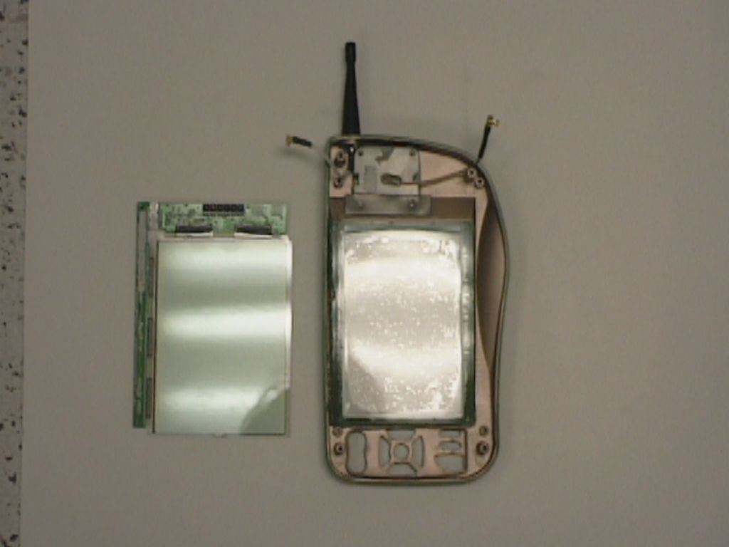
Handheld GPS Golf Computer - FCC ID OXKINFORMER2000 - GPS Industries Inc.
OXKINFORMER2000

Handheld GPS Golf Computer

Apr 16, 2000

Equipment Class

DSS - Part 15 Spread Spectrum Transmitter