OXX-SBC499Bicycle Light Transmitter
Specialized Bicycle Components Inc.
Click to zoom
Application Details
- Equipment Class
- DSC - Part 15 Security/Remote Control Transmitter
- Date of Grant
- Apr 27, 2000
- Application Purpose
- Original Equipment
- Date of Application
- Mar 22, 2000
- Equipment Note
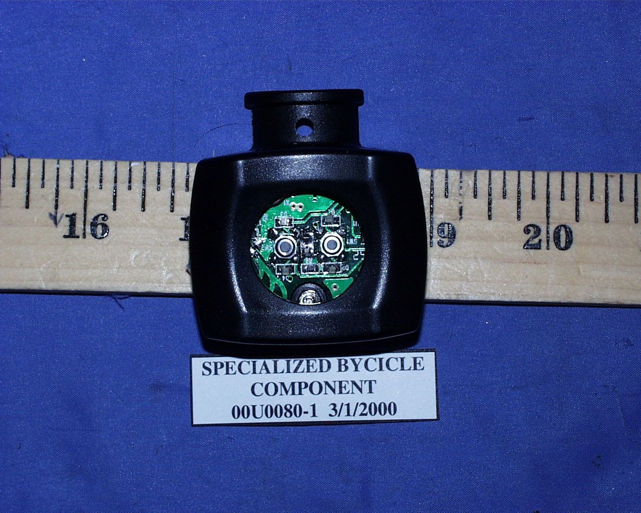
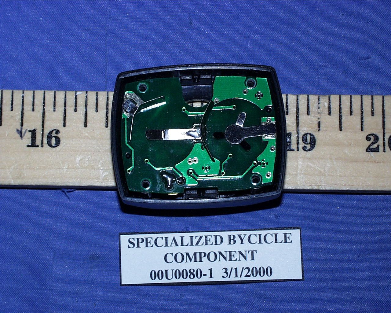
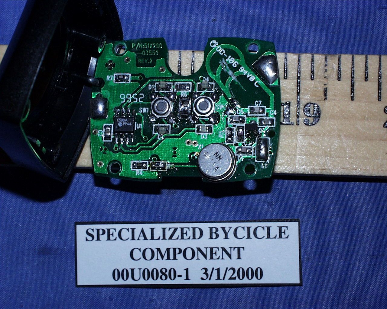
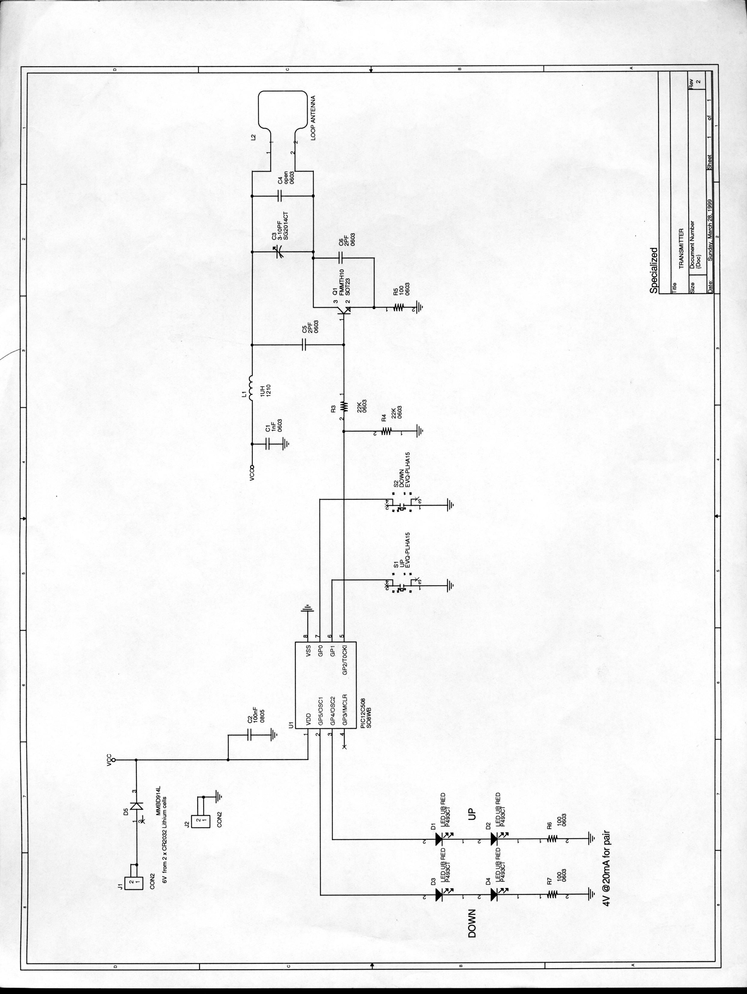
- Bicycle Light Transmitter
- Frequency Range
- 315.00000000 - 315.00000000
- Country
- United States
Documents & Files
Document Text
Text extracted from the exhibit documents filed with the FCC. Open a document above to read the original.
Users Manual
1 The battery pack of your FireBalls Comp has been shipped dis- charged. It needs to be completely charged before your first ride. Charge the battery continuously for 14 hours before your first ride. After 14 hours, you may remove the bat- tery from the charger (even if all 5 LEDs on the fuel gauge are not lit). After your first ride, allow the light to remain on until the battery is completely discharged and the light automatically turns itself off. This will help the fuel gauge to "learn" the battery’s capacity. The fuel gauge will become more accurate after 2 or 3 complete charge/discharge cycles. Please see the sections titled "Battery Pack" and "Charging the Battery" for more information. FireBalls ® Comp Lighting System. Congratulations on your purchase! You are now the owner of one of the world’s finest bicycle lighting systems. Your Specialized FireBalls Comp has been designed to provide the best combination of brightness, run-time, durability, ease of use and installation. WARNING: BICYCLING IN THE DARK IS AN INHERENTLY DANGEROUS ACTIVITY. No lighting system will guard you against inattentive motorists and other nighttime hazards. Always ride with extreme caution. Carry extra bulbs and some type of auxiliary light with you. Wear reflective clothing. Make sure your bicycle has the legally required reflectors and your helmet, ankles (or shoes) packs, panniers have reflectors or reflective patches. Specialized lights and lighting systems are not intended to replace your C.P.S.C. approved reflectors. Never remove the original reflectors from your bicycle. Always disconnect the battery pack and allow your light to cool before replacing it in the storage case. The FireBalls Comp features: • Retina Optical System – Allows Independent Adjustment of High And Low Beams • Wireless Handlebar Transmitter • Ultra High-Capacity Nickel Metal Hydride Battery with Integrated Fuel Gauge. • 4 Output settings (6, 12, 20, 32Watt) • Smart Battery Charger • Broken Filament Sensing • Die-cast A1 Premium Aluminum Housing • Universal Handlebar Mounts • Universal Helmet Mount • Battery Backpack • 20 Watt Halogen High Beam • 12 Watt Halogen Low Beam • Tail-light Port • Water Resistant Housing • 1 Year Warranty What is included in your FireBalls Comp package: 1. Lamp Housing (1) 2. Electronic Housing (1) 3. Battery Pack (1) 4. Helmet Mount (1) 5. Battery Backpack (1) 6. Handlebar Mounts (2) 7. Transmitter (1) 8. Battery Charger (1) 9. Wall Transformer (1) 10. Long Velcro ™ Strap (1) 11. Short Velcro Straps (2) 12. Cable Ties (2) 1 3 4 11 12 10 5 9 8 2 6 7 MOUNTING THE FIREBALLS COMP Your FireBalls Comp is designed to be mounted on your handlebars or on your helmet. Use a 3mm hex-wrench and the screws provided to install either the handlebar mounts or the helmet mount to the lamp housing. HANDLEBAR– Attach your FireBalls Comp securely to the handlebars with the quick-release handlebar mounts. The lamp housing should straddle the stem and may be mounted above or below the handlebars. Always use BOTH quick-release mounts. Slide the battery pack and electronics housing into one of your water-bottle cages. Use the long Velcro strap to secure the battery into the cage by wrapping it completely around the frame tube Secure the power cable to your frame with the two short Velcro straps. Be sure to leave enough slack in the power cable so that it will not hinder the rotation of your handlebars. Plug in the electrical connector between the battery and lamp housing. Make sure the power cable cannot become entangled in any of the moving components of your bicycle. HELMET– Attach your FireBalls Comp securely to your helmet by looping the Velcro strap through the vents. The angle of the helmet mount is adjustable. FireBalls Comp can be positioned on top or towards the front of your helmet. Secure the power cable to the back of your helmet with the two short Velcro straps. Drop the battery pack into the backpack. Be sure the fuel gauge lights can be seen through the slot in the back- pack. Put on the backpack and make sure all of the straps are secure and cannot become entangled in any of the moving components of your bicycle. For the most com- fortable fit use both the waist strap and the sternum strap. BATTERY PACK Your FireBalls Comp battery pack features an integrated fuel gauge that monitors the condition of the battery during use, while charging and in storage. Because it is located inside the battery housing, the FireBalls Fuel gauge will always give an accurate representation of the battery capacity. The five LED indicators show battery capacity in 20% increments. The lights will illuminate auto- matically when the light is in use and when the battery is charg- ing. To check the capacity when the battery is in storage simply press the button on the bat- tery. When the battery capacity is below 10% the first LED will blink. This is an indication that the pack is very low and should be charged as soon as possible. Use extreme care to avoid a short-circuit across the battery contacts.Never allow any metal objects to touch the contacts on the battery. In the event of a short-circuit, an Internal fuse will be tripped to avoid damage to the battery. The fuse will reset itself automatically when the short circuit is removed. CHARGING THE BATTERY The FireBalls Comp features the most advanced charging system ever offered in a bicycle lighting system. The charge cycle is controlled by the fuel gauge located within the battery pack. The system is designed to allow the battery to be left on the charger indefinitely, without the risk of overcharging the battery. When the battery is fully charged, the fuel gauge will signal the charger to stop charging. In order to counteract 2 the battery’s normal self-discharge characteristics during storage, the fuel gauge will occasionally turn on the charger to top-off the battery. To charge your battery pack, plug in the wire from the transformer into the charger base, unscrew the battery …
Text truncated - open the document above for the full version.
ID Label/Location Info
PROPOSED FCC ID LABEL AND LOCATION SPECIALIZED BICYCLE COMPONENTS INC. This device complies with Part 15 of the FCC Rules. Operation is subject to the following two conditions: (1) this device may not cause harmful interference, and (2) this device must accept any interference received, including interference that may cause undesired operation. FCC ID: OXX-SBC499 FCC ID LABEL FCC ID LABEL
Test Report
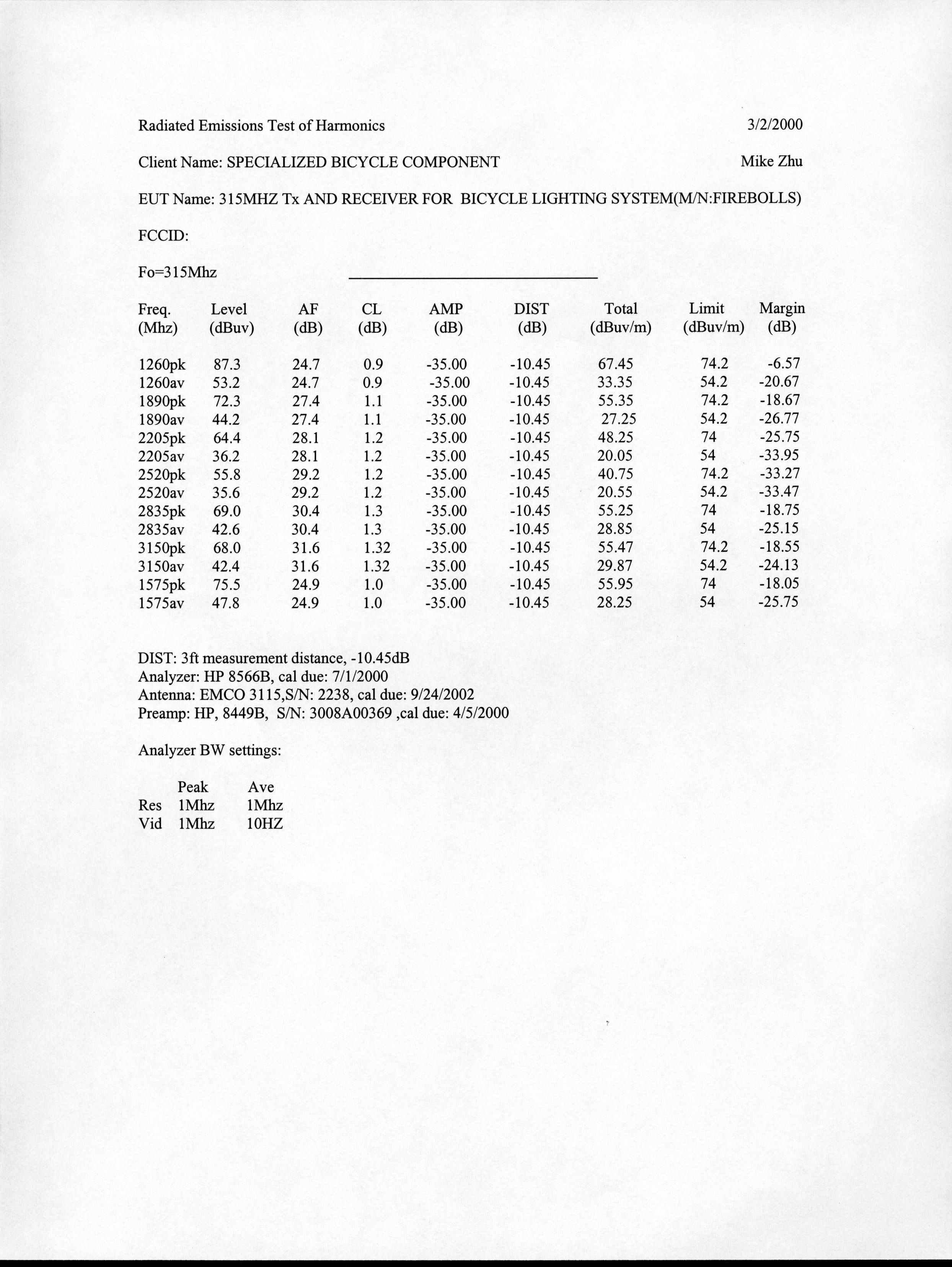
ELECTROMAGNETIC EMISSIONS COMPLIANCE REPORT CERTIFICATION TO FCC PART 15 REQUIREMENTS for INTENTIONAL RADIATOR 315 MHz TRANSMITTER FOR BICYCLE LIGHTING SYSTEM MODEL NO: 491-3210 FCC ID NO: OXX-SBC499 REPORT NO: 00U0080 ISSUE DATE: MARCH 02, 2000 Prepared for SPECIALIZED BICYCLE COMPONENTS INC. 15130 CONCORD CIRCLE MORGAN HILL, CA 95037 USA Prepared by COMPLIANCE ENGINEERING SERVICES, INC. d.b.a. COMPLIANCE CERTIFICATION SERVICES 1366 BORDEAUX DRIVE SUNNYVALE, CA 94089, USA TEL: (408) 752-8166 FAX: (408) 752-8168 REPORT NO:00U0080 FCC ID:OXX-SBC-499 DATE: MARCH 02, 2000 COMPLIANCE ENGINEERING SERVICES, INC.CCS DOCUMENT NO:CCSUP4020B 1366 BORDEAUX DRIVE, SUNNYVALE, CA 94089, USATEL:(408)752-8166 FAX:(408)752-8168 This report shall not be reproduced except in full, without the written approval of CCS. TABLE OF CONTENTS PAGE 1. VERIFICATION OF COMPLIANCE ........................................................................................ 1 2. Product Description..................................................................................................................... 2 3. Test Facility ................................................................................................................................. 2 4. Measurement Standards .............................................................................................................. 2 5. Test Methodology........................................................................................................................ 2 6. Measurement Equipment Used ...................................................................................................2 7. POWERLINE RFI LIMIT ..........................................................................................................3 8. RADIATED EMISSION LIMITS .............................................................................................. 3 9. SYSTEM TEST CONFIGURATION......................................................................................... 4 10. Test Procedure........................................................................................................................... 5 11. Equipment Modifications .......................................................................................................... 6 12. TEST RESULT ......................................................................................................................... 7 12.1 Maximum Modulation Percentage (M%) ............................................................................... 7 12.2 The Emissions Bandwidth....................................................................................................... 7 TEST DATA • Maximum Modulation Percentage Plot • Emission Bandwidth Plot • Radiated Emission Worksheet for Peak Measurement • Radiated Emission Worksheet for Average Measurement REPORT NO:00U0080 FCC ID:OXX-SBC499DATE: MARCH 02, 2000 PAGE NO: 1 COMPLIANCE ENGINEERING SERVICES, INC.CCS DOCUMENT NO:CCSUP4020B 1366 BORDEAUX DRIVE, SUNNYVALE, CA 94089, USATEL:(408)752-8166 FAX:(408)752-8168 This report shall not be reproduced except in full, without the written approval of CCS. 1. VERIFICATION OF COMPLIANCE COMPANY NAME :SPECIALIZED BICYCLE COMPONENTS INC. 15130 CONCORD CIRCLE MORGAN HILL, CA 95037 USA CONTACT PERSON :MARK SIMINOFF / PRODUCT DEVELOPER TELEPHONE NO.:408-779-6229-2379 EUT DESCRIPTION :315 MHz TRANSMITTER FOR BICYCLE LIGHTING SY STEM FCC ID:OXX-SBC499 DATE TESTED:MARCH 02, 2000 REPORT NUMBER:00U0080 TYPE OF EQUIPMENT(INTENTIONAL RADIATOR EQUIPMENT TYPE315 MHz TRANSMITTER MEASUREMENT PROCEDUREANSI C63.4 / 1992 LIM IT TYPEC ERT IF IC AT ION FCC RULECFR 47, PART 15 The above equipment was tested by Compliance Engineering Services, Inc. for compliance with the requirements set forth in CFR 47, PART 15. This said equipment in the configuration described in this report shows that maximum emission levels emanating from equipment are within the compliance requirements. T. N. COKENIAS / ENGINEERING DIRECTOR COMPLIANCE ENGINEERING SERVICES, INC. REPORT NO:00U0080 FCC ID:OXX-SBC499DATE: MARCH 02, 2000 PAGE NO: 2 COMPLIANCE ENGINEERING SERVICES, INC.CCS DOCUMENT NO:CCSUP4020B 1366 BORDEAUX DRIVE, SUNNYVALE, CA 94089, USATEL:(408)752-8166 FAX:(408)752-8168 This report shall not be reproduced except in full, without the written approval of CCS. 2. Product Description Fundamental Frequency 315MHz Power Source 6V Battery Transmitting Time Periodic < 5 seconds Associated Receiver MODEL: 491-3210, FCC DoC 3. Test Facility The 3/10/30 meter open area test site and conducted measurement facility used to collect the radiated data is located at 561F Monterey Road, Morgan Hill, California, U.S.A. A detailed description of the test facility was submitted to the Commission on May 27,1994. 4. Measurement Standards The site is constructed and calibrated in conformance with the requirements of ANSI C63.4/1992. 5. Test Methodology For an intentional radiator, the spectrum shall be investigated from the lowest radio frequency signal generated in the device, without going below 9 KHz, up to at least the tenth harmonic of the highest fundamental frequency or to 40 GHz, whichever is lower. (CFR 47 Section 15.33) 6. Measurement Equipment Used ManufacturerModel Number DescriptionCal Due Date H.P.8568ASpectrum Analyzer (100Hz – 1.5GHz) 02/01 H.P.8566BSpectrum Analyzer (100Hz – 22GHz) 09/00 EMCO3146Antenna (200-1000 MHz) 10/00 H.P.8447DPreamplifier (0.1 - 1300 MHz) 09/00 EMCO3115Antenna(1 - 18GHZ)11/00 H.P.8449BPreamplifier (1-26.5GHZ)03/00 REPORT NO:00U0080 FCC ID:OXX-SBC499DATE: MARCH 02, 2000 PAGE NO: 3 COMPLIANCE ENGINEERING SERVICES, INC.CCS DOCUMENT NO:CCSUP4020B 1366 BORDEAUX DRIVE, SUNNYVALE, CA 94089, USATEL:(408)752-8166 FAX:(408)752-8168 This report shall not be reproduced except in full, without the written approval of CCS. 7. POWERLINE RFI LIMIT CONNECTED TO AC POWER LINE SECTION 15.207 CARRIER CURRENT SYSTEM IN THE FREQUENCY RANGE OF 450 kHZ TO…
Text truncated - open the document above for the full version.
Contact Information
Applicant
Chris Zenthoefer(Product Manager)
[email protected]918-830-4202
Technical Contact
Compliance Engineering ServicesMike C.I. Kuo
[email protected]408-752-8166
1366 Bordeaux Drive · Sunnyvale, California · United States
Test Firm
Compliance Certification Services IncSteve Cheng
Technical Specifications
| # | Rule Parts | Frequency Range | Power Output |
|---|---|---|---|
| 1 | 15C | 315 MHz - 315 MHz | - |