OY3OPID433Offender Electronic Monitoring System
Guidance Monitoring Ltd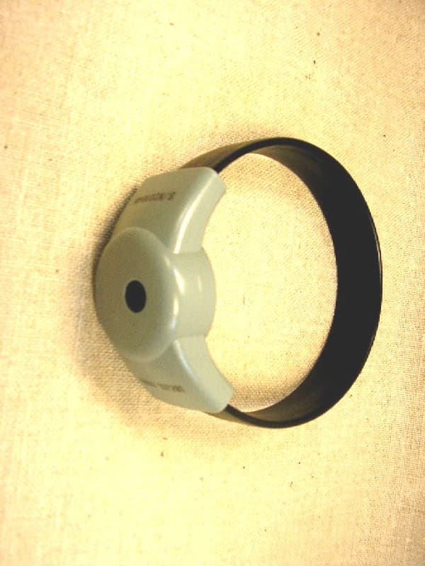
Click to zoom
Application Details
- Equipment Class
- DSC - Part 15 Security/Remote Control Transmitter
- Date of Grant
- Mar 17, 2006
- Application Purpose
- Original Equipment
- Date of Application
- Mar 17, 2006
- Equipment Note
- Offender Electronic Monitoring System
- Frequency Range
- 433.92000000 - 433.92000000
- Company
- Guidance Monitoring Ltd
- Country
- United Kingdom
Documents & Files
Document Text
Text extracted from the exhibit documents filed with the FCC. Open a document above to read the original.
Users Manual
1 Press to switch HHU on. Hand Held Unit PIN: ---- (C)2005 GCS LTD. GCS LTD 1. Install 2. De-install 3. Maintenance 4. RAM 20/02/2005 15:55:15 Main Menu Fit PID to subject. Align with new PID. Cancel Continue 20/02/2005 15:55:15 Fit PID Fit MU aerials. Position and plug in. Align with MU. Cancel Continue 20/02/2005 15:55:15 xxxxxx PID fitted MU is working correctly. Align with PID. Continue 20/02/2005 15:55:15 xxxxxx MU installed Subject should walk around edge of area. Align with MU. Continue 20/02/2005 15:55:15 PID Survey Range : xxx/xxx Align with PID. Continue 20/02/2005 15:55:15 Survey Results PID : xxxxxx MU : xxxxxx Range : xxx/xxx Align with MU. Cont 20/02/2005 15:55:15 Call Control ContinueContinue Wait for connection to complete. Align with MU. Redial 20/02/2005 15:55:15 Dialling... Done PID : xxxxxx MU : xxxxxx Range : xxx/xxx 20/02/2005 15:55:15 Installation complete 2 Enter your PIN code and press to proceed. 3 Press to select highlight- ed option: ‘1. Install’. 4 Fit the PID to the subject’s leg. 5 Align HHU with the PID and press to proceed. 6 Install MU, align HHU with the MU and press to proceed. 8 Accompany the subject around the limits of the curfew area. Then align HHU with the MU and press to proceed. 7 Align HHU with the PID and press to proceed. 9 Align HHU with the PID and press to proceed. HHU will display key informa- tion. Make a voice call to the control center and report the information. 10 Align HHU with the MU and press to proceed. PROBLEMS? See over for fault resolution details Do you wish to extend the survey period. No Yes 20/02/2005 15:55:15 Extended PID Survey Range : xxx/xxx Align with PID. Continue 20/02/2005 15:55:15 Survey Results Align with PID. Continue 20/02/2005 15:55:15 PID Survey Set HHU IMPORTANT: Switch HHU to use the appropriate frequency: • For origial MU1 (with removable aerials) - click switch up to 418 • For new MU2 (without aerials) - click switch down to 433 418 433 12 Installation should now be complete. Press to proceed. Refer to the PID bracelet fitting sheet for details. (For MU2 ignore mention of aerials). Offender Monitoring System If more time is needed for the survey: After 5 minutes, HHU will display Ü Choose option. If problems are encountered, see overleaf. 11 When connection is complete, align HHU with the MU and press to proceed. 13 Press to switch off the HHU. PID MU1 HHU PARTS MU2 or Link problems between HHU and PID or MU If any of these three screen are displayed, then there is a communication problem between the HHU and either the PID or the MU. To overcome, place the infrared window of the HHU as close as possible to the corresponding window of the other device and press to try again. See below for details about where the infrared win- dows are situated. |fault resolution| Problems at step 10 The screen shown here will be displayed if the PID being com- missioned is not listed within the MU. 1. Retry Get PID List 2. Retry Force Dial 3. Call Control 4. Cancel 20/02/2005 15:55:15 PID not in list This section lists screens that you may see if problems are encoutered and provides suggestions to overcome them. Possible causes and solutions • The control centre has not updated the system with the new PID and MU number. Press 3 on HHU to display the PID, MU and Range information. Voice call the control centre once again as per step 9 overleaf. Wait a few minutes before continuing further. • The MU cannot make contact with the control cen- tre system. Check the signal status on the MU display when it shows its standby screen. If no bars are shown then GSM reception may be insufficient. Try a different location. If successful in a different position, the full installation procedure MUST be repeated to gain the correct range settings. 15:55:15 20 February 2005 MU signal status Realign with MU & Retry Cancel Retry 20/02/2005 15:55:15 No Reply Realign with MU & Retry Cancel Retry 20/02/2005 15:55:15 No Reply Realign with PID & Retry Fail Retry 20/02/2005 15:55:15 No Reply Device infrared windows The HHU communicates with the PID and MU via infra- red. It is important to align the IR windows of the devices when they need to transfer information. HHU infrared window PID infrared window Infrared window MU1 MU2 Offender Monitoring System
Attestation Statements
Position Measurement ● Asset Location ● Personnel Tracking Guidance Monitoring Limited 4 Dominus Way, Meridian Business Park, Leicester, LE19 1RP, UK Tel: 44 (0) 116 2292600 Fax: 44(0) 116 2292604 Company Registered in England No. 02626613 VAT No. GB 860 2032 65 8 Febuary 2006 Attention: Application Examiner Reviewing Engineer Re: Request for confidentiality per Section 0.459 of FCC Rules Applicant: Guidance Monitoring Limited. FRN: 0014497887 FCC ID: OY3OPID433 To whom it may concern, Request is hereby submitted by Guidance Monitoring Limited., to withhold from public review certain portions of the application for equipment certification for the referenced FCC identifier. In particular, the following sections of the application and report are requested to be kept confidential: • Schematics • Detailed Block diagrams • Detailed Operational/Functional Description • Internal photos Rationale for request for confidentiality: Security Product, used for tagging offenders Guidance Monitoring Limited wishes to keep these items confidential to maintain a competitive advantage in the marketplace. The $145 fee for confidentiality has been submitted along with the fee for certification. If you have questions or need further information, please contact the undersigned. Sincerely, JOHN POTTER
Attestation Statements
From: Terre Wolak ES-Atl Sent: Monday, March 06, 2006 10:07 AM To: Suresh Kondapalli ES-Mpk Subject: FW: OY3OPID433 Suresh, FYI........let me know if you need anything further to certify. Regards, Terre -----Original Message----- From: John Potter [mailto:[email protected]] Sent: Monday, March 06, 2006 12:34 PM To: Terre Wolak ES-Atl Subject: RE: OY3OPID433 Hi Terre Sorry for the delay again. Please find my proposed response to Suresh, I will put a label in the post tomorrow. I am reviewing Your TCB application for OY3OPID433, I have following observations and need the some information from you. 1) Block Diagram showing Frequency of all oscillators and signal path from input to output, is mandatory as per FCC part 2.1033(b)(5) Crystal CS2 is a 13.56MHz crystal oscillator; there are no other RF crystals in the device. Data is input via the FSKDTA input and output onto the antenna via a matching network. 2) Do you have any user manual for this device? I have seen System brochure and Installation quick guide with this submission but not user manual. We don’t have a user manual as we rent these devices to a very restricted set of customers who will only read our ‘Quick Install Guide’, do we have to have a user manual to be able to get approval? If so what are the bare bones requirements for the document? 3) You have requested that internal photos should be kept confidential. FCC requires additional justification for this. For example "special tools required" to open the device. The other option is, Internal Photos can be designated for short term confidentiality (90 days) without additional justification. Please furnish additional justification or amend confidentiality request letter and mail it to me. Special Tools Required, It is not possible to open the device at all, it is welded together before despatch to the customer. All repairs and servicing require return of the devices to the manufacturer where the electronics are cut out of the plastic case using a special cutting tool. 4) What is antenna used for device and its gain?. The device contains a loop antenna, which is housed inside the welded enclosure; it is not possible for a user to change the antenna, the antenna has a gain of approximately 1. 5) Revised label as indicated by Terre earlier. Guidance Monitoring Limited PIDGCS201345 FCC ID# OY3OPID433 If have any questions, please do not hesitate to ask me Thanks, Best Regards, Suresh Kondapalli -----Original Message----- From: Terre Wolak ES-Atl Sent: Friday, February 10, 2006 11:39 AM To: John Potter Cc: Suresh Kondapalli ES-Mpk; David Schramm ES-Atl Subject: RE: OY3OPID433 John, FYI, Suresh Kondapalli in our Menlo Park facility will now be handling review for your product. When you send the revised label to me please cc Suresh. Attached is the revised test report with the new FCC ID number. Regards, Terre -- No virus found in this incoming message. Checked by AVG Free Edition. Version: 7.1.375 / Virus Database: 268.1.1/273 - Release Date: 02/03/2006 -- No virus found in this outgoing message. Checked by AVG Free Edition. Version: 7.1.375 / Virus Database: 268.1.2/274 - Release Date: 03/03/2006 This e-mail (and any attachment) is intended only for the attention of the addressee(s). Its unauthorised use, disclosure, storage or copying is not permitted. If you are not the intended recipient, please destroy all copies and inform the sender by return e-mail. Internet e-mail is not a secure medium. Any reply to this message could be intercepted and read by someone else. Please bear that in mind when deciding whether to send material in response to this message by e-mail. This e-mail (whether you are the sender or the recipient) may be monitored, recorded and retained by Guidance Limited. E-mail monitoring / blocking software may be used, and e-mail content may be read at any time. You have a responsibility to ensure laws are not broken when composing or forwarding e-mails and their contents.
Cover Letter(s)
Position Measurement ● Asset Location ● Personnel Tracking Guidance Monitoring Limited 4 Dominus Way, Meridian Business Park, Leicester, LE19 1RP, UK Tel: 44 (0) 116 2292600 Fax: 44(0) 116 2292604 Company Registered in England No. 02626613 VAT No. GB 860 2032 65 Letter of Agency I appoint Intertek Testing Services NA Inc. to act on our behalf in front of the Federal Communications Commission with respect to all matters relating to certification of equipment under the FCC rules until further notice. I further certify that no party (as defined in 1.2002 of CFR 47, 1995) to this application, including myself, is subject to denial of federal benefits, that includes FCC benefits, pursuant to Section 5301 of the Anti-Drug Abuse Act of 1988, 21 U.S.C.,853A. Equipment: Security Tag OPID 433MHz FCC ID: OY3OPID433 Dated this 8 day of Febuary 2006. Signature ____________________________________ Name ______John Potter______________________ Title ______Director ________________________ Company _____Guidance Monitoring Limited_______ Telephone _____+441162292605_________________
External Photos
Intertek Model #: OPID 433MHZ FCC ID: OY3PID23 A2LA Code:121624 1 of 2 External Equipment Photographs Photograph 1: Overview Intertek Model #: OPID 433MHZ FCC ID: OY3PID23 A2LA Code:121624 2 of 2 Photograph: 1 Overview OPID 433MHZ
Test Report
EMC Report for Guidance Ltd. on the PID FCC Part 15.231 File: 3085182-37-1-2 FCC ID: OY3OPID433 Page 1 of 15 TEST REPORT Report Number: 3085182-37-1-2 Project Number: 3085182 February 13, 2006 Testing performed on the Model Number: OPID 433MHZ to FCC Part 15.231 For Guidance Monitoring, Ltd. Test Performed by: Test Authorized by: Intertek ETL Semko 1950 Evergreen Blvd, Suite 100 Duluth, GA 30096 Guidance Monitoring, Ltd. 4 Dominus Way Meridian Business Park Leicester, LE19 1RP England Prepared by: Date: February 13, 2006 Troy Ihle, Senior Associate Engineer Reviewed by: Date: February 13, 2006 Jeremy Pickens, EMC Team Leader All services undertaken are subject to the following general policy: This report is for the exclusive use of Intertek's Client and is provided pursuant to the agreement between Intertek and its Client. Intertek's responsibility and liability are limited to the terms and conditions of the agreement. Intertek assumes no liability to any party, other than to the Client in accordance with the agreement, for any loss, expense or damage occasioned by the use of this report. Only the Client is authorized to copy or distribute this report and then only in its entirety. Any use of the Intertek name or one of its marks for the sale or advertisement of the tested material, product or service must first be approved in writing by Intertek. The observations and test results in this report are relevant only to the sample tested. This report by itself does not imply that the material, product, or service is or has ever been under an Intertek certification program. This report must not be used to claim product endorsement by A2LA, NIST, or any agency of the US Government. Intertek EMC Report for Guidance Ltd. on the PID FCC Part 15.231 File: 3085182-37-1-2 FCC ID: OY3OPID433 Page 2 of 15 TABLE OF CONTENTS 1Summary of Tests ......................................................................................................................... 3 2General Description ...................................................................................................................... 4 2.1Product Description ........................................................................................................... 4 2.2Related Submittal(s) Grants ............................................................................................... 4 2.3Test Methodology .............................................................................................................. 4 2.4Test Facility ....................................................................................................................... 5 3System Test Configuration........................................................................................................... 5 3.1Support Equipment ............................................................................................................5 3.2Cabling............................................................................................................................... 5 3.3Block Diagram of Test Setup............................................................................................. 5 3.4Justification ........................................................................................................................ 6 3.5Software Exercise Program................................................................................................ 6 3.6Mode of Operation During Test......................................................................................... 6 3.7Modifications Required for Compliance ........................................................................... 6 3.8Additions, deviations and exclusions from standards ........................................................ 6 4Measurement Results.................................................................................................................... 7 4.1Radiated Emission ............................................................................................................. 7 4.1.1Procedure ............................................................................................................... 7 4.1.2Field Strength Calculation ..................................................................................... 7 4.1.3Test Result ............................................................................................................. 8 4.2AC Line Conducted Emission ........................................................................................... 9 4.2.1Measurement Procedure ........................................................................................ 9 4.2.2Test Result ............................................................................................................. 9 4.3Occupied Bandwidth Plot .................................................................................................. 10 4.4Transmitter Duty Cycle Calculation and Measurements ................................................... 11 4.5Reduced Field Strengths FCC Rule 15.231(e)................................................................. 12 5List of test equipment ................................................................................................................... 14 6Document History ......................................................................................................................... 15 INDEX OF FIGURES Figure 4-1: Bandwidth plot ......................................................................................................................... 10 Figure 4-2: Output – 100 milliseconds ....................................................................................................... 11 Figure 4-3: Output - 100 Seconds.....................................................................................13 INDEX OF TABLES Table 4-1: Radiated Emissions – Fundamental & Spurious Emissions .........…
Text truncated - open the document above for the full version.
Test Setup Photos
Intertek Model #: OPID 433MHZ FCC ID: OY3PID23 A2LA Code:121624 1 of 3 Test Setup Photographs Photograph 1: Radiated Emissions – Front Photograph 2: Radiated Emissions - Back Intertek Model #: OPID 433MHZ FCC ID: OY3PID23 A2LA Code:121624 2 of 3 Photograph: 1 Radiated Emissions - Front OPID 433MHZ Intertek Model #: OPID 433MHZ FCC ID: OY3PID23 A2LA Code:121624 3 of 3 Photograph: 2 Radiated Emissions - Back OPID 433MHZ
Contact Information
Applicant
Malcolm Thomas Roberts(Managing Director)
Technical Contact
Guidance MonitoringJohn Potter
[email protected]+441162292605
4 Dominus Way · Leicester · United Kingdom
Test Firm
Intertek Testing ServicesDavid Schramm
Technical Specifications
| # | Rule Parts | Frequency Range | Power Output |
|---|---|---|---|
| 1 | 15.231(e) | 433.92 MHz - 433.92 MHz | - |
Other Applications from Guidance Monitoring Ltd
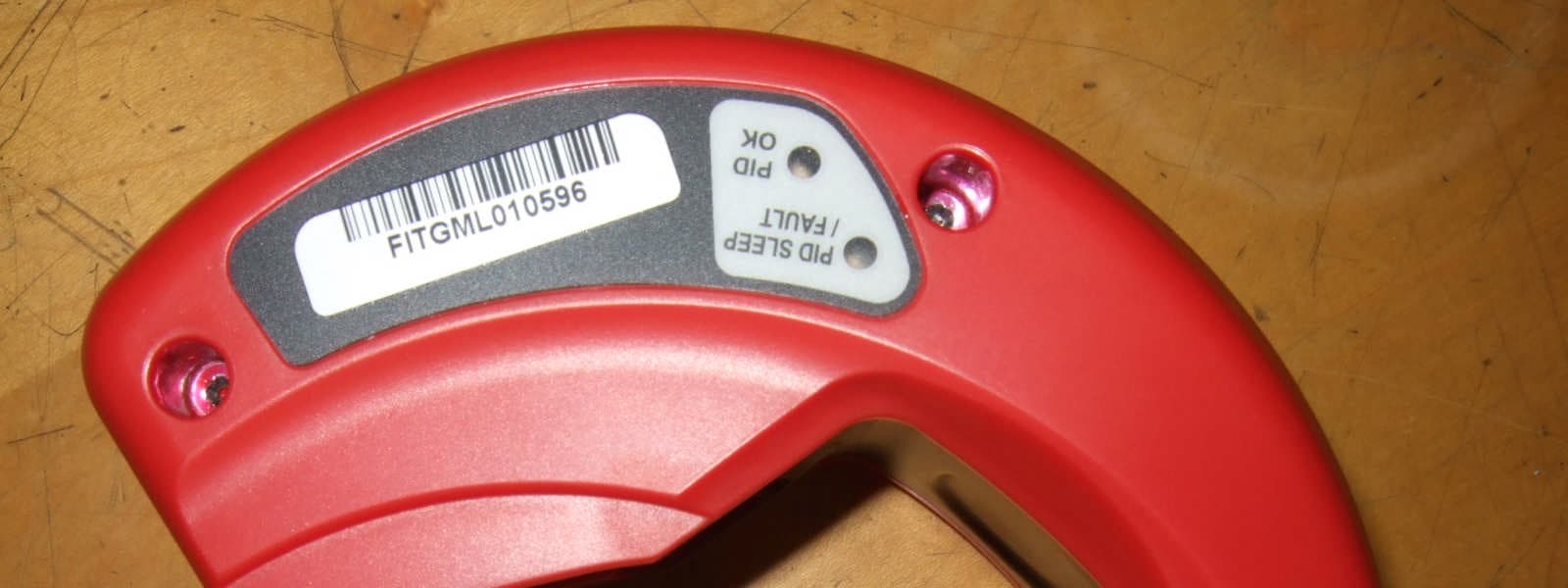
OY3FITTINGTOOL433
Aug 08, 2011Installation Tool
Equipment Class
DSR - Part 15 Remote Control/Security Device Transceiver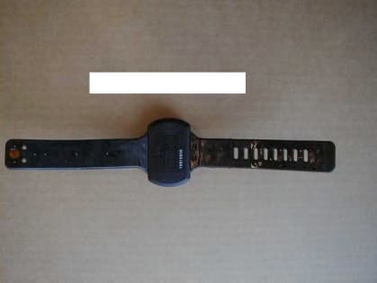
OY3PID23
May 03, 2000Offender Monitoring System
Equipment Class
DSC - Part 15 Security/Remote Control Transmitter