OZ2TT04Temperature Data Transceiver
KatchAll Technology Group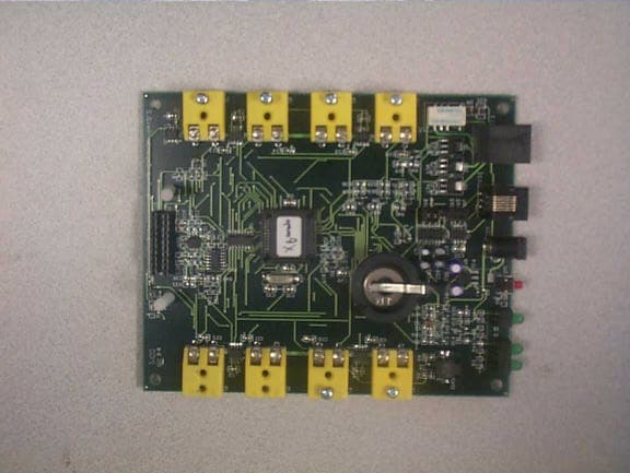
Click to zoom
Application Details
- Equipment Class
- DXT - Part 15 Low Power Transceiver, Rx Verified
- Date of Grant
- Jan 04, 2001
- Application Purpose
- Original Equipment
- Date of Application
- Nov 27, 2000
- Equipment Note
- Temperature Data Transceiver
- Frequency Range
- 905.90000000 - 916.60000000
- Company
- KatchAll Technology Group
- Country
- United States
Documents & Files
Document Text
Text extracted from the exhibit documents filed with the FCC. Open a document above to read the original.
Users Manual
Registration Card User Information ○○○○○○○○○○○○○○○○ ○○○○○○○ Hardware Serial Numbers ○○○○○○○ ○○○○○○○○○○ Commanders Sentries Echos XPs Liberators Communicators 2000, KatchAll Technology Group, Inc. — All Rights Reserved — Temp Trak & Temp Trak Plus are products of the KatchAll Technology Group. Questions ○○○○○○○○ ○○○○○○○○○○○○○○○○○○○○ First Name Middle Initial Last Name Name of Establishment, Organization or CompanyStreet Address City State ZIP Code Phone E-Mail ( ) ( ) FAX What kind of food service operation isyour establishment? £ Independent Restaurant £ Chain Unit Company Store £ Chain Unit Franchise Store £ Caterer £ Health Care Provider £ School System £ Lodging Property £ Correctional Facility £ Private Club £ In-House Food Service £ Other:_______________ How did you hear about Temp Trak? £ Advertisement £ Dealer Recommendation £ KatchAll Factory Representative £ Another Food Service Operator £ Health & Safety Inspector £ Trade Article £ Trade Show Visit £ Other:_______________ Who purchased your Temp Trak orTemp Trak Plus system? £ Owner / Operator £ Chain HQ Management £ Organizational Management How do you intend to use your TempTrak System? £ Inventory Processing / Control £ Fixed Temperature Monitoring £ Random Temperature Monitoring £ HACCP Monitoring £ Check on Employee Monitoring Routine £ Product Rotation Tool £ Prepared Product Tracking / Use Tool £ Use By Dating Tool £ Non-Food Temperature Monitoring £ After-Hours Monitoring / Alerting onTemperatures This registration card must be completed and returned to KatchAll Technology Group, Inc. within30 days of purchase in order to validate the warranty on your new Temp Trak software andhardware components.By registering your Temp Trak system, you will receive free software upgrades for one year frompurchase date and notification of any new modules or advances to the system. 5800 Creek Road Cincinnati, OH 45242 PLACE STAMP HERE KatchAll Technology Group, Inc. A wholly owned subsidiary of KatchAll Industries International, Inc. 5800 Creek Road Cincinnati, OH 45242 FAX 513-793-4895 www.katchall.com 2000, KatchAll Technology Group, Inc. Patents Pending, All Rights Reserved, Printed in USA Version 1.0.1 4 INTRODUCTION 5 Congratulations! Temp Trak is a quantum leap into the future of food service management, and you have its benefits today. With Temp Trak, you possess the most advanced total quality management and time-on-task breakthrough in the history of our industry. It is easy to learn and user friendly to operate. Temp Trak is a unique, innovative system that gives you the capability to read and record temperatures, and with Temp Trak Plus — track inventory, all automatically! Both Temp Trak and Temp Trak Plus are wireless, accurate and global, allowing man- agement to obtain precise operating information anytime, any- where. Welcome to the world of Temp Trak, the new standard in food service management from KatchAll Technology Group — Bring- ing you the Future in Food Safety! Need Help?! Temp Trak and Temp Trak Plus include a wide range of on-line help files that assist with many common problems. For instance, if you’re having trouble setting up a new printer, on-line help will guide you through the process — just click on the Help button, it’s that easy! If you would like to visit our web site, direct your browser to: http://www.katchall.com There you will find answers to commonly asked questions, soft- ware upgrades and new products. Warranty & FCC Licensing Temp Trak and Temp Trak Plus both come with a standard 90 day warranty on parts and labor. The Temp Trak units have been tested and found to comply with the limits for a Class A digital device, pursuant to Part 15 of the FCC rules. Operation is subject to the following two conditions: 1. This device may not cause harmful interference, and 2. This device must accept any interference that may cause undesired operation. INTRODUCTION 6 END-USER LICENSE AGREEMENT FOR TEMP TRAK SOFT- WARE IMPORTANT – READ CAREFULLY: This End-User license Agreement (“EULA”) is a legal agreement between you (either an individual or a single entity) and KatchAll Technology Group, Inc. (“KatchAll”) for the Temp-Trak software product identified above, which includes computer software and may include associated media, printed materials, and “online” or electronic documentation (“SOFTWARE PRODUCT”). The SOFTWARE PRODUCT also includes any updates and supplements to the original SOFTWARE PRODUCT provided to you by KatchAll. Any software provided along with the SOFTWARE PRODUCT that is associated with a separate end-user license agreement is licensed to you under the terms of that license agreement. By installing, copying, downloading, accessing or otherwise using the SOFTWARE PRODUCT, you agree to be bound by the terms of this EULA. If you do not agree to the terms of this EULA, do not install or use the SOFTWARE PRODUCT; you may, however, return it to your place of purchase for a full refund. SOFTWARE PRODUCT LICENSE The SOFTWARE PRODUCT is protected by copyright laws and international copyright treaties, as well as other intellectual property laws and treaties. The SOFTWARE PRODUCT is licensed, not sold. 1.GRANT OF LICENSE. This EULA grants you the following rights: •Systems Software. You may install and use one copy of the SOFTWARE PRODUCT on a single computer, including a workstation, terminal or other digital electronic device (“COMPUTER”). •Storage/Network Use. You may also store or install a copy of the SOFTWARE PRODUCT on a storage device, such as a network server, used only to install or run the SOFTWARE PRODUCT on your other COMPUTERS over an internal network; however, you must acquire and dedicate a license for each separate COMPUTER on or from which the SOFTWARE PRODUCT is installed, used, accessed, displayed or run. A license for the SOFTWARE PRODUCT may not be shared or used concurrently on different COMPUTERS. 2.DESCRIPTION OF OTHER RIGHTS AND LIMITATIONS. •Academic E…
Text truncated - open the document above for the full version.
Users Manual
TempTrak Sentry XP Wireless Temperature Sensor Operating Instructions Revision A Katchall Technology Group 5800 Creek Road Cincinnati, Ohio 45242 (800) 533-6900 TempTrak Sentry XP Instruction Manual Katchall Technology Group2Revision A Owner’s Record The serial number for the TempTrak Sentry XP unit is located on the bottom of the plastic housing. Record the serial number in the space provided below. Refer to this number whenever you call upon your Katchall dealer regarding this product. Serial Number: TTE______________TT Important Safety Instructions When using the Temptrak Sentry XP unit, observe the following safety instructions: 1. Read and understand all instructions. 2. Unplug this product from the wall outlet before cleaning. Wipe with a damp cloth to clean. Avoid getting moisture on the electronic connections. 3. Do not submerge the product in a liquid. Damage to the electronics will occur. Enclose the device in a watertight plastic container prior to placing the unit in a moist environment. 4. Securely fasten the unit to a wall, shelf, etc. Failure to do so may result in the unit falling to the ground, possibly damaging the product. 5. This unit should only be powered by the plug-in power converter provided with the unit or through the internal battery backup system. 6. Do not locate this unit where the power cord may become a tripping hazard. 7. Do not disassemble the product. Contact your Katchall dealer if problems arise in the operation of the unit. The TempTrak Sentry XP unit can be operated in a backup manner (i.e. loss of primary power) via the internal “coin” batteries provided with the unit. Observe the following instructions to avoid injury to persons or food products: 1. Use only the batteries provided with the unit. These batteries can only be replaced at the factory. 2. Do not dispose of Sentry XP units in a fire. The batteries contained on the board may explode. Check with local codes for possible special disposal instructions. Wireless Operation The TempTrak Sentry XP unit communicates to the other devices in the TempTrak system via radio frequency (RF) energy. Careful placement of the unit is required to insure consistent RF communications with other TempTrak devices. The following general considerations apply to placement of the TempTrak Sentry XP unit: 1. In general, the TempTrak Sentry XP unit will communicate with a TempTrak Commander or Echo unit at ranges up to 150 feet. This range applies only to clear line-of-sight transmission in which there are no physical obstructions between the TempTrak Sentry XP unit and the TempTrak Commander unit. A simple way to insure line-of-sight transmission is to verify that you can physically see one unit when standing at eye level with the other unit. 2. The TempTrak Sentry XP unit will communicate with other TempTrak devices through walls. The range at which communication through a wall can be achieved is a function of the materials from TempTrak Sentry XP Instruction Manual Katchall Technology Group3Revision A which the wall is constructed. Any solid metallic materials greater than 1 square foot in area within the direct transmission path will block the RF transmissions. In general, the following rule of thumb can be used for transmission ranges through interior walls (drywall construction is assumed, actual performance will vary significantly due to differences in construction material and their subsequent impact on RF transmission): 0 walls ‡ 150 feet 1 wall ‡ 75 feet 2 walls ‡ 50 feet 3 walls ‡ 35 feet 4 walls ‡ 25 feet 5 walls ‡ 15 feet 3. Do not place the TempTrak Sentry XP unit near a cordless telephone base unit. Interference may result. 4. Operation of cordless phones and cell phones in near proximity to the TempTrak Sentry XP unit may result in interference. Information To The User NOTE: The TempTrak Sentry XP unit has been tested and found to comply with the limits for a Class B digital device, pursuant to part 15 of the FCC rules. These limits are designed to provide reasonable protection against harmful interference in a residential installation. This equipment generates, uses and can radiate radio frequency energy and, if not installed and used in accordance with the instructions, may cause harmful interference to radio communications. However, there is no guarantee that interference will not occur in a particular installation. If this equipment does cause harmful interference to radio or television reception, which can be determined by turning the equipment off and on, the user is encourage to try to correct the interference by one or more of the following measures: 1. Reorient or relocate the receiving antenna. 2. Increase the separation between the equipment and receiver. 3. Connect the equipment into an outlet on a circuit different from that to which the receiver is connected. 4. Consult the dealer or an experienced radio/TV technician for help. Caution To User: changes or modifications to this equipment that are not expressly approved by the party responsible for FCC compliance could void the user’s authority to operate this equipment. System Operation Please refer to the TempTrak system operations manual for detailed instructions on how to place and integrate TempTrak Sentry XP units into a fully operational TempTrak system.
Attestation Statements
Confidentiality Request TempTrak Sentry XP Unit The following submitted items are requested to be kept confidential: 1. Bill of Material 2. Schematics 3. Block Diagrams
Cover Letter(s)
To: Federal Communications Commission Critical Link Inc. hereby requests the certification of its transceiver model Name TempTrak Sentry XP. It's a transceiver designed to collect temperature data in an industrial environment. The Sentry XP certification will be held by: KatchAll Technology Group 5800 Creek Road Cincinnati, Ohio 45242 (513) 793-5366 TIN 31-1037180 Contact: Jack Kennamer Certain parts of this submittal are of a confidential nature, and confidentiality is requested under FCC rules part 0, section 459. attached are - Letter of Authorization and drug statement (Letter of Agency.pdf) - Confidentiality request (Confidentiality.PDF) - Test report for the TempTrak Sentry XP (Report.pdf) - Certification Photos (Cert Photos.pdf) - Setup Photos (Setup photos.pdf) - Copy of the proposed product label (FCC label.pdf) - User manual (TempTrakUsersGuide.pdf) - Operating Instructions (operating instructions.pdf) - Label Location (Label Location.pdf) The following items fall under the confidentiality request - Block diagram (CONF-BlockDiagram.pdf) - Schematics (CONF- Schematic.pdf) - Bill of Material (CONF-Bom rf.pdf, CONF-Bom xp.pdf) With regards Cand y L. Ca mpbell email: [email protected] Phone:(978)635-8540 Inte rtek Testing Services NA Inc. 70 Codma n Hill Road Boxborough, MA 01719 Telephone (978) 263-2662 Fax (978) 263-7086
ID Label/Location Info
Label Location
ID Label/Location Info
The “Sentry XP” Label (attached to the bottom of the unit, 3.0” x 1.5”): FCC ID: XXXXXXX
ID Label/Location Info
The “Sentry XP” Label (attached to the bottom of the unit, 3.0” x 1.5”): FCC ID: OZ2TT04
ID Label/Location Info
Label Location
Internal Photos
TempTrack Sentry XT Back View TempTrack Sentry XT Front View TempTrack Sentry XT Side View TempTrack Sentry XT Bottom View TempTrack Sentry XT Power Cube TempTrack Sentry XT Internal View TempTrack Sentry XT Top View of Control Board TempTrack Sentry XT Bottom View of Control Board TempTrack Sentry XT Top View of RF Board TempTrack Sentry XT Bottom View of RF Board
Test Report
Intertek Testing Services NA, Inc. Emissions Testing Performed on the Critical Link Transceiver Model: TempTrak Sentry XP To FCC Part 15 Subpart B and Subpart C, Section 15.249 Date of Test: September 15, 2000 Page 1 of 27 Report Number: J20022272 Contact: Mr. John Fayos All services undertaken are subject to the following general policy: Reports are submitted for exclusive use of the client to whom they are addressed. Their significance is subject to the adequacy and representative character of the samples and to the comprehensiveness of the tests, examinations or surveys made. No quotations from reports or use of Intertek Testing Services NA Inc. name is permitted except as expressly authorized by Intertek Testing Services NA Inc. in writing. This report must not be used to claim product endorsement by NVLAP, NIST or any other agency of the U.S. Government. Intertek Testing Services NA, Inc. Part 15 Laboratory Measurements and ANSI C63.4-1992Job Number: J20022272 Revision March 24, 2000Page 2 of 27 This document may not be reproduced except in its entirety without written permission from ITS. Table of Contents TABLE OF CONTENTS....................................................................................................................................................................................2 I – INTRODUCTION AND SUMMARY..........................................................................................................................................................3 II – TECHNICAL REQUIREMENTS................................................................................................................................................................4 15.1SCOPE...........................................................................................................................................................................................4 15.15GENERAL TECHNICAL REQUIREMENTS............................................................................................................................4 15.27SPECIAL ACCESSORIES...........................................................................................................................................................5 15.31MEASUREMENT STANDARDS...............................................................................................................................................5 15.33 FREQUENCY RANGE OF MEASUREMENT..........................................................................................................................5 15.35MEASUREMENT DETECTOR FUNCTIONS AND BANDWIDTH......................................................................................6 15.36TRANSITION PROVISIONS......................................................................................................................................................6 15.105INFORMATION TO THE USER................................................................................................................................................6 15.107CONDUCTED LIMITS................................................................................................................................................................7 15.109 RADIATED EMISSION LIMITS................................................................................................................................................9 15.111 ANTENNA POWER CONDUCTION LIMITS FOR RECEIVERS........................................................................................10 15.201CERTIFICATION.......................................................................................................................................................................10 15.203 ANTENNA REQUIREMENTS.................................................................................................................................................11 15.204EXTERNAL RADIO AMPLIFIER............................................................................................................................................11 15.205RESTRICTED BANDS OF OPERATION................................................................................................................................11 15.207 CONDUCTED LIMITS..............................................................................................................................................................11 15.209RADIATED EMISSION LIMITS; GENERAL REQUIREMENTS.........................................................................................11 15.249OPERATION WITHIN THE BANDS 902-928 MHZ, 2400-2483.5 MHZ, 5725-5875 MHZ, AND 24.0-24.25 GHZ.......12 2.201EMISSION MODULATION AND TRANSMISSION CHARACTERISTICS.......................................................................13 2.1041MEASUREMENT PROCEDURES...........................................................................................................................................13 2.1091 RADIOFREQUENCY RADIATION EXPOSURE EVALUATION: MOBILE DEVICES.................................................13 2.1093 RADIOFREQUENCY RADIATION EXPOSURE EVALUATION: PORTABLE DEVICES............................................13 III - ATTESTATION.........................................................................................................................................................................................14 IV - SITE DESCRIPTION AND MEASUREMENT EQUIPMENT.............................................................................................................15 V – SUMMARY OF EQUIPMENT UNDER TEST.......................................................................................................................................17 VI - CONFIGURATION INFORMATION.....................................................................................................................................................18 VII - CONFIGURATION PHOTOGRAPHS..........…
Text truncated - open the document above for the full version.
Test Setup Photos
Radiated Emissions setup front View Radiated Emissions setup back View Conducted Emissions setup front View Conducted Emissions setup Back View
Contact Information
Applicant
Jack Kennamer(Engineer)
(513) 793-5366
Technical Contact
Intertek Testing ServicesCandy L Campbell
[email protected](978) 263-2662
70 Codman Hill Road · Boxborough, Massachusetts · United States
Non-Technical Contact
Intertek Testing ServicesCandy L Campbell
[email protected](978)263-2662
Test Firm
Intertek Testing Services NA Inc.Robert Martin
Technical Specifications
| # | Rule Parts | Frequency Range | Power Output | Tolerance |
|---|---|---|---|---|
| 1 | 15C | 905.9 MHz - 916.6 MHz | - | % |