OZ5URC-200RF REMOTE CONTROLLER
Ohsung Electronics Co., Ltd.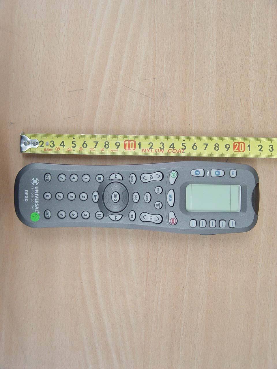
Click to zoom
Application Details
- Equipment Class
- DSC - Part 15 Security/Remote Control Transmitter
- Date of Grant
- Apr 25, 2006
- Application Purpose
- Original Equipment
- Date of Application
- Apr 25, 2006
- Equipment Note
- RF REMOTE CONTROLLER
- Frequency Range
- 417.50000000 - 418.50000000
- Company
- Ohsung Electronics Co., Ltd.
- Country
- South Korea
Documents & Files
Document Text
Text extracted from the exhibit documents filed with the FCC. Open a document above to read the original.
Users Manual
Test Report No.: GETEC-E3-06-018 FCC Part 15 Subpart C EUT Type: RF Remote Controller APPENDIX I : USER’S MANUAL FCC ID.: OZ5URC-200 1 2 The RF10 Remote WELCOME CONTNETS The RF10 Remote LOCATION OFCONTROLS Keypad Layout 3 GETTINGSTARTED Overview 4 Battery Installation 4 Activating Component Commands 5 The SHIFT Button 6 The LIGHT Button 6 BASICSETUP Overview 7 Pre-Programmed Code Method 7 Pre-Programmed Auto-Search Method 11 Learning Method 13 Transmitting (Busy Signal) Icon 16 Child Lock Feature 16 ADVANCEDSETUP Customizing Component Names on the LCD Screen 17 MacroPower TM Setup 19 SimpleSound TM Setup & Other ‘Punch Throughs’ 21 AUX Function: Programming an 8th Component 23 Recalling Pre-programmed Setup Code Numbers 25 ERASINGCOMMANDS Erasing Learned Button, Macro or Favorite Channel Commands 27 Re-setting RF10 to Original Factory Default Settings 33 THE OPTIONALPOWERBLASTER TM PowerBlaster TM 35 PRE-PROGRAMMEDCODE TABLES TV 39 CABLE 42 DVD 44 VCR 47 AUDIO 49 SAT 52 CD 54 AUX 56 Pre-Programmed Code Tables 38 COMMANDLOCATIONS Location of commands 58 PRE-PROGRAMMEDCODE NOTES Pre-Programmed Code Notes 37 OTHERINFO Frequently Asked Questions 67 Specifications/Warranty 68 Congratulations on purchasing Universal Remote Control’sMASTERCONTROL TM RF10 Pre-programmed and Learning Remote Control! You now have the power to control your entirehome entertainment system with one easy-to-use remote. TheRF10 can be used with thousands of audio/video Componentsbecause of the extensive code library pre-programmed into theremote. And, the RF10’s impressive lineup of special advancedfeatures can automate and customize the operation of yoursystem in many ways. So... get ready to sit back, relax andsimplify your home entertainment experience.The Quick Setup DVD Program Guide supplied with the RF10will assist you in programming your remote by guiding youthrough an easy step-by-step process. This Owner’s Manual isdesigned as a companion reference source to the DVD Guide,should you need to refer back to a particular section, or reviewcertain instruction detail not covered in the DVD. However,if you are unable to watch the DVD Guide for some reason,everything you need to know about programming the RF10is contained in this Manual. Congratulations! MASTERCONTROL™ RF10 Owner’s Manual © 2006 Universal Remote Control, Inc. 500 Mamaroneck Avenue, Harrison, NY 10528 Phone: (914) 835-4484 Fax: (914) 835-4532 Warnig: Changes or modifications not expressly approved by themanufacturer could void the user's authority to operate the equipment. Note: The manufacturer is not responsible for any Radio or TV interference caused by unauthorized modifications to this equipment. Such modifications could void the user's authority to operate the equipment . 3 4 Keypad Layout CONTROL LOCATIONS GETTING STARTED Overview & Battery Installation Battery InstallationThe very first step is toinsert the four AAAbatteries that are includedin the package into thebattery compartmentlocated in the back of theremote. Just press the taband lift off the cover.Please be sure to insert thebatteries correctly as yousee in the diagram.Remember, there is apositive and negative end toeach battery and you can tell by the + (positive) and- (negative) symbols. Oncethe batteries are correctlyinstalled, replace the cover.Now you’re ready to start! LIGHT BUTTON SCREEN-LABELED DISPLAY BUTTONS MAIN BUTTON takes you to the main menu FUNCTION BUTTONS FAVORITE CHANNEL PAGE NUMBERS TITLE PAGE BUTTONS changes the page of buttons displayed Getting Started-OverviewThis is what MASTERCONTROL™ RF20 is all about!The RF20 is designed to operate up to 10 differentAudio/Video Components and is pre-programmed tooperate virtually all brands of TV, VCR, DVD and CD Players,Cable Set Top Boxes, Satellite Receivers, TiVo and otherDVRs, Audio Components, Tape Decks, Multimedia PCs,XM Radio, Ipod, X-Box, Lighting Controls and other custominstallation products. It also offers an impressive lineup ofspecial features designed to provide you with manytime-saving conveniences and enhance your overallentertainment experience. However, we stronglyrecommend that you fully complete all of the Basic Setupsteps before proceeding to customize your RF20 with any ofthe special advanced features. LIGHT BUTTON MAIN BUTTON TV DEVICE BUTTON 5 6 Activating Component Commands GETTING STARTED GETTING STARTED LIGHT BUTTON Activating Component Commands –Simple, Easy, IntuitiveOnce you’ve programmedRF20 for your Components,all you have to do to operatea specific Component isfirst, press the MAIN but-ton. This will display Page 1of the MAIN menu on theLCD screen. Page 1 of theMAIN menu displays fiveComponents. Then, simplyselect the Component youwant to operate by pressingthe corresponding Screen-Labeled Component DisplayButton on the right side ofthe LCD Screen. As anexample, if you press the TVDisplay Button, the displaylabel at the top of thescreen will change fromMAIN to TV, and all the but-tons on RF20 will work yourTV. To operate anotherComponent, simply pressthe MAIN button again toreturn to Page 1 of the Light ButtonThe fully backlit keypad makes the RF20 easy to use in thedark or dim lighting conditions. Simply press the LIGHTbutton to backlight all the keypad buttons and LCD screen.To turn off the backlight, press the LIGHT button again, orjust wait ten seconds (the backlight automatically shutsitself off). Lights out!Try it out! MAIN menu and select thenext Component you wantto operate.If you don’t see theComponent you want tocontrol on Page 1 of theMAIN menu, just use thePAGE ( ) ( ) buttons on the left side of the screen tobring up Page 2 of theMAIN menu which displaysan additional fiveComponents.Each Component isprovided with five pages ofpre-labeled commanddisplay buttons (or spacefor additional commanddisplay buttons). Onceagain, simply use the PAGE( ) ( ) buttons to take you to the next command page, orreturn you to the previouscommand page. MAIN ENTER BUTTONBUTTON 7 8 Overview & Pre-Prog…
Text truncated - open the document above for the full version.
Attestation Statements
Test Report No.: GETEC-E3-06-018 FCC Part 15 Subpart C EUT Type: RF Remote Controller APPENDIX A : ATTESTATION STATEMENT FCC ID.: OZ5URC-200 April 01, 2006 Federal Communications Commission Authorization and Evaluation Division Equipment Authorization Branch 7435 Oakland Mills Road Columbia, MD 21046 U.S.A To whom it may concern: We, the undersigned, hereby authorize GUMI College EMC Center to act on our behalf in all matters relating to applications for equipment authorization, including the signing of all documents relation to these matters. Any and all acts carried out by GUMI College EMC Center on our behalf shall have the same effect as acts of our own. We also hereby certify that no party to the application is subject of a denial of benefits, including FCC benefits, pursuant 5301 of the Anti-Drug Abuse Act of 1988, 21 U.S.C. 853(a). Sincerely, Kwang-jae Ok, Manager OHSUNG Electronics Co., Ltd.
Block Diagram
Test Report No.: GETEC-E3-06-018 FCC Part 15 Subpart C EUT Type: RF Remote Controller APPENDIX D : BLOCK DIAGRAM(S) FCC ID.: OZ5URC-200
External Photos
Test Report No.: GETEC-E3-06-018 FCC Part 15 Subpart C EUT Type: RF Remote Controller APPENDIX G : EXTERNAL PHOTOGRAPHS FCC ID.: OZ5URC-200 Test Report No.: GETEC-E3-06-018 FCC Part 15 Subpart C EUT Type: RF Remote Controller FCC ID.: OZ5URC-200 Test Report No.: GETEC-E3-06-018 FCC Part 15 Subpart C EUT Type: RF Remote Controller FCC ID.: OZ5URC-200
ID Label/Location Info
Test Report No.: GETEC-E3-06-018 FCC Part 15 Subpart C EUT Type: RF Remote Controller APPENDIX C : FCC ID LABEL & LOCATION FCC ID.: OZ5URC-200 Test Report No.: GETEC-E3-06-018 FCC Part 15 Subpart C EUT Type: RF Remote Controller LABELLING REQUIREMENTS The label shown shall be permanently affixed at a conspicuous location on the device and be readily visible to the user at the time of purchase. ID Label ID Label Location of EUT I.D Label FCC ID.: OZ5URC-200
Internal Photos
Test Report No.: GETEC-E3-06-018 FCC Part 15 Subpart C EUT Type: RF Remote Controller APPENDIX H : INTERNAL PHOTOGRAPHS FCC ID.: OZ5URC-200 Test Report No.: GETEC-E3-06-018 FCC Part 15 Subpart C EUT Type: RF Remote Controller FCC ID.: OZ5URC-200 Test Report No.: GETEC-E3-06-018 FCC Part 15 Subpart C EUT Type: RF Remote Controller FCC ID.: OZ5URC-200 Test Report No.: GETEC-E3-06-018 FCC Part 15 Subpart C EUT Type: RF Remote Controller FCC ID.: OZ5URC-200 Test Report No.: GETEC-E3-06-018 FCC Part 15 Subpart C EUT Type: RF Remote Controller FCC ID.: OZ5URC-200 Test Report No.: GETEC-E3-06-018 FCC Part 15 Subpart C EUT Type: RF Remote Controller FCC ID.: OZ5URC-200
Test Report
Test Report No.: GETEC-E3-06-018 FCC Part 15 Subpart C EUT Type: RF Remote Controller APPENDIX B : TEST PLOTS FCC ID.: OZ5URC-200 Test Report No.: GETEC-E3-06-018 FCC Part 15 Subpart C EUT Type: RF Remote Controller <Plot of occupied bandwidth > FCC ID.: OZ5URC-200 Test Report No.: GETEC-E3-06-018 FCC Part 15 Subpart C EUT Type: RF Remote Controller < Maximum with rate of pulse train > FCC ID.: OZ5URC-200
Test Report
Test Report No.: GETEC-E3-06-018 FCC Part 15 Subpart C EUT Type: RF Remote Controller CONTENTS 1. SCOPE...........................................................................................................................................................................4 2. INTRODUCTION........................................................................................................................................................5 3. TEST CONDITIONS & EUT INFORMATION........................................................................................................6 3.1 DESCRIPTION OF EUT..............................................................................................................................................6 4. ANTENNA REQUIREMENT-§15.203........................................................................................................................6 4.1 DESCRIPTION OF ANTENNA......................................................................................................................................6 5. DESCRIPTION OF TESTS.........................................................................................................................................7 5.1 RADIATED EMISSION................................................................................................................................................7 5.2 CONDUCTED EMISSION............................................................................................................................................8 5.3 DUTY CYCLE CORRECTION.....................................................................................................................................8 5.4 OCCUPIED BANDWIDTH...........................................................................................................................................8 6. DUTY CYCLE CORRECTION..................................................................................................................................9 6.1 OPERATING ENVIRONMENT.....................................................................................................................................9 6.2 TEST SET-UP..............................................................................................................................................................9 6.3 TEST EQUIPMENT USED............................................................................................................................................9 6.4 TEST RESULT OF DUTY CYCLE.................................................................................................................................9 7. RADIATED EMISSION TEST.................................................................................................................................10 7.1 OPERATING ENVIRONMENT...................................................................................................................................10 7.2 TEST SET-UP............................................................................................................................................................10 7.3 MEASUREMENT UNCERTAINTY..............................................................................................................................10 7.4 LIMIT......................................................................................................................................................................11 7.5 TEST EQUIPMENT USED..........................................................................................................................................11 7.6 RADIATED EMISSION TEST DATA............................................................................................................................12 8. OCCUPIED BANDWIDTH MEASUREMENT......................................................................................................14 8.1 OPERATING ENVIRONMENT...................................................................................................................................14 8.2 TEST SET-UP............................................................................................................................................................14 8.3 LIMIT......................................................................................................................................................................14 8.4 TEST EQUIPMENT USED..........................................................................................................................................14 8.5 TEST RESULT OF OCCUPIED BANDWIDTH...............................................................................................................14 9. RECOMMENDATION & CONCLUSION..............................................................................................................15 FCC ID.: OZ5URC-200 Page 2 of 15 Test Report No.: GETEC-E3-06-018 FCC Part 15 Subpart C EUT Type: RF Remote Controller APPENDIX A – ATTESTATION STATEMENT APPENDIX B – TEST PLOTS APPENDIX C – FCC ID LABEL & LOCATION APPENDIX D – BLOCK DIAGRAM(S) APPENDIX E – SCHEMATIC DIAGRAM(S) APPENDIX F – TEST SET UP PHOTOS APPENDIX G – EXTERNAL PHOTOGRAPHS APPENDIX H – INTERNAL PHOTOGRAPHS APPENDIX I – USER’S MANUAL APPENDIX J – OPERATIONAL DESCRIPTION FCC ID.: OZ5URC-200 Page 3 of 15 Test Report No.: GETEC-E3-06-018 FCC Part 15 Subpart C EUT Type: RF Remote Controller 1. Scope Measurement and determination of electromagnetic emissions (EME) of radio frequency devices including intentional and / or unintentional radiators for compliance with technical rules and regulations of the Federal Communications Commission . Responsible Party : OHSUNG ELECTRONICS CO., LTD. Contact Person : Mr. Kwang-Jae Ok / Team Leader Q.C Manufacturer : OHSUNG ELECTRONICS CO., LTD #181 Gongdan-Dong, Gumi-Si, Gyeongsangbuk-do, Korea z FCC ID. OZ5URC-200 z Equipment Class …
Text truncated - open the document above for the full version.
Test Setup Photos
Test Report No.: GETEC-E3-06-018 FCC Part 15 Subpart C EUT Type: RF Remote Controller APPENDIX F : TEST SET UP PHOTOS FCC ID.: OZ5URC-200 Test Report No.: GETEC-E3-06-018 FCC Part 15 Subpart C EUT Type: RF Remote Controller < Set up photos for frequency range_30~300MHz > FCC ID.: OZ5URC-200 Test Report No.: GETEC-E3-06-018 FCC Part 15 Subpart C EUT Type: RF Remote Controller < Set up photos for frequency range_300~1000MHz > FCC ID.: OZ5URC-200 Test Report No.: GETEC-E3-06-018 FCC Part 15 Subpart C EUT Type: RF Remote Controller < Set up photos for frequency range_1GHz~5GHz > FCC ID.: OZ5URC-200
Contact Information
Applicant
Hak-Ki Kim(General Manager)
Test Firm
GUMI UNIVERSITY EMC CENTERTea-Sig Park
Technical Specifications
| # | Rule Parts | Frequency Range | Power Output |
|---|---|---|---|
| 1 | 15.231 | 417.5 MHz - 418.5 MHz | - |
Other Applications from Ohsung Electronics Co., Ltd.
OZ5PSRMT
Jan 13, 2026RF4CE RCU
Equipment Class
DTS - Digital Transmission SystemOZ5G32
Dec 29, 2025Remote Controller
Equipment Class
DTS - Digital Transmission SystemOZ5PSEMR
Dec 19, 2025RF Module
Equipment Class
DTS - Digital Transmission SystemOZ5G22
Dec 16, 2025Remote Controller
Equipment Class
DTS - Digital Transmission SystemOZ5G12
Dec 16, 2025Remote Controller
Equipment Class
DTS - Digital Transmission System