OZ5URCDMS100Single-Zone Amplifier
Ohsung Electronics Co., Ltd.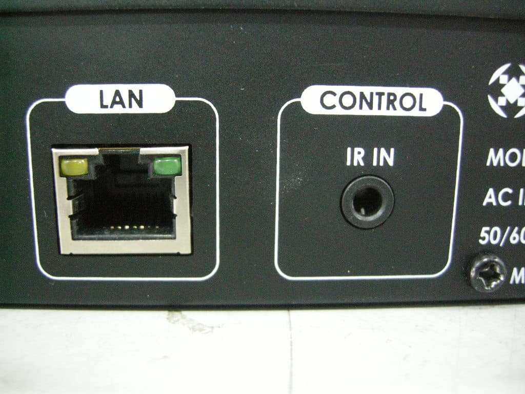
Click to zoom
Application Details
- Equipment Class
- JBP - Part 15 Class B Computing Device Peripheral
- Date of Grant
- Mar 03, 2011
- Application Purpose
- Original Equipment
- Date of Application
- Mar 02, 2011
- Equipment Note
- Single-Zone Amplifier
- Company
- Ohsung Electronics Co., Ltd.
- Country
- South Korea
Documents & Files
Document Text
Text extracted from the exhibit documents filed with the FCC. Open a document above to read the original.
Users Manual
DMS-100 Owner's Manual DMS-100 Owner’s Manual ©2010 Universal Remote Control, Inc. The information in this manual is copyright protected. No part of this manual may be copied or reproduced in any form without prior written consent from Universal Remote Control, Inc. UNIVERSAL REMOTE CONTROL, INC. SHALL NOT BE LIABLE FOR OPER- ATIONAL, TECHNICAL OR EDITORIAL ERRORS/OMISSIONS MADE IN THIS MANUAL. The information in this manual may be subject to change without prior notice. URC - Control the Experience is a registered trademark of Universal Remote Control, Inc. All other brand or product names are trademarks or registered trademarks of their respective companies or organizations. Universal Remote Control,Inc. 500 Mamaroneck Avenue, Harrison, NY 10528 Phone: (914) 835-4484 Fax: (914) 835-4532 Congratulations!2 Features and Benefits3 Parts Guide3 Front Panel Description4 System Features5 Rear Panel Description6 Federal Communication Commission Interference Statement 10 USA Limited Warranty Statement11 Specifications13 System Configuration for Internal LAN Network14 Europe Certificate Of Conformity15 TABLEOFCONTENTS Page 1 Page 2 DMS-100 SINGLE ZONEAMPLIFIER Congratulations! You’ve purchased the finest music distribution system available today. The DMS-100 is a native to the network, CD quality digital music distribution system with an available range of keypads and remote controls that not only fully control your music but control all of your other audio video components. The DMS-100 distributes music to your speakers and other DMS components in the system. This makes your system scalable, and easy to add additional rooms at any time in the future. All you need is a DMS amplifier connected to the network to make any room a new DMS Music Room. The DMS-100 is designed for professional installation only. Your installer will help you select the right user interface for every room of your installation. You’ll have a choice of Total Control in- wall keypads and remote controls. If you have questions, call your installer: Company: Installer Name: Contact #: Email address: The customer service center is also available for any questions you may have. Contact us at: 1-914-835-4484 or email us at: [email protected] Page 3 DMS-100 SINGLEZONEAMPLIFIER Features and Benefits • One audio input streams to other Total Control amplifiers. • Preamp output for connection to local amplifier. • Scalable solution; install as an additional zone with a DMS-1200 system, or install multiple DMS-100s to create customized multi-zone system. • 50 Watts per channel amplifier for speakers. • Can be programmed off premises via the internet and MRX-10. Parts Guide The DMS-100 Single Zone Amplifier includes: 1 - DMS-100 Single Zone Amplifier1 - Power Cord 1 - Ethernet Cable1 - Installation Manual Page 4 DMS-100 SINGLEZONEAMPLIFIER Front Panel Description Power and LAN LEDs LEDs indicate that the DMS-100 is connected to power and to the local area network. Automatic Power Off The DMS-100 is powered off and is in an automatic stand by state when no zones are active. Reset Button The front panel reset button offers the end user a quick way to reconnect the DMS-100 to the local area network. Page 5 DMS-100 SINGLE ZONEAMPLIFIER System Features Pristine Audio Quality Unlike other digital music systems, the DMS system streams all music uncompressed at pure CD quality levels. You enjoy all the detail of your original source. Room Linking Any room can be linked with any other room to listen to the same source. This makes it easy for you to entertain by simply linking all the rooms your guests will be in and controlling the music from any remote or keypad. Reliability The DMS-100 is engineered first and foremost for reliability. It offers extensive internal protection against failure and is manufac- tured in our ISO 9000 certified factory with the utmost attention to quality control at every stage of manufacturing, from parts procure- ment to final assembly. Page 6 DMS-100 SINGLEZONEAMPLIFIER Rear Panel Description 110V-220V Power Connection The IEC power socket enables either UL/CSA approved 110V power cords or CE approved 220V power cables to be used with the DMS-100. The internal power supply automatically switches from 110V to 240V. Network Connection A 10/100 LAN connection ensures that the DMS-100 will receive all network streams from other DMS or SNP sources. IR In for 1-Way RF Remotes and Base Stations When connected to a URC RF base station, a one-way URC remote control can be programmed to control a zone. Page 7 DMS-100 SINGLE ZONEAMPLIFIER System Features Analog Audio Input Connect a music source to the DMS-100 to listen locally to an AV receiver. Preamp Zone The preamp zone enables use of external power amplifiers for a room with a need for more or less power than 50 watts per channel. Speakers The DMS-100 internal amplifier powers a pair of 8 ohm speakers with 50 watts per speaker. The speakers can deliver output from any DMS source. Page 8 Important Safety Instructions This unit shall be connected to a mains socket outlet with a protective grounded connection or equivalent. CAUTION: To completely disconnect this product from the mains, disconnect the plug from the wall socket outlet. The mains plug is used to completely interrupt the power supply to the unit and must be within easy access by the user. CAUTION: These servicing instructions are for use by qualified service personnel only. To reduce the risk of electric shock, do not perform any servicing other than that contained in the operating instructions unless you are qualified to do so or equivalent. IMPORTANTS AFETY INSTRUCTIONS Page 9 IMPORTANTS AFETY INSTRUCTIONS Important Safety Instructions 1. Read these instructions. 2. Keep these instructions. 3. Heed all warnings. 4. Follow all instructions. 5. In the event of malfunction, un plug lmmediately. 6. Do not use this apparatus near water. 7. Clean only with dry cloth. 8. Do not block any ventilation op…
Text truncated - open the document above for the full version.
Cover Letter(s)
OHSUNG Electronics co. ltd. Date: December, 22, 2010 Federal Communications Commission 7435 Oakland Mills Road Columbia MD 21046 c.c. Compliance Certification Services Certification Division 47173 Benicia Street Fremont, CA 94538, USA To whom it may concern: I, the undersigned, hereby authorize Jin-Mo Yang, Engineering Manager of ESTECH Co., Ltd. and hereafter referred to as ESTECH, to act on our behalf in all manners relating to application for equipment authorization, including signing of all documents relating to these matters. Any and all acts carried out by Jin-Mo Yang, Engineering Manager of ESTECH Co. Ltd. on our behalf shall have the same effect as acts of our own. I, the undersigned, hereby certify that we are not subject to a denial of federal benefits, that includes FCC benefits, pursuant to Section 5301 of the Anti-Drug Abuse Act of 1988, 21 U.S.C. 853(a). In authorizing ESTECH as our agent, we still recognize that we are responsible to: a) comply with the relevant provisions of the certification program; b) make all necessary arrangements for the conduct of the evaluation, including provision for examining documentation and access to all areas, records (including internal audit reports) and personnel for the purposes of evaluation (e.g. testing, inspection, assessment, surveillance, reassessment) and resolution of complaints; c) make claims regarding certification only in respect of the scope for which certification has been granted; d) do not use our product certification in such a manner as to bring the Certification Division into disrepute and not make any statement regarding our product certification which the Certification Division may consider misleading or unauthorized;
External Photos
FRONT REAR PORT 1 PORT 2
ID Label/Location Info
OHSUNG ELECTRONICS CO.LTD Single-Zone Amplifier MODEL : DMS-100 FCC ID : OZ5URCDMS100 This device complies with part 15 or rhe FCC Rules. Operation is subject to the dollowing two conditions : (1) This device may not cause harmful interference, and (2) this device must accept ant interference received, including interference that may cause undesired o peration.
Internal Photos
1. Main 1.1 Front 1.2 Rear 2. AUDIO BOARD 2.1 Front 2.2 Rear 3. SMPS BOARD 3.1 Front 3.3 Rear 4. SWITCH BOARD 4.1 Front 4.2 Rear 5. LED BOARD 5.1 FRONT 5.2 Rear
Test Report
Test Report for FCC Company name Address Telephone Product name Model No. Serial No. Test date Testing location Standard □ Class A ■ Class B Test resultOK □ Class A ■ Class B Test resultOK Tested by Reviewed by Abbreviation * Note - This test report is not permitted to copy partly without our permission - This test result is dependent on only equipment to be used - This test result based on a single evaluation of one sample of the above mentioned FCC ID: OZ5URCDMS100 OK, Pass = Complied, Fail = Failed, N/A = not applicable OHSUNG ELECTRONICS CO.LTD 181 Gongdan-dong, Gumi-si, Gyeongsangbuk-Do, Korea 82-54-461-3647 Measurement facility registration number Senior Engineer J.H.KIM Engineering Manager J.M.Yang 94696 (Signature) (Signature) Date of issue ESTECH. Co., Ltd. 97-1 Hoiuk-Ri Majang-Myon, Icheon-city, KyungKi-Do, Korea Test item ■ Conducted Emission ■ Radiated Emission FCC PART 15 20 , ANSI C 63.4 2003 2011-01-06 DMS-100 NONE OHSUNG ELECTRONICS CO.LTD KOREA Report Number : ESTF151102-006 , Web : www. estech. co. kr Page 1 of 14 Report NumberESTF151102-006 Manufacturer Country of origin Applicant Product 22-Feb-11 Single-Zone Amplifier EST-QP-20-01(0)-(F15) 3 4 5 6 8 8 8 9 10 10 10 11 7. Photogra phs of test setup................................................................................. 12 7.1 Setu p for Radiated Test : above 30 MHz......................................................12 7.2 Setu p for Conducted Test : 0.15 MHz ~ 30 MHz..........................................13 8. Photogra phs of EUT..........................................................................................14 Appendix 1. Spectial diagram 6. Measurement of conducted emission ............................................................ 6.1 Measurement e quipment ........................................................................... 6.2 Environmental conditions ........................................................................... 6.3 Test data ................................................................................................ Report Number : ESTF151102-006 , Web : www. estech. co. kr Page 2 of 14 5. Measurement of radiated emission ............................................................... 5.1 Measurement e quipment ........................................................................... Contents 1. Laboratory Information ................................................................................. 2. Description of EUT ....................................................................................... 3. Test Standards ............................................................................................. 4. Measurement condition ................................................................................. 5.2 Environmental conditions ........................................................................ 5.3 Test data ............................................................................................. ... EST-QP-20-01(0)-(F15) 1. Laboratory Information 1.1 General 1.2 Test Lab. Head Office : Rm 1015, World Venture Center II, 426-5, Gasan-dong, Geumcheon-gu, Seoul, Korea (Safety & Telecom. Test Lab) EMC Test Lab : 58-1 Osan-Ri, GaNam-Myon, YeoJoo-Gun, KyungKi-Do, Korea 97-1 Hoiuk-Ri Majang-Myon, Icheon-city, KyungKi-Do, Korea 1.3 Official Qualification(s) KCC : Granted Accreditation from Ministry of Information & Communication for EMC, Safety and Telecommunication KOLAS : Accredited Lab By Korea Laboratory Accreditation Schema base on CENELEC requirements FCC : Filed Laboratory at Federal Communications Commission VCCI : Granted Accreditation from Voluntary Control Council for Interference from ITE This EUT (Equipment Under Test) has been shown to be capable of compliance with the applicable technical standards and is tested in accordance with the measurement procedures as indicated in this report. ESTECH Lab attests to accuracy of test data. All measurement reported herein were performed by ESTECH Co., Ltd. ESTECH Lab assume full responsibility for the completeness of these measurements and vouch for the qualifications of all persons taking them. Report Number : ESTF151102-006 , Web : www. estech. co. kr Page 3 of 14 Corporation Name : ESTECH Co. Ltd EST-QP-20-01(0)-(F15) 2. Description of EUT 2.1 Summary of Equipment Under Test Product Name : Model Number : DMS-100 Serial Number : Manufacturer : Country of origin : Rating : Receipt Date : X-tal lists: 2.2 General descriptions of EUT Report Number : ESTF151102-006 , Web : www. estech. co. kr Page 4 of 14 Single-Zone Amplifier NONE OHSUNG ELECTRONICS CO.LTD KOREA (100 ~ 245) Va.c., 2 A max., (50 ~ 60) Hz 22-Dec-10 18.432 MHz, 25 MHz, 32.768 kHz, 11.2986 MHz, 24.576 MHz EST-QP-20-01(0)-(F15) 3. Test Standards Test Standard : FCC PART 15 (2010) Test Method : ANSI C 63.4 (2003) This standard sets forth uniform methods of measurement of radio-frequency (RF) signals and noise emitted from both unintentional and intentional emitters of RF energy in the frequency range 9 kHz to 40 GHz. Methods for the measurement of radiated and AC power-line conducted radio noise are covered and may be applied to any such equipment unless otherwise specified by individual equipment requirements. These methods cover measurement of certain decides that deliberately radiate energy, such as intentional emitters, but does not cover licensed transmitters. This standard is not intended for certification/approval of avionic equipment or for industrial, scientific, and medical (ISM) equipment These method apply to the measurement of individual units or systems comprised of multiple units This Standard sets out the regulations under which an intentional, unintentional, or incidental radiator may be operated without an individual license. It also contains the technical specifications, administrative requirements and other conditions relating to the marketing of Part 15 devices. Report Number : ESTF151102-006 , Web : www.…
Text truncated - open the document above for the full version.
Test Setup Photos
TEST SETUP PHOTO 1. Conducted Emission setup photo 1.1. Front 1.2. Rear 2. Radiated Emission setup photo 2.1 Front 2.2. Rear
Contact Information
Applicant
Hak-Ki Kim(General Manager)
Test Firm
ESTECH Co., Ltd.Yang Jinmo
Technical Specifications
| # | Rule Parts | Frequency Range | Power Output |
|---|---|---|---|
| 1 | 15B | - | - |
Other Applications from Ohsung Electronics Co., Ltd.
OZ5PSRMT
Jan 13, 2026RF4CE RCU
Equipment Class
DTS - Digital Transmission SystemOZ5G32
Dec 29, 2025Remote Controller
Equipment Class
DTS - Digital Transmission SystemOZ5PSEMR
Dec 19, 2025RF Module
Equipment Class
DTS - Digital Transmission SystemOZ5G22
Dec 16, 2025Remote Controller
Equipment Class
DTS - Digital Transmission SystemOZ5G12
Dec 16, 2025Remote Controller
Equipment Class
DTS - Digital Transmission System