OZ5URCMRF250RF Receiver
Ohsung Electronics Co., Ltd.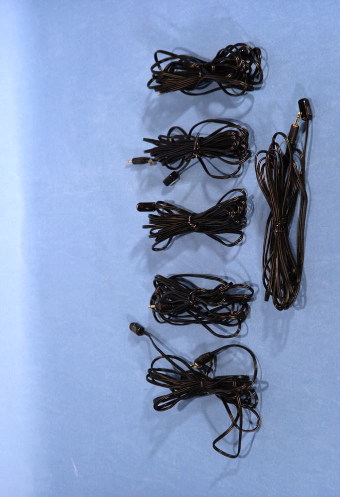
Click to zoom
Application Details
- Equipment Class
- CRR - Superregenerative Receiver
- Date of Grant
- Mar 04, 2004
- Application Purpose
- Original Equipment
- Date of Application
- Mar 04, 2004
- Equipment Note
- RF Receiver
- Frequency Range
- 418.00000000 - 418.00000000
- Company
- Ohsung Electronics Co., Ltd.
- Country
- South Korea
Documents & Files
Document Text
Text extracted from the exhibit documents filed with the FCC. Open a document above to read the original.
Users Manual
Multi-Room “No-Pointing” RF Control of Audio/Video Components MRF-250 INSTALLATION MANUAL MRF-250 Installation Manual © 2004 Universal Remote Control, Inc. The information in this manual is copyright protected. No part of this manual may be copied or reproduced in any form without prior written consent from Universal Remote Control, Inc. UNIVERSAL REMOTE CONTROL, INC. SHALL NOT BE LIABLE FOR OPERATIONAL,TECHNI- CAL OR EDITORIAL ERRORS/OMISSIONS MADE IN THIS MANUAL. The information in this manual may be subject to change without prior notice. Home Theater Master is a registered trademark of Universal Remote Control, Inc. Entertainment Made Simple is a trademark of Universal Remote Control, Inc. All other brand or product names are trademarks or registered trademarks of their respective companies or organizations. 500 Mamaroneck Avenue, Harrison, NY 10528 Phone: (914) 835-4484 Fax: (914) 835-4532 TT AABBLLEE OO FF CC OONNTTEENNTTSS Introduction1 Features and Benefits2 Parts Guide2 Front Panel3 Mounting Plate3 Power LED3 Status LED3 Front Blaster3 Rear Panel4 Flashers4 Power Supply4 Bottom Panel4 Receiver ID#4 A Standard MRF-250 System5 Standard Installation — Step by Step5 Front Blaster Overload7 Disabling the Front Blaster - Step by Step7 Controlling An Array of Identical TV’s8 Identical Components - Step by Step8 Programming For Multiple Equipment Locations11 Frequently Asked Questions12 Specifications12 PPaaggee 11 MMRRFF--225500 BB AASSEE SS TTAATTIIOONN Introduction The combination of the MX-3000 with it’s companion MRF-250 base station will enable you to place your audio/video components out of sight behind closed doors and/or in another room of your house. The MX-3000 sends radio signals to the MRF-250 throughout your house (50-100’ away, indoors or outdoors). The MRF-250 converts your commands to the infrared signals that control your A/V components. 3. Self-adhesive “Flashers” affix to the Infrared sensors on the front panels of your components. The Flashers relay commands to components out of sight of the MRF-250’s Front Blaster. The flashers plug in to the MRF-250’s rear flasher line outputs via their 10 foot cables. 2.The MRF-250’s built-in Front Blaster sends commands to components in the same cabinet space as the MRF-250. 1.The MX-30000 remote con- trol sends radio waves in every direction, so you don’t have to point the remote any- more! PPaaggee 22 MMRRFF--225500 BB AASSEE SS TTAATTIIOONN Features and Benefits NNoo MMoorree PPooiinnttiinngg -- RRaaddiioo WWaavveess PPeenneettrraattee WWaallllss,, DDoooorrss aanndd FFlloooorrss The MRF-250 receives the RF signals of the MX-3000 remote control from any direction. You no longer need to point the remote control at any of your A/V components. You can also place the components distracting blinking lights and displays behind closed doors and/or in another room! RReelliiaabbllee CCoonnttrrooll TThhrroouugghhoouutt YYoouurr HHoouussee The MRF-250 receives RF signals from your MX-3000 from within a radius of 50 to 100 feet enabling you to control out of sight audio/video components behind walls and closed doors. Range depends on the structure of your home and the amount of interference generated by computers, microprocessors and other devices within and nearby your home. UUpp TToo SSiixxtteeeenn EEqquuiippmmeenntt LLooccaattiioonnss CCoonnttrroolllleedd FFrroomm AAnnyy MMXX--33000000 Each MX-3000 can be programmed to operate equipment placed throughout the house, by installing an MRF-250 base station at each location. Each MRF- 250 is assigned one of 16 unique ID#’s. In operation it’s simple: when you select a device located in the Den, the MX-3000 only talks to the MRF-250 in the Den. When you select a device located in the Family Room, the MX-3000 only talks to it! NNoo PPooiinnttiinngg RReemmoottee CCoonnttrroollss IInn EEvveerryy RRoooomm You can opt to control a multi-room or multi-zone system via RF remote con- trol by placing an MX-3000 in each room of your home. CCoonnttrrooll AA MMeeddiiaa RRoooomm AArrrraayy ooff IIddeennttiiccaall TTVV’’ss The MRF-250’s unique assignable IR flashers enable your installation to control up to six identical TV’s. The intelligent routing of the MRF-250 will send your commands only to the TV you select on your MX-3000. The other identical TV’s will not receive commands. Of course, if your system utilizes identical satellite receivers, cable boxes, VCR’s or disc changers you can utilize IR rout- ing just as easily for them. If you have more than six identical components, up to 16 additional MRF-250’s can be installed to control them (thus allowing up to 96 identical components in one house). Parts Guide The MRF-250 RF Base Station includes: 1 - MRF-250 Receiver with integrated antenna 1 - Mounting Plate for wall mounting the MRF-250 4 - Screws for wall mounting the mounting plate 1 - 9V-300mA Power Supply 6 - Flashers with 10 foot plug in cables. PPaaggee 33 MMRRFF--225500 BB AASSEE SS TTAATTIIOONN The MRF-250’s slots enable the Mounting Plate’s matching guides to slide and “snap” into place for mounting on the wall. Using the four enclosed screws, you can choose to fix the mounting plate to a wall or the back of your component cabinet. Front Blaster sends Infrared com- mands to all A/V components in the same cabinet space. The MRF-250 Mounting Plate MRF-250 Details Red POWERLED lights when the MRF-250’s power supply is plugged into an active AC outlet. Red STATUSLED lights when the MRF-250 receives an RF signal from the MX-3000. PPaaggee 44 MMRRFF--225500 BB AASSEE SS TTAATTIIOONN Six Plug-In Flashers are supplied with 10 foot cables and six extra self-adhesive pads (in case a flash- er has to be repositioned). Bottom panel Dial sets the Receiver ID# when more than one MRF-250 receiver is used. Included 9V power supply plugs into the MRF-250’s power connector. Integrated Antenna swings in any direction to optimize RF recep- tion and range. Six Rear Flasher Line Output Jacks connect flashers for…
Text truncated - open the document above for the full version.
Attestation Statements
, 82 MAR 'WB 15:21 STD ENG 839-6549 .4 OHSUNG ELECTRONICS Cow, LTD. June 9, 2003 I)eu Sir, I. D. J, Jung I Managter OHSUNG ELECTRNB Co., Ltd
Block Diagram
파형정형 DATA OUT LPF RF AMP ANT DESCRIPTOIN 12 345 No Q'TY MODEL NANE Rx Block Diagram CHECK ED MATERLAL DATA PART NAME KOREA I.S Co., Ltd DESIGN ED CHECK ED APPRO VAL DRAWN 2003 12. 02 AF AMP Sampling
Cover Letter(s)
March 5, 2004 Federal Communications Commission Authorization & Evaluation Division Equipment Authorization Branch 7435 Oakland Mills Road Columbia, MD 21046 SUBJECT: OHSUNG Electronics Co., Ltd. FCC ID: OZ5URCMRF250 Gentlemen: Submitted herewith, on behalf of OHSUNG Electronics Co. Ltd., is an application for Part 15 class B certification of the RF Receiver. Attached are the applicant’s authorization letter, FCC ID label and location, Test Setup Photos, External & Internal Photographs, Block/Schematics Diagram(s), Measurement Report, and Users Manual. This statement, from § 15.21, “Changes or modifications not expressly approved by the party responsible for compliance could void the user’s authority to operate the equipment.” will be included with manual. Should you have any questions or comments concerning the above, please contact the undersigned. cc: OHSUNG Electronics Co., Ltd.
External Photos
FCC ID: OZ5URCMRF250 EUT Photographs © 2004 PCTEST Lab. OHSUNG RF Receiver Model: MRF-250 FCC ID: OZ5URCMRF250 EUT Photographs © 2004 PCTEST Lab. OHSUNG RF Receiver Model: MRF-250 FCC ID: OZ5URCMRF250 EUT Photographs © 2004 PCTEST Lab. OHSUNG RF Receiver Model: MRF-250 FCC ID: OZ5URCMRF250 EUT Photographs © 2004 PCTEST Lab. OHSUNG RF Receiver Model: MRF-250 FCC ID: OZ5URCMRF250 EUT Photographs © 2004 PCTEST Lab. OHSUNG RF Receiver Model: MRF-250 FCC ID: OZ5URCMRF250 EUT Photographs © 2004 PCTEST Lab. OHSUNG RF Receiver Model: MRF-250
ID Label/Location Info
CONFIDENTIAL MRF-250 FCC ID : OZ5URCMRF250 FCC ID : OZ5URCMRF250 SCALE : 2 / 1 MADE IN KOREA MADE IN KOREA
Internal Photos
FCC ID: OZ5URCMRF250 EUT Photographs © 2004 PCTEST Lab. OHSUNG RF Receiver Model: MRF-250 FCC ID: OZ5URCMRF250 EUT Photographs © 2004 PCTEST Lab. OHSUNG RF Receiver Model: MRF-250 FCC ID: OZ5URCMRF250 EUT Photographs © 2004 PCTEST Lab. OHSUNG RF Receiver Model: MRF-250 FCC ID: OZ5URCMRF250 EUT Photographs © 2004 PCTEST Lab. OHSUNG RF Receiver Model: MRF-250 FCC ID: OZ5URCMRF250 EUT Photographs © 2004 PCTEST Lab. OHSUNG RF Receiver Model: MRF-250
Operational Description
“ ” “ ” “ ” “ ” “ ” “ ” “ ” “ ” “ ” “ ” “ ” “ ” ” “ ”
Test Report
© 2004 PCTEST Engineering Lab., Inc. PCTEST Engineering Laboratory, Inc. 66606660--B Dobbin Road B Dobbin Road •• Columbia, MD 21045 Columbia, MD 21045 •• U.S.A. U.S.A. TEL (410) 290TEL (410) 290--6652 6652 •• FAX (410) 290 FAX (410) 290--66546654 http://www.pctestlab.comhttp://www.pctestlab.com CERTIFICATE OF COMPLIANCE Manufacturer: OHSUNG ELECTRONICS CO., LTD. Dates of Tests: March 5, 2004 #181 Dong Dan-Dong Test Report S/N: B.240225144.OZ5 Gu-Mi Kyung Buk, Korea Test Site: PCTEST Lab, MD U.S.A. FCC ID: OZ5URCMRF250 APPLICANT OHSUNG ELECTRONICS CO., LTD. FCC Rule Part(s): FCC Part 15 Subpart B - Receiver FCC Classification: Superregenerative Receiver (CRR) Equipment EUT Type: RF Receiver Trade Name: HOME THEATER MASTER Rx Frequency: 418 MHz The device bearing the trade name and model specified above has been shown to comply with the applicable technical standards as indicated in the measurement report and has been tested in accordance with the measurement procedures specified is ANSI C63.4-1992. (See Test Report if any modifications were made for compliance). These measurements were performed with no deviation from the standards. I attest to the accuracy of data. All measurements reported herein were performed by me or were made under my supervision and are correct to the best of my knowledge and belief. I assume full responsibility for the completeness of these measurements and vouch for the qualifications of all persons taking them. CE: This device has shown compliance with the conducted emissions limits in 15.107, 15.207, or 18.307 adopted under FCC 02- 157 (ET Docket 98-80). The device may be marketed after July 11, 2005, and is not affected by the 15.37(j) or 18.123 transition provisions. NVLAP accreditation does not constitute any product endorsement by NVLAP or any agency of the United States Government PCTEST certifies that no party to this application has been denied the FCC benefits pursuant to Section 5301 of the Anti-Drug Abuse Act of 1988, 21 U.S.C. 862. 230114055.OZ5 PCTEST PT. 15. REPORT Measurement Report Reviewed By: Quality Manager Test Report S/N: B. 240225144.OZ5 Test Dates: March 5, 2004 EUT Type: RF Receiver FCC ID: OZ5URCMRF250 Page i of i TABLE OF CONTENTS ATTACHMENT A: COVER LETTER(S) ATTACHMENT B: ATTESTATION STATEMENT(S) ATTACHMENT C: TEST REPORT SCOPE 1 INTRODUCTION (SITE DESCRIPTION) 2 PRODUCTION INFORMATION 3 DESCRIPTION OF TESTS (CONDUCTED) 4 DESCRIPTION OF TESTS (RADIATED) 5 TEST EQUIPMENT 6 TEST DATA (CONDUCTED) 7 TEST DATA (RADIATED) 8 SAMPLE CALCULATIONS 9 ACCURACY OF MEASUREMENT 10 LIST OF TEST EQUIPMENT 11 TEST SOFTWARE USED 12 CONCLUSION 13 ATTACHMENT D: TEST PLOTS ATTACHMENT E: FCC ID LABEL & LOCATION ATTACHMENT F: BLOCK DIAGRAM ATTACHMENT G: SCHEMATICS ATTACHMENT H: TEST SETUP PHOTOGRAPHS ATTACHMENT I: EXTERNAL PHOTOS ATTACHMENT J: INTERNAL PHOTOS ATTACHMENT K: USERS MANUAL PCTEST PT. 15 REPORT Measurement Report Reviewed By: Quality Manager Test Report S/N: B.240225144.OZ5 Test Dates: March 5, 2004 EUT Type: RF Receiver FCC ID: OZ5URCMRF250 Page 1 of 13 MEASUREMENT REPORT Scope - Measurement and determination of electromagnetic emissions (EME) of radio frequency devices including intentional and/or unintentional radiators for compliance with the technical rules and regulations of the Federal Communications Commission. Company Name: OHSUNG ELECTRONICS CO., LTD. Address: #181 Dong Dan-Dong Gu-Mi Kyung Buk, Korea • Trade Name(s): HOME THEATER MASTER • FCC ID: OZ5URCMRF250 • EUT Type: RF Receiver • FCC Rule Part(s): FCC Part 15 Subpart B - Receiver • Classification: Superregenerative Receiver (CRR) • Test Procedure(s): ANSI C63.4 (1992) / EN55022: 1998 (CISPR 22) w/ A1 (2001) • Dates of Tests: March 5, 2004 • Place of Tests: PCTEST Lab, Columbia, MD U.S.A. • Test Report S/N: B.240225144.OZ5 221218032.A3L PCTEST PT. 15 REPORT Measurement Report Reviewed By: Quality Manager Test Report S/N: B.240225144.OZ5 Test Dates: March 5, 2004 EUT Type: RF Receiver FCC ID: OZ5URCMRF250 Page 2 of 13 1.1 INTRODUCTION The measurement procedure described in American National Standard for Methods of Measurement of Radio- Noise Emissions from Low-Voltage Electrical and Electronic Equipment in the Range of 9kHz to 40GHz (ANSI C63.4-1992) was used in determining radiated and conducted emissions emanating from OHSUNG RF Receiver FCC ID: OZ5URCMRF250. These measurement tests were conducted at PCTEST Engineering Laboratory, Inc. facility in New Concept Business Park, Guilford Industrial Park, Columbia, Maryland. The site address is 6660-B Dobbin Road, Columbia, MD 21045. The test site is one of the highest points in the Columbia area with an elevation of 390 feet above mean sea level. The site coordinates are 39° 11'15" N latitude and 76° 49'38" W longitude. The facility is 1.5 miles North of the FCC laboratory, and the ambient signal and ambient signal strength are approximately equal to those of the FCC laboratory. There are no FM or TV transmitters within 15 miles of the site. The detailed description of the measurement facility was found to be in compliance with the requirements of § 2.948 according to ANSI C63.4 on October 19, 1992. 1.2 PCTEST Location The map at right shows the location of the PCTEST Lab, its proximity to the FCC Lab, the Columbia vicinity area, the Baltimore-Washington International (BWI) airport, and the city of Baltimore, and the Washington, D.C. area. (see Figure1). Figure 1. Map of the Greater Baltimore and Metropolitan Washington, D.C. area. PCTEST PT. 15 REPORT Measurement Report Reviewed By: Quality Manager Test Report S/N: B.240225144.OZ5 Test Dates: March 5, 2004 EUT Type: RF Receiver FCC ID: OZ5URCMRF250 Page 3 of 13 2.1 Product Information 2.2 Equipment Description The Equipment Under Test (EUT) is the OHSUNG RF Receiver. Frequency Range: 418 MHz Antenna: Omni directional Power: DC 9V 300mA IR Flasher Line Outputs: 2.5mm Mono Mini Jack Size: 5 1/8” x 3.5” x 1.25” (4.5” antenna up) 2.3 EMI Suppression Device(s) EMI suppression devi…
Text truncated - open the document above for the full version.
Test Setup Photos
FCC ID: OZ5URCMRF250 EUT Photographs © 2004 PCTEST Lab. OHSUNG RF Receiver Model: MRF-250 FCC ID: OZ5URCMRF250 EUT Photographs © 2004 PCTEST Lab. OHSUNG RF Receiver Model: MRF-250 FCC ID: OZ5URCMRF250 EUT Photographs © 2004 PCTEST Lab. OHSUNG RF Receiver Model: MRF-250 FCC ID: OZ5URCMRF250 EUT Photographs © 2004 PCTEST Lab. OHSUNG RF Receiver Model: MRF-250
Contact Information
Applicant
Hak-Ki Kim(General Manager)
Technical Contact
PCTEST Engineering Lab., Inc.Randy Ortanez
[email protected]410-290-6652
6660-B Dobbin Road · Columbia, Maryland · United States
Test Firm
PCTEST Engineering Laboratory, Inc.Randy Ortanez
Technical Specifications
| # | Rule Parts | Frequency Range | Power Output |
|---|---|---|---|
| 1 | 15B | 418 MHz - 418 MHz | - |
Other Applications from Ohsung Electronics Co., Ltd.
OZ5PSRMT
Jan 13, 2026RF4CE RCU
Equipment Class
DTS - Digital Transmission SystemOZ5G32
Dec 29, 2025Remote Controller
Equipment Class
DTS - Digital Transmission SystemOZ5PSEMR
Dec 19, 2025RF Module
Equipment Class
DTS - Digital Transmission SystemOZ5G22
Dec 16, 2025Remote Controller
Equipment Class
DTS - Digital Transmission SystemOZ5G12
Dec 16, 2025Remote Controller
Equipment Class
DTS - Digital Transmission System