OZ5URCMRF250CRF BASE STATION
Ohsung Electronics Co., Ltd.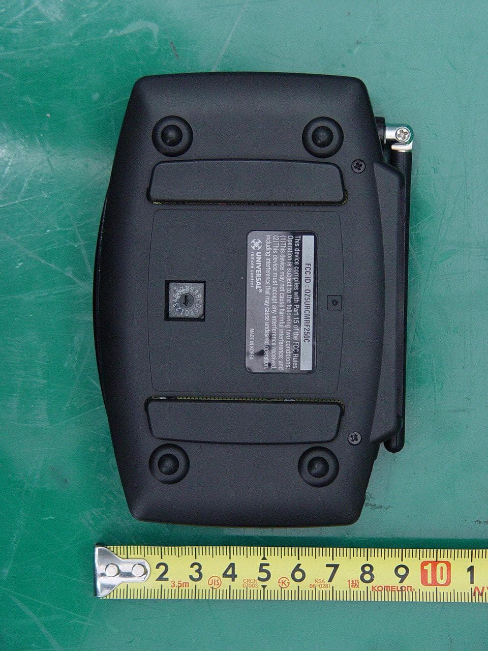
Click to zoom
Application Details
- Equipment Class
- CYY - Communications Receiver used w/Pt 15 Transmitter
- Date of Grant
- Apr 10, 2011
- Application Purpose
- Original Equipment
- Date of Application
- Apr 10, 2011
- Equipment Note
- RF BASE STATION
- Frequency Range
- 418.00000000 - 418.00000000
- Company
- Ohsung Electronics Co., Ltd.
- Country
- South Korea
Documents & Files
Document Text
Text extracted from the exhibit documents filed with the FCC. Open a document above to read the original.
Users Manual
Order Number : GETEC-C1-11-074 FCC Part 15 subpart B Test Report Number : GETEC-E3-11-024 Page 1 / 1 EUT Type: RF BASE STATION FCC ID.: OZ5URCMRF250C APPENDIX H : USER’S MANUAL Multi-Room “No-Pointing”RF Control of Cable Box/your Components MRF-250C INSTALLATION MANUAL 500 Mamaroneck Avenue, Harrison, NY 10528 Phone: (914) 835-4484 Fax: (914) 835-4532 MRF-250C Installation Manual ©2011 Universal Remote Control, Inc. The information in this manual is copyright protected. No part of this manual may be copied or reproduced in any form without prior written consent from Universal Remote Control, Inc. UNIVERSAL REMOTE CONTROL, INC. SHALL NOT BE LIABLE FOR OPERATIONAL, TECHNI- CAL OR EDITORIAL ERRORS/OMISSIONS MADE IN THIS MANUAL. The information in this manual may be subject to change without prior notice. Home Theater Master is a registered trademark of Universal Remote Control, Inc. Entertainment Made Simple is a trademark of Universal Remote Control, Inc. All other brand or product names are trademarks or registered trademarks of their respective companies or organizations. TABLEOFCONTENTS Introduction1 Features and Benefits2 Parts Guide2 MFS-250C Details3 A Standard MRF-250C System5 Front Blaster Overload6 RF Setup Method for remote6 Frequently Asked Questions6 USA Limited Warranty Statement7 Specifications8 Federal Communication Commission Interference Statement9 Page 1 MRF-250C BASESTATION Introduction The combination of the UR5L-9000LRF with it’s companion MRF-250C base station will enable you to place your Cable Box/your components out of sight behind closed doors or in another room of your house. The MRF-250C converts commands to infrared signals that control you AV components. This allows the UR5L-9000LRF to send radio signals throughout your house whether you be indoors, outdoors, or even up to 100’ away. 1. The UR5L-9000LRF remote control sends radio waves in every direction, so you don’t have to point the remote at the device anymore! 2. The MRF-250C’s built-in Front Blaster sends commands to components in the same cabinet space as the MRF-250C. 3. Self-adhesive “Flashers”affix to the Infrared sensors on the front panels of your components. The Flashers relay commands to components out of sight of the MRF-250C’s Front Blaster. The flashers plug in to the MRF-250C’s rear allowing the flasher line to output via their 10 foot cables. Page 2 MRF-250C BASESTATION Features and Benefits No More Pointing - Radio Waves Penetrate Walls, Doors and Floors The MRF-250C receives the RF signals of the UR5L-9000LRF remote control from any direction. You no longer need to point the remote control at any of your AV components. You can also place the components distracting blinking lights and displays behind closed doors or in another room! Reliable Control Throughout Your House The MRF-250C receives RF signals from your UR5L-9000LRF from within a radius of 50 to 100 feet enabling you to control out of sight cable boxes or components such at those behind walls or closed doors. Range depends on the structure of your home and the amount of interference generated by computers, microprocessors and other devices within and nearby your home. Control an Equipment Locations Controlled From Any UR5L-9000LRF Each UR5L-9000LRF can be programmed to operate equipment in another room, by installing an MRF-250C base station at each location. The MRF-250C is assigned one of 16 unique ID# s. In operation it is simple: when you select a device located in the den, the UR5L-9000LRF only signals to the MRF-250C in the den. No Pointing Remote Controls In Every Room You can opt to control a multi-room or multi-zone system via RF remote control by placing a UR5L-9000LRF in each room of your home. Parts Guide The MRF-250C RF Base Station includes: 1 - MRF-250C Receiver with integrated antenna 1 - Mounting Plate for wall mounting the MRF-250C 4 - Screws for wall mounting the mounting plate 1 - 9V-300mA Power Supply 6 - Flashers with 10 foot plug in cables. Page 3 MRF-250C BASESTATION MRF-250C Details Using the four enclosed screws, you can choose to fix the mounting plate to a wall or the back of your component cabinet. The MRF-250C’s slots enable the mounting plate‘s matching guides to slide and “snap”into place for quick and easy mounting on the wall. Front Blaster sends Infrared commands to all AV components in the same cabinet space. Red POWERLED Lights up when the MRF-250C’s power supply is plugged into an active AC outlet. Red S TATUSLED Lights up when the MRF-250C receives an RF signal from the UR5L-9000LRF. The MRF-250C Mounting Plate Page 4 MRF-250C BASESTATION Bottom panel Dial sets the Receiver ID# when more than one MRF-250C receiver is used. Included 9V power supply plugs into the MRF-250C’s power connector. Integrated Antenna swings in any direction to optimize RF recep- tion and range. Six Rear Flasher Line Output Jacks connect flashers for control of A/V components out of sight of the MRF- 250C’s Front Blaster. Six Plug-In Flashers are supplied with 10 foot cables and six extra self-adhesive pads in case a flasher has to be repositioned. A Standard MRF-250C System A standard system utilizes one UR5L-9000LRF and one MRF-250C to control an equipment location. Step 1 - Place the MRF-250C The MRF-250C should be placed so that the Front Blaster will control as many of the system’s AV components as possible. If you are connecting the outboard flashers to the rear Flasher outputs only, the MRF-250C may be concealed and mounted to the rear wall or back of the system cabinet. The mounting plate slides apart from the receiver, screws to the wall or cabinet with the enclosed screws, then the receiver is slid back into place. Step 2 - Connect the Power Supply and Insert the Batteries Connect the 9V power supply to an active UNSWITCHED AC outlet. The MRF- 250C must always be powered up to operate. The red P OWERLED should Light up. Insert the batteries in the UR5L-9000LRF remote control. Step 3 - Test the UR5L-9000LRF Ob…
Text truncated - open the document above for the full version.
Cover Letter(s)
2206 Ringwood Avenue San Jose, CA 95131 Tel: 408-526-1188 Fax: 408-526-1088 Email: [email protected] Project and Product Certification Representative Authorization Letter Revision History Reason for Amendment (current / obsolete) From To Approved Date Initial Release (current) 1.0 1.0 Nov-14-2006 Revised wording (current) 1.0 2.0 Sept–25-2007 SCS-F18: Project and Product Certification Representative Authorization Letter Page 1 of 2 Rev 2.0 OHSUNG ELECTRONICS CO., LTD #181 Gongdan-Dong, Gumi-Si,Gyeongsangbuk-Do, Korea Tel: +82-54-468-7282, Fax: +82-54-461-8368 April 11, 2011 To: SIEMIC, INC. 2206 Ringwood Avenue, San Jose, CA 95131 USA Dear Sir/Madam, Re: Project and Product Certification Representative Authorization Letter We, OHSUNG ELECTRONICS CO., LTD, hereby authorize SIEMIC, INC. to act as a Certification Body for certifying for the following project(s): Product Name: RF BASE STATION FCC ID: OZ5URCMRF250C We affirm that between SIEMIC and OHSUNG ELECTRONICS CO., LTD, any difference in understanding, including test plan, measurement methods, applicable standards and relevant procedures and processes have been resolved prior to commencement of testing activities. Sincerely, --------------------------------------------- Hak-Ki Kim, Q.C Manager OHSUNG ELECTRONICS CO.,LTD SCS-F18: Project and Product Certification Representative Authorization Letter Page 2 of 2 Rev 2.0
Cover Letter(s)
Confidentiality Request Letter Revision History Reason for Amendment (current / obsolete) From To Approved Date Initial Release (current) 1.0 1.0 Nov-14-2006 OHSUNG ELECTRONICS CO., LTD #181 Gongdan-Dong, Gumi-Si,Gyeongsangbuk-Do, Korea Tel: +82-54-468-7282, Fax: +82-54-461-8368 SCS-F19: Confidentiality Request Letter Rev 1.0 Nov 14, 2006 Federal Communications Commission Authorization and Evaluation Division April 11, 2011 Confidentiality Request regarding application for certification of FCC ID: OZ5URCMRF250C We hereby request confidential treatment of information accompanying this application as outlined below: Exhibit TypeFile Name URCMRF250C_BlkDia.pdf BLOCK DIAGRAM URCMRF250C_SchDia.pdf SCHEMETIC DIAGRAM URCMRF250C_OpeDes.pdf OPERATIONAL DESCRIPTION URCMRF250C_PrtLst.pdf PART LIST The above materials contain trade secrets and proprietary information not customarily released to the public. The public disclosure of these materials may be harmful to the applicant and provide unjustified benefits to its competitors. In addition to above mentioned documents, pursuant to Public DA 04-1705 of the Commission’s policy, in order to comply with the marketing regulations in 47 CFR 2.803 and the importation rules in 47 CFR 2.1204, while ensuring that business sensitive information remains confidential until the actual marketing of newly authorized devices. We are requesting the commission to grant short-term confidentiality request on the following Exhibit TypeFile Name URCMRF250C_Tsup.pdf TEST SET UP PHOTOS URCMRF250C_ExtPho.pdf EXTERNAL PHOTOGRAPHS URCMRF250C_IntPho.pdf INTERNAL PHOTOGRAPHS URCMRF250C_UseMan.pdf USER’S MANUAL The applicant understands that pursuant to Section 0.457 of the Rules, disclosure of this application and all accompanying documentation will not be made before the date of the Grant for this application. Sincerely, --------------------------------------------- Hak-Ki Kim, Q.C Manager OHSUNG ELECTRONICS CO.,LTD
External Photos
Order Number : GETEC-C1-11-074 FCC Part 15 subpart B Test Report Number : GETEC-E3-11-024 Page 1 / 7 EUT Type: RF BASE STATION FCC ID.: OZ5URCMRF25C APPENDIX F : EXTERNAL PHOTOGRAPHS Order Number : GETEC-C1-11-074 FCC Part 15 subpart B Test Report Number : GETEC-E3-11-024 Page 2 / 7 EUT Type: RF BASE STATION FCC ID.: OZ5URCMRF25C Order Number : GETEC-C1-11-074 FCC Part 15 subpart B Test Report Number : GETEC-E3-11-024 Page 3 / 7 EUT Type: RF BASE STATION FCC ID.: OZ5URCMRF25C Order Number : GETEC-C1-11-074 FCC Part 15 subpart B Test Report Number : GETEC-E3-11-024 Page 4 / 7 EUT Type: RF BASE STATION FCC ID.: OZ5URCMRF25C Order Number : GETEC-C1-11-074 FCC Part 15 subpart B Test Report Number : GETEC-E3-11-024 Page 5 / 7 EUT Type: RF BASE STATION FCC ID.: OZ5URCMRF25C Order Number : GETEC-C1-11-074 FCC Part 15 subpart B Test Report Number : GETEC-E3-11-024 Page 6 / 7 EUT Type: RF BASE STATION FCC ID.: OZ5URCMRF25C Order Number : GETEC-C1-11-074 FCC Part 15 subpart B Test Report Number : GETEC-E3-11-024 Page 7 / 7 EUT Type: RF BASE STATION FCC ID.: OZ5URCMRF25C
ID Label/Location Info
Order Number : GETEC-C1-11-074 FCC Part 15 subpart B Test Report Number : GETEC-E3-11-024 Page 1 / 2 EUT Type: RF BASE STATION FCC ID.: OZ5URCMRF250C APPENDIX B : ID SAMPLE LABEL & LOCATION Order Number : GETEC-C1-11-074 FCC Part 15 subpart B Test Report Number : GETEC-E3-11-024 Page 2 / 2 EUT Type: RF BASE STATION FCC ID.: OZ5URCMRF250C LABELLING REQUIREMENTS The label shown shall be permanently affixed at a conspicuous location on the device and be readily visible to the user at the time of purchase. ID Label ID Label Location of EUT ID Label
Internal Photos
Order Number : GETEC-C1-11-074 FCC Part 15 subpart B Test Report Number : GETEC-E3-11-024 Page 1 / 9 EUT Type: RF BASE STATION FCC ID.: OZ5URCMRF250C APPENDIX G : INTERNAL PHOTOGRAPHS Order Number : GETEC-C1-11-074 FCC Part 15 subpart B Test Report Number : GETEC-E3-11-024 Page 2 / 9 EUT Type: RF BASE STATION FCC ID.: OZ5URCMRF250C Order Number : GETEC-C1-11-074 FCC Part 15 subpart B Test Report Number : GETEC-E3-11-024 Page 3 / 9 EUT Type: RF BASE STATION FCC ID.: OZ5URCMRF250C Order Number : GETEC-C1-11-074 FCC Part 15 subpart B Test Report Number : GETEC-E3-11-024 Page 4 / 9 EUT Type: RF BASE STATION FCC ID.: OZ5URCMRF250C Order Number : GETEC-C1-11-074 FCC Part 15 subpart B Test Report Number : GETEC-E3-11-024 Page 5 / 9 EUT Type: RF BASE STATION FCC ID.: OZ5URCMRF250C Order Number : GETEC-C1-11-074 FCC Part 15 subpart B Test Report Number : GETEC-E3-11-024 Page 6 / 9 EUT Type: RF BASE STATION FCC ID.: OZ5URCMRF250C Order Number : GETEC-C1-11-074 FCC Part 15 subpart B Test Report Number : GETEC-E3-11-024 Page 7 / 9 EUT Type: RF BASE STATION FCC ID.: OZ5URCMRF250C Order Number : GETEC-C1-11-074 FCC Part 15 subpart B Test Report Number : GETEC-E3-11-024 Page 8 / 9 EUT Type: RF BASE STATION FCC ID.: OZ5URCMRF250C Order Number : GETEC-C1-11-074 FCC Part 15 subpart B Test Report Number : GETEC-E3-11-024 Page 9 / 9 EUT Type: RF BASE STATION FCC ID.: OZ5URCMRF250C
Test Report
nn~.많{¥gR£$GE Page 1 of 18 FCC EVALUATION REPORT FOR CERTIFICATION Date of Issue : April11, 2011 Order Number: GETEC-CI-11-074 Applicant : OHSUNG ELECTRONICS CO., LTD. #181 Gongdan-dong , Gumi-si, Gyeongbuk, Republic of Korea. AUn: Mr. Hak-Ki Kim / General Manager Test Report Number: GETEC-E3-11-024 Test Site: Gumi College EMC Center FCC Registration Number: (100749,443957) FCC ID. OZ5URCMRF250C Applicant: OHSUNG ELECTRONICS CO., LTD. Rule Part(s) : FCC Part 15 Subpart B Equipment Class : Communications Receiver used with Part 15 Transmitter (CYY) EUT Type : RF BASE STATION Type of Authority : Certification Model Name : MRF-250C Trade Name : UNIVERSAL remote control This equipment has been shown to be in compliance with the applicable technical standards as indicated in the measurement report and was tested in accordance with the measurement procedures specified in ANSI C63.4-2003 1 attest to the accuracy of data. All measurements reported herein were performed by me or were made under my supervision and are correct to the vest of my knowledge and belief. 1 assume ω” responsibility for the completeness of these measurements and vouch for the qualifications of all persons taking them. Tested by, S00η1ftιeη Soon-Hoon Jeong, Associate Engineer GUMI CoUege EMC center GETEC-QP- 28-007 (Rev.OO) Reviewed by, Jae-Hoon Jeonf(,Senior Engineer GUMI CoUege'EMC center 전자피센터 This test report only contains the result of a specific sample supplied for the examination. 1t is not allowed to copy this report even partly without the approval of EMC center Order Number : GETEC-C1-11-074 FCC Part 15 subpart C Test Report Number : GETEC-E3-11-024 Page 2 / 18 EUT Type: RF BASE STATION FCC ID.: OZ5URCMRF250C CONTENTS 1. GENERAL INFORMATION ................................................................................................................................ 3 2. INTRODUCTION ................................................................................................................................................. 4 3. PRODUCT INFORMATION ................................................................................................................................ 5 3.1 DESCRIPTION OF EUT ....................................................................................................................................... 5 3.2 SUPPORT EQUIPMENT / CABLES USED ................................................................................................................ 6 3.3 MODIFICATION ITEM(S) .................................................................................................................................... 6 4. DESCRIPTION OF TESTS .................................................................................................................................. 7 4.1 TEST CONDITION ............................................................................................................................................... 7 4.2 CONDUCTED EMISSION...................................................................................................................................... 8 4.3 RADIATED EMISSION ......................................................................................................................................... 9 5. CONDUCTED EMISSION ................................................................................................................................. 10 5.1 OPERATING ENVIRONMENT ............................................................................................................................. 10 5.2 TEST SET-UP .................................................................................................................................................... 10 5.3 MEASUREMENT UNCERTAINTY ........................................................................................................................ 10 5.4 LIMIT .............................................................................................................................................................. 11 5.5 TEST EQUIPMENT USED ................................................................................................................................... 11 5.6 TEST DATA FOR CONDUCTED EMISSION ........................................................................................................... 11 6. RADIATED EMISSION ...................................................................................................................................... 14 6.1 OPERATING ENVIRONMENT ............................................................................................................................. 14 6.2 TEST SET-UP .................................................................................................................................................... 14 6.3 MEASUREMENT UNCERTAINTY ........................................................................................................................ 14 6.4 LIMIT .............................................................................................................................................................. 15 6.5 TEST EQUIPMENT USED ................................................................................................................................... 15 6.6 TEST DATA FOR RADIATED EMISSION .............................................................................................................. 16 7. SAMPLE CALCULATIONS............................................................................................................................... 17 7.1 EXAMPLE 1 : .................................................................................................................................................... 17 7.2 EXAMPLE 2 : ..................................................................................................................................…
Text truncated - open the document above for the full version.
Test Setup Photos
Order Number : GETEC-C1-11-074 FCC Part 15 subpart B Test Report Number : GETEC-E3-11-024 Page 1 / 3 EUT Type: RF BASE STATION FCC ID.: OZ5URCMRF250C APPENDIX E : TEST SET UP PHOTOGRAPHS Order Number : GETEC-C1-11-074 FCC Part 15 subpart B Test Report Number : GETEC-E3-11-024 Page 2 / 3 EUT Type: RF BASE STATION FCC ID.: OZ5URCMRF250C The Conducted Test Picture and Radiated Test Picture show the worst-case configuration and cable placement. Conducted Test Picture (Front) Conducted Test Picture (Rear) Order Number : GETEC-C1-11-074 FCC Part 15 subpart B Test Report Number : GETEC-E3-11-024 Page 3 / 3 EUT Type: RF BASE STATION FCC ID.: OZ5URCMRF250C Radiated Test Picture (Front) Radiated Test Picture (Rear)
Contact Information
Applicant
Hak-Ki Kim(General Manager)
Test Firm
Gumi University EMC CenterTae-Sig Park
Technical Specifications
| # | Rule Parts | Frequency Range | Power Output |
|---|---|---|---|
| 1 | 15B | 418 MHz - 418 MHz | - |
Other Applications from Ohsung Electronics Co., Ltd.
OZ5PSRMT
Jan 13, 2026RF4CE RCU
Equipment Class
DTS - Digital Transmission SystemOZ5G32
Dec 29, 2025Remote Controller
Equipment Class
DTS - Digital Transmission SystemOZ5PSEMR
Dec 19, 2025RF Module
Equipment Class
DTS - Digital Transmission SystemOZ5G22
Dec 16, 2025Remote Controller
Equipment Class
DTS - Digital Transmission SystemOZ5G12
Dec 16, 2025Remote Controller
Equipment Class
DTS - Digital Transmission System