OZ5URCMRF260IRF RECEIVER
Ohsung Electronics Co., Ltd.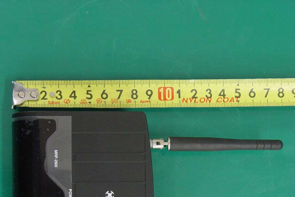
Click to zoom
Application Details
- Equipment Class
- CYY - Communications Receiver used w/Pt 15 Transmitter
- Date of Grant
- Oct 30, 2007
- Application Purpose
- Original Equipment
- Date of Application
- Oct 28, 2007
- Equipment Note
- RF RECEIVER
- Frequency Range
- 433.92000000 - 433.92000000
- Company
- Ohsung Electronics Co., Ltd.
- Country
- South Korea
Documents & Files
Document Text
Text extracted from the exhibit documents filed with the FCC. Open a document above to read the original.
Users Manual
EUT Type: RF Receiver FCC ID.: OZ5URCMRF260I Test Report No.: GETEC-E3-07-075 FCC Part 15 Subpart B APPENDIX I : USER’S MANUAL MRF-260i Installation Manual Optimizing Narrow Band Reception with Complete Control Remotes MRF-260i Installation Manual ©2007 Universal Remote Control, Inc. The information in this manual is copyright protected. No part of this man- ual may be copied or reproduced in any form without prior written consent from Universal Remote Control, Inc. UNIVERSAL REMOTE CONTROL, INC. SHALL NOT BE LIABLE FOR OPER- ATIONAL, TECHNICAL OR EDITORIAL ERRORS/OMISSIONS MADE IN THIS MANUAL. The Home Theater installation on the cover was designed and installed by Stone-Glidden of King of Prussia and Doylestown, PA. The information in this manual may be subject to change without prior notice. Complete Control is a registered trademark of Universal Remote Control, Inc. All other brand or product names are trademarks or registered trademarks of their respective companies or organizations. 500 Mamaroneck Avenue, Harrison, NY 10528 Phone: (914) 835-4484 Fax: (914) 835-4532 TABLEO F CONTENTS Introduction1 Features and Benefits2 Parts Guide2 Installation3 Testing5 Front Blaster Overload6 Disabling the Front Blaster - Step by Step via PC 6 Controlling Four Identical Components/Zones 7 Identical Components/Zones - Step by Step via PC 7 Programming For Multiple Equipment Locations 10 USA Limited Warranty Statement11 Frequently Asked Questions12 Specifications12 Page 1 MRF-260i B ASESTATION Introduction The MRF-260i base station is an “addressable” base station. RF Addressing gives you the ability to control as many as 60 identical components throughout a house. To enable better range and reliabili- ty the MRF-260i is equipped with the Narrow Band RF reception (like the MRF-350i), so is only compatible with other Narrow Band remotes. 1. MX/TX remote controls send radio waves in every direction, so your client enjoys “No More Pointing” operation! NOTE:The MRF-260i is ONLY compatible with Narrow Band remotes: the current versions of the MX-3000i, MX-900i remote controls. The MRF- 260i is compatible with all MX-900is and MX-3000is. You can identify the build date of a remote control by looking at the serial number. The first 6 digits indicate the build date. If the serial number appears as 122905 014054, the first 6 digits indicate that the remote was built on December 29, 2005. 2. The MRF-260i’s integrated Narrow Band RF receiver receives com- mands from any Narrow Band remote control. 3. The MRF-260i’s built-in Front Blaster sends commands to compo- nents in the same cabinet space as the MRF-260i. 4. Self-adhesive “Flashers” affix to the front panels of your client’s compo- nents (over the built-in IR sensor). The Flashers relay commands to components out of sight of the MRF- 260i’s Front Blaster. The flashers plug in to the MRF-260i’s rear flasher line outputs via their 10 foot cables. Uniquely, the MRF-260i can also con- nect to rear panel IR Inputs via its two adjustable Outputs. Page 2 MRF-260i BASESTATION Features and Benefits Interference Rejection and Extended Range via Narrow Band The MRF-260i receives RF (radio frequency) signals via its integrated RF receiver and antenna. The MRF-260i displays RF interference via a bright red Status LED, which flickers when interference is present if the ID is set to 0. Simply relocate the MRF-260i should interference occur. Two Fixed IR Outputs The MRF-260i is equipped with two fixed IR line outputs with standard 3.5 jacks for standard IR emitter/flashers. Two Variable IR Outputs Match Rear Panel IR Inputs The MRF-260i is equipped with two adjustable IR line outputs. Each output can be individually matched to rear panel IR inputs on any component that is designed to be operated by a standard IR repeater. The outputs utilize a 3.5mm jack and are compatible with standard IR emitter/flashers as well. Up To Fifteen Equipment Locations With Identical Components Each MX/TX remote is “addressable.” They can be programmed to specifically control components in a particular room by installing an MRF-260i base station at each location . In operation it’s simple: when you select a device located in the Den, the MX/TX remote only sends commands to the Den. When you select a device located in the Family Room, the MX/TX remote only sends commands to it. ASingle MRF-260i Can Control an Array of Identical Components or Identical Zones of a Multi Zone Preamp/Matrix Switcher Each MRF-260i has four “addressable” IR Line Outputs. For example, you can control up to four identical TV’s with one MRF-260i or route volume commands for a specific zone to a particular zone IR input on a multi-zone preamp. If you have more than four identical compo- nents or zones, up to 15 additional MRF-260is can be installed to con- trol them (thus allowing up to 60 identical components or zones in one house). Parts Guide The MRF-260i RF Base Station includes: 1 - MRF-260i Base Station 1 - Mounting Plate for wall mounting the MRF-260i 4 - Screws for wall mounting 1 - 9V-300mA Power Supply 4 - Visible Flashers with 10 foot plug in cables. 4 - Extra self adhesive pads for Emitters 12 - Labels for IR Line Outputs 1 - Screwdriver for Variable Outputs Page 3 Installation 1. Unplug the MRF-260i. Test all IR commands and macros line of sight. 2. Power on all AV components including the TV. Turn on all of the lights and lower all dimmers to 50%. Power on anything that may create RF Interference (particularly devices with high speed microprocessors or hard drives). 3. Check that the address wheel on the rear of the MRF-260i is set to ID#0 (the interference “sniffing” position). 4. Connect the MRF-260i to its DC wall adapter and plug the wall adapter into a live AC outlet. Place the MRF-260i in a location at least 3 feet away from satellite receivers, cable boxes, HDTV tuners, DVRs, PCs or any other device with a high speed micro- processor (these generate broad band Radio Frequency Interference -RFI). O…
Text truncated - open the document above for the full version.
Attestation Statements
EUT Type: RF Receiver FCC ID.: OZ5URCMRF260I Test Report No.: GETEC-E3-07-075 FCC Part 15 Subpart B APPENDIX A : ATTESTATION STATEMENT April 01, 2007 Federal Communications Commission Authorization and Evaluation Division Equipment Authorization Branch 7435 Oakland Mills Road Columbia, MD 21046 U.S.A To whom it may concern: We, the undersigned, hereby authorize GUMI College EMC Center to act on our behalf in all matters relating to applications for equipment authorization, including the signing of all documents relation to these matters. Any and all acts carried out by GUMI College EMC Center on our behalf shall have the same effect as acts of our own. We also hereby certify that no party to the application is subject of a denial of benefits, including FCC benefits, pursuant 5301 of the Anti-Drug Abuse Act of 1988, 21 U.S.C. 853(a). Sincerely, Kwang-jae Ok, Manager OHSUNG Electronics Co., Ltd.
Block Diagram
EUT Type: RF Receiver FCC ID.: OZ5URCMRF260I Test Report No.: GETEC-E3-07-075 FCC Part 15 Subpart B APPENDIX D : BLOCK DIAGRAM Port I/O and Interrupt Control SAM87RI CPU 15-Kbyte ROM 256-Byte Register File Port 0(INTR) Port 2 P0.0 Carrier Generator (Counter A) Main OSC (4MHz) 8-bit Timer/ Counter 8-bit BasicTimer 16-bit Timer/ Counter Port 1 Internal Bus LVD TEST X in X out P0.0-P0.7/INT0-INT4 P2.0/TOPWM P2.1/REM P2.2 IR OUT - 내장 IR OUT - 1IR OUT - 2IR OUT - 3IR OUT - 4 P1.0 P1.1 P1.3 P1.2 P1.4 RF Receiver AUTOMATIC GAIN CONTROL 3.3V REG DIVIDE BY 64 PHASE DETECTO R VCO LOOP FILTER CRYSTAL DRIVER POWER DOWN RSSI 0 º 90 º LNA +1 +2 Q I ∑ +- -+ +- DATA SLICER IMAGE REJECTION DATA FILTER R DF2 100㏀ R DF1 100㏀ 3 2,7 4 15 6 8 9 11 12 16 1 28 27 25 20 23 19 26 21 22 17 18 2414 13 5,10
Cover Letter(s)
OHSUNG ELECTRONICS CO., LTD #181 Gongdan-Dong, Gumi-Si,Gyeongsangbuk-Do, Korea Tel: +82-54-468-7282, Fax: +82-54-461-8368 TIMCO ENGINEERING INC. 849 NW State Road 45 Newberry, Florida 32669 Subject: Confidentiality Request regarding application for certification FCC ID: OZ5URCMRF260I Dear TEI; Pursuant to Sections 0.457 and 0.459 of the Commission’s Rules, we hereby request confidential treatment of information accompanying this application as outlined below: z SCHEMETIC DIAGRAM(S) : URCMRF260I_SchDia.pdf z OPERATIONAL DESCRIPTION : URCMRF260I_OpeDes.pdf The above materials contain trade secrets and proprietary information not customarily released to the public. The public disclosure of these materials may be harmful to the applicant and provide unjustified benefits to its competitors. The applicant understands that pursuant to Section 0.457 of the Rules, disclosure of this application and all accompanying documentation will not be made before the date of the Grant for this application. Sincerely, --------------------------------------------- Kwang-Jae Ok, Q.C Manager OHSUNG ELECTRONICS CO.,LTD
External Photos
EUT Type: RF Receiver FCC ID.: OZ5URCMRF260I Test Report No.: GETEC-E3-07-075 FCC Part 15 Subpart B APPENDIX G : EXTERNAL PHOTOGRAPHS EUT Type: RF Receiver FCC ID.: OZ5URCMRF260I Test Report No.: GETEC-E3-07-075 FCC Part 15 Subpart B EUT Type: RF Receiver FCC ID.: OZ5URCMRF260I Test Report No.: GETEC-E3-07-075 FCC Part 15 Subpart B EUT Type: RF Receiver FCC ID.: OZ5URCMRF260I Test Report No.: GETEC-E3-07-075 FCC Part 15 Subpart B EUT Type: RF Receiver FCC ID.: OZ5URCMRF260I Test Report No.: GETEC-E3-07-075 FCC Part 15 Subpart B
ID Label/Location Info
EUT Type: RF Receiver FCC ID.: OZ5URCMRF260I Test Report No.: GETEC-E3-07-075 FCC Part 15 Subpart B APPENDIX C : ID SAMPLE LABEL & LOCATION EUT Type: RF Receiver FCC ID.: OZ5URCMRF260I Test Report No.: GETEC-E3-07-075 FCC Part 15 Subpart B LABELLING REQUIREMENTS The label shown shall be permanently affixed at a conspicuous location on the device and be readily visible to the user at the time of purchase. ID Label ID Label Location of EUT ID Label
Internal Photos
EUT Type: RF Receiver FCC ID.: OZ5URCMRF260I Test Report No.: GETEC-E3-07-075 FCC Part 15 Subpart B APPENDIX H : INTERNAL PHOTOGRAPHS EUT Type: RF Receiver FCC ID.: OZ5URCMRF260I Test Report No.: GETEC-E3-07-075 FCC Part 15 Subpart B EUT Type: RF Receiver FCC ID.: OZ5URCMRF260I Test Report No.: GETEC-E3-07-075 FCC Part 15 Subpart B EUT Type: RF Receiver FCC ID.: OZ5URCMRF260I Test Report No.: GETEC-E3-07-075 FCC Part 15 Subpart B EUT Type: RF Receiver FCC ID.: OZ5URCMRF260I Test Report No.: GETEC-E3-07-075 FCC Part 15 Subpart B EUT Type: RF Receiver FCC ID.: OZ5URCMRF260I Test Report No.: GETEC-E3-07-075 FCC Part 15 Subpart B EUT Type: RF Receiver FCC ID.: OZ5URCMRF260I Test Report No.: GETEC-E3-07-075 FCC Part 15 Subpart B EUT Type: RF Receiver FCC ID.: OZ5URCMRF260I Test Report No.: GETEC-E3-07-075 FCC Part 15 Subpart B
Test Report
EUT Type: RF Receiver FCC ID.: OZ5URCMRF260I Test Report No.: GETEC-E3-07-075 FCC Part 15 Subpart B APPENDIX B : TEST PLOTS EUT Type: RF Receiver FCC ID.: OZ5URCMRF260I Test Report No.: GETEC-E3-07-075 FCC Part 15 Subpart B RF Receiving mode 0 5 10 15 20 25 30 35 40 45 50 55 60 65 70 75 80 150k 300 400 500 800 1M2M3M 4M 5M 6 8 10M20M30M Level in dB 킮 Frequency in Hz EN 55022_class B_QP EN 55022_class B_AV < Hot line > 0 5 10 15 20 25 30 35 40 45 50 55 60 65 70 75 80 150k 300 400 500 800 1M2M3M4M 5M 6 8 10M20M30M Level in dB 킮 Frequency in Hz EN 55022_class B_QP EN 55022_class B_AV < Neutral line >
Test Report
EUT Type: RF Receiver FCC ID.: OZ5URCMRF260I Page 2 of 21 Test Report No.: GETEC-E3-07-075 FCC Part 15 Subpart B CONTENTS 1. GENERAL INFORMATION ......................................................................................................................................4 2. INTRODUCTION ........................................................................................................................................................5 3. PRODUCT INFORMATION ......................................................................................................................................6 3.1 DESCRIPTION OF EUT..............................................................................................................................................6 3.2 SUPPORT EQUIPMENT / CABLES USED.....................................................................................................................7 3.3 MODIFICATION ITEM(S)...........................................................................................................................................7 4. DESCRIPTION OF TESTS.........................................................................................................................................8 4.1 TEST CONDITION......................................................................................................................................................8 4.2 CONDUCTED EMISSION............................................................................................................................................9 4.3 RADIATED EMISSION..............................................................................................................................................10 5. CONDUCTED EMISSION........................................................................................................................................ 11 5.1 OPERATING ENVIRONMENT................................................................................................................................... 11 5.2 TEST SET-UP............................................................................................................................................................ 11 5.3 MEASUREMENT UNCERTAINTY.............................................................................................................................. 11 5.4 LIMIT......................................................................................................................................................................12 5.5 TEST EQUIPMENT USED..........................................................................................................................................12 5.6 TEST DATA FOR POWER LINE CONDUCTED EMISSION............................................................................................13 6. RADIATED EMISSION ............................................................................................................................................14 6.1 OPERATING ENVIRONMENT...................................................................................................................................14 6.2 TEST SET-UP............................................................................................................................................................14 6.3 MEASUREMENT UNCERTAINTY..............................................................................................................................14 6.4 LIMIT......................................................................................................................................................................15 6.5 TEST EQUIPMENT USED..........................................................................................................................................15 6.6 RADIATED EMISSION TEST DATA............................................................................................................................16 7. ANTENNA POWER CONDUCTION ......................................................................................................................18 7.1 OPERATING ENVIRONMENT...................................................................................................................................18 7.2 TEST SET-UP............................................................................................................................................................18 7.3 TEST EQUIPMENT USED..........................................................................................................................................18 7.4 TEST DATA FOR ANTENNA POWER CONDUCTION...................................................................................................18 8. SAMPLE CALCULATIONS.....................................................................................................................................20 8.1 EXAMPLE 1 :...........................................................................................................................................................20 8.2 EXAMPLE 2 :...........................................................................................................................................................20 9. RECOMMENDATION & CONCLUSION..............................................................................................................21 APPENDIX A – ATTESTATION STATEMENT APPENDIX B – TEST PLOTS APPENDIX C – FCC ID LABEL & LOCATION APPENDIX D – BLOCK DIAGRAM(S) APPENDIX E – SCHEMATIC DIAGRAM(S) EUT Type: RF Receiver FCC ID.: OZ5URCMRF260I Page 3 of 21 Test Report No.: GETEC-E3-07-075 FCC Part 15 Subpart B APPENDIX F – TEST SET UP PHOTOS APPENDIX G – EXTERNAL PHOTOGRAPHS APPENDIX H – INTERNAL PHOTOGRAPHS APPENDIX I – USER’S MANUAL APPENDIX J – OPERATIONAL DESCRIPTION EUT Type: RF Receiver FCC ID.: OZ5URCMRF260I Page 4 of 21 Test Report No.: GETE…
Text truncated - open the document above for the full version.
Test Setup Photos
EUT Type: RF Receiver FCC ID.: OZ5URCMRF260I Test Report No.: GETEC-E3-07-075 FCC Part 15 Subpart B APPENDIX F : TEST SET UP PHOTOGRAPHS EUT Type: RF Receiver FCC ID.: OZ5URCMRF260I Test Report No.: GETEC-E3-07-075 FCC Part 15 Subpart B The Conducted Test Picture and Radiated Test Picture show the worst-case configuration and cable placement. Conducted Test Picture (Front) Conducted Test Picture (Rear) EUT Type: RF Receiver FCC ID.: OZ5URCMRF260I Test Report No.: GETEC-E3-07-075 FCC Part 15 Subpart B Radiated Test Picture (Front) Radiated Test Picture (Rear)
Contact Information
Applicant
Hak-Ki Kim(General Manager)
Test Firm
GUMI UNIVERSITY EMC CENTERTea-Sig Park
Technical Specifications
| # | Rule Parts | Frequency Range | Power Output |
|---|---|---|---|
| 1 | 15B | 433.92 MHz - 433.92 MHz | - |
Other Applications from Ohsung Electronics Co., Ltd.
OZ5PSRMT
Jan 13, 2026RF4CE RCU
Equipment Class
DTS - Digital Transmission SystemOZ5G32
Dec 29, 2025Remote Controller
Equipment Class
DTS - Digital Transmission SystemOZ5PSEMR
Dec 19, 2025RF Module
Equipment Class
DTS - Digital Transmission SystemOZ5G22
Dec 16, 2025Remote Controller
Equipment Class
DTS - Digital Transmission SystemOZ5G12
Dec 16, 2025Remote Controller
Equipment Class
DTS - Digital Transmission System