OZ5URCMX5000IRF REMOTE CONTROLLER
Ohsung Electronics Co., Ltd.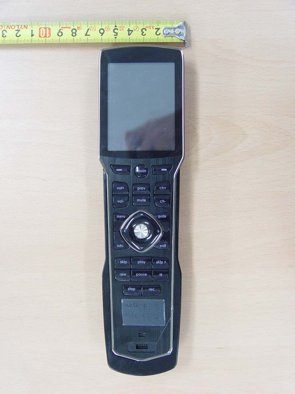
Click to zoom
Application Details
- Equipment Class
- DSC - Part 15 Security/Remote Control Transmitter
- Date of Grant
- Jun 07, 2010
- Application Purpose
- Original Equipment
- Date of Application
- Jun 06, 2010
- Equipment Note
- RF REMOTE CONTROLLER
- Frequency Range
- 433.92000000 - 433.92000000
- Company
- Ohsung Electronics Co., Ltd.
- Country
- South Korea
Documents & Files
Document Text
Text extracted from the exhibit documents filed with the FCC. Open a document above to read the original.
Users Manual
Order Number : GETEC-C1-10-122 FCC Certification Test Report Number : GETEC-E3-10-062 Page 1 / 1 EUT Type: RF remote controller FCC ID.: OZ5URCMX5000I APPENDIX H : USER’S MANUAL Operating Your System With The MX-5000i Two Way Touch Screen This remote control was Custom Programmed for you by: For questions about your Custom Programming call: Custom Programming of a complex home theater and/or a multi-room system is one of the most challenging tasks within an audio/video installation. It involves an intimate knowledge of how the components interact and exact details on the proper sequences of control. Only a Complete Control dealer has the requisite experience and training to quickly and effectively cus- tomize a remote control for true automated operation. Congratulations on your choice! MX-5000i Owners Manual © 2009 Universal Remote Control, Inc. The information in this manual is copyright protected. No part of this manual may be copied or reproduced in any form without prior written consent from Universal Remote Control, Inc. UNIVERSAL REMOTE CONTROL, INC. SHALL NOT BE LIABLE FOR OPERATIONAL, TECHNICAL OR EDITORIAL ERRORS/OMISSIONS MADE IN THIS MANUAL. The information in this manual may be subject to change without prior notice. Complete Control is a registered trademark of Universal Remote Control, Inc. Entertainment Made Simple is a trademark of Universal Remote Control, Inc. All other brand or product names are trademarks or registered trademarks of their respective companies or organizations. 500 Mamaroneck Avenue, Harrison, NY 10528 Phone: (914) 835-4484 Fax: (914) 835-4532 MX-5000i TWOWAYTOUCHSCREEN Table of Contents Introduction1 Connecting the Battery Pack2 Using the Charging Base2 Two Way via Wi-Fi2 Optional RF “No Rules” Operation3 Operating Your System4 Using Two Way Personal Server Features5 Revolutionary New iPod Controls 6 Displaying the Settings Screen9 Sleep Settings9 Network9 Brightness10 System10 Button Light10 Power Settings10 Calibration11 Date and Time11 Sound11 Pickup Settings11 Factory Default11 Exit11 Maintaining Your MX-5000i12 USA Limited Warranty Statement12 Specifications14 Federal Communication Commission Interference Statement15 Regulatory Information to the user16 Declaration of Conformity17 Precautions and Information Concerning Rechargeable Lithium-lon Batteries18 Page 1 MX-5000i TWOWAYTOUCHSCREEN Congratulations You’ve purchased a unique synthesis of hardware and software engineer- ing, the Complete Control MX-5000i. The twin goals of the design team were to improve the elegance and usability of touch screens through the physical design while providing a new standard in brightness, clarity and animation for the touch screen itself. Easy Operation By assigning the important home theater operational buttons to the natural resting place of the end users thumbs, the MX-5000i achieves a new standard in use and comfort. Automatic Backlighting The integral motion sensor detects any movement of the touch screen and automatically backlights the screen. You do not have to press any button to display the screen. Any movement of the MX-5000i renews the backlighting. To adjust the backlighting, see page 9. Programming the MX-5000i To fully automate an audio/video system and integrate two way automation of servers etc. the programmer must have a detailed knowledge of each component, LAN configuration, Wi-Fi optimiza- tion and how the system is connected and operated. Only a trained and certified professional audio/video installer can install an MX- 5000i automation system in a timely and efficient manner. How do I reset the MX-5000i Normally, resetting the MX-5000i is not necessary. However, if the MX-5000i's touch screen freezes or if you notice unusual behavior, you should press the MAIN and EXIT buttons simultaneously for 3 seconds. It will restart the MX-5000i. Page 2 MX-5000i TWOWAYTOUCHSCREEN Connecting the Battery Pack Unlock the rear cover by pressing down on the spring lock at the top of the cover. Remove the cover. For shipment from the factory, the battery is left out of the MX-5000i. Place the battery into the battery compart- ment, making sure you align the contacts on the battery to the con- tacts on the MX-5000i. The battery will snap into place when aligned properly. Replace the cover and snap it into place. Using the Charging Base Plug the 6V DC adapter into a power outlet and into the back of the charging base. Gently place the MX-5000i into the cradle of the charging base. It automatically aligns itself to the contacts on the charging base. The status indicator should immediately light. Red indicates that it is charging. Blue shows that it is fully charged. There is no harm in leaving the MX-5000i on its charging base whenever it is not in use. Two Way via Wi-Fi To use the MX-5000i with any two way companion product, the MX-5000i must be configured by your installer to be part of a LAN (local area network) via a Wi-Fi b/g access point or router. This is not user configurable. If you have any questions, consult with your custom installer. Red indicates charging, Blue that the remote is fully charged. Page 3 MX-5000i TWOWAYTOUCHSCREEN 4. Self-adhesive “Flashers” affix to the Infrared sensors on the front panels of your components. Uniquely, all Complete Control base stations can also connect to components with rear panel IR Inputs via adjustable IR Line Outputs. The MSC-400 offers RS-232 control via rear panel connections as well. 3. The MSC-400 can control IR, RS232 and Relay con- trolled devices. 1. The MX-5000i sends radio waves in every direc- tion, so you don’t have to point the remote anymore! 2. The RFX-250i RF Sensor can be freely positioned for optimal recep- tion. Optional RF “No Rules” Operation In combination with an MSC-400 Master System Controller, or an RF Base Station, the MX-5000i can control your system without being in line-of-sight of the equipment. The MSC-400 enhances the capabilities of the MX-5000i by storing and issuing Smart…
Text truncated - open the document above for the full version.
Attestation Statements
Order Number : GETEC-C1-10-122 FCC Certification Test Report Number : GETEC-E3-10-062 Page 1 / 1 EUT Type: RF remote controller FCC ID.: OZ5URCMX5000I APPENDIX A : ATTESTATION STATEMENT Authorization DoC for computer peripheral portion OHSUNG ELECTRONICS CO., LTD #181 Gongdan-Dong, Gumi-Si,Gyeongsangbuk-Do, Korea Tel: +82-54-468-7282, Fax: +82-54-461-8368 Federal Communications Commission Authorization and Evaluation Division Equipment Authorization Branch 1435 Oakland Mills Road Columbia, MD 21046 U.S.A April 22, 2009 To whom it may concern: We, the undersigned, hereby authorize GUMI College EMC Center to act on our behalf in all matters relating to applications for equipment authorization, including the signing of all documents relation to these matters. Any and all acts carried out by GUMI College EMC Center on our behalf shall have the same effect as acts of our own. We also hereby certify that no party to the application is subject of a denial of benefits, including FCC benefits, pursuant 5301 of the Anti-Drug Abuse Act of 1988, 21 U.S.C. 853(a). Sincerely, --------------------------------------------- Kwang-Jae Ok, Q.C Manager OHSUNG ELECTRONICS CO.,LTD OHSUNG ELECTRONICS CO., LTD #181 Gongdan-Dong, Gumi-Si,Gyeongsangbuk-Do, Korea Tel: +82-54-468-7282, Fax: +82-54-461-8368 Federal Communications Commission Authorization and Evaluation Division Equipment Authorization Branch 1435 Oakland Mills Road Columbia, MD 21046 U.S.A May 31, 2010 Subject: FCC Application for OZ5URCMX5000I We, the undersigned, hereby attest to the fact that we will apply the Declaration of Conformity procedure to the class B computer peripheral portion of this composite filing. Sincerely, --------------------------------------------- Kwang-Jae Ok, Q.C Manager OHSUNG ELECTRONICS CO.,LTD
External Photos
Order Number : GETEC-C1-10-122 FCC Certification Test Report Number : GETEC-E3-10-062 Page 1 / 10 EUT Type: RF remote controller FCC ID.: OZ5URCMX5000I APPENDIX F : EXTERNAL PHOTOGRAPHS Order Number : GETEC-C1-10-122 FCC Certification Test Report Number : GETEC-E3-10-062 Page 2 / 10 EUT Type: RF remote controller FCC ID.: OZ5URCMX5000I <RF remote controller> Order Number : GETEC-C1-10-122 FCC Certification Test Report Number : GETEC-E3-10-062 Page 3 / 10 EUT Type: RF remote controller FCC ID.: OZ5URCMX5000I Order Number : GETEC-C1-10-122 FCC Certification Test Report Number : GETEC-E3-10-062 Page 4 / 10 EUT Type: RF remote controller FCC ID.: OZ5URCMX5000I Order Number : GETEC-C1-10-122 FCC Certification Test Report Number : GETEC-E3-10-062 Page 5 / 10 EUT Type: RF remote controller FCC ID.: OZ5URCMX5000I Order Number : GETEC-C1-10-122 FCC Certification Test Report Number : GETEC-E3-10-062 Page 6 / 10 EUT Type: RF remote controller FCC ID.: OZ5URCMX5000I <Charging cradle> Order Number : GETEC-C1-10-122 FCC Certification Test Report Number : GETEC-E3-10-062 Page 7 / 10 EUT Type: RF remote controller FCC ID.: OZ5URCMX5000I Order Number : GETEC-C1-10-122 FCC Certification Test Report Number : GETEC-E3-10-062 Page 8 / 10 EUT Type: RF remote controller FCC ID.: OZ5URCMX5000I <Adapter> Order Number : GETEC-C1-10-122 FCC Certification Test Report Number : GETEC-E3-10-062 Page 9 / 10 EUT Type: RF remote controller FCC ID.: OZ5URCMX5000I <Battery> Order Number : GETEC-C1-10-122 FCC Certification Test Report Number : GETEC-E3-10-062 Page 10 / 10 EUT Type: RF remote controller FCC ID.: OZ5URCMX5000I
ID Label/Location Info
Order Number : GETEC-C1-10-122 FCC Certification Test Report Number : GETEC-E3-10-062 Page 1 / 2 EUT Type: RF remote controller FCC ID.: OZ5URCMX5000I APPENDIX B : ID SAMPLE LABEL & LOCATION Order Number : GETEC-C1-10-122 FCC Certification Test Report Number : GETEC-E3-10-062 Page 2 / 2 EUT Type: RF remote controller FCC ID.: OZ5URCMX5000I LABELLING REQUIREMENTS ID Label ID Label Location of EUT The label shown shall be permanently affixed at a conspicuous location on the device and be readily visible to the user at the time of purchase. (Labeling requirement by 2.925(d)) a) The label area on the device is limited because the EUT is relatively small. Therefore, The label is placed inside the battery compartment b) The battery is designed for easy removal and the label will be visible whenever the battery is removed. c) The device will be marketed without the battery installed and the label will be readily visible at the time of purchase. ID Label
Internal Photos
Order Number : GETEC-C1-10-122 FCC Certification Test Report Number : GETEC-E3-10-063 Page 1 / 8 EUT Type: RF remote controller FCC ID.: OZ5URCMX5000I APPENDIX G : INTERNAL PHOTOGRAPHS Order Number : GETEC-C1-10-122 FCC Certification Test Report Number : GETEC-E3-10-063 Page 2 / 8 EUT Type: RF remote controller FCC ID.: OZ5URCMX5000I <RF remote controller> Antenna (433.92 MHz) Antenna (Wi-Fi) Order Number : GETEC-C1-10-122 FCC Certification Test Report Number : GETEC-E3-10-063 Page 3 / 8 EUT Type: RF remote controller FCC ID.: OZ5URCMX5000I Order Number : GETEC-C1-10-122 FCC Certification Test Report Number : GETEC-E3-10-063 Page 4 / 8 EUT Type: RF remote controller FCC ID.: OZ5URCMX5000I Order Number : GETEC-C1-10-122 FCC Certification Test Report Number : GETEC-E3-10-063 Page 5 / 8 EUT Type: RF remote controller FCC ID.: OZ5URCMX5000I Order Number : GETEC-C1-10-122 FCC Certification Test Report Number : GETEC-E3-10-063 Page 6 / 8 EUT Type: RF remote controller FCC ID.: OZ5URCMX5000I Order Number : GETEC-C1-10-122 FCC Certification Test Report Number : GETEC-E3-10-063 Page 7 / 8 EUT Type: RF remote controller FCC ID.: OZ5URCMX5000I <Charging cradle> Order Number : GETEC-C1-10-122 FCC Certification Test Report Number : GETEC-E3-10-063 Page 8 / 8 EUT Type: RF remote controller FCC ID.: OZ5URCMX5000I
Test Report
Order Number : GETEC-C1-10-122 FCC Certification Test Report Number : GETEC-E3-10-062 Page 1 / 1 EUT Type: RF remote controller FCC ID.: OZ5URCMX5000I APPENDIX K : ANTENNA SPECIFICATION
Test Report
Order Number : GETEC-C1-10-122 FCC Certification Test Report Number : GETEC-E3-10-062 Page 1 / 5 EUT Type: RF remote controller FCC ID.: OZ5URCMX5000I APPENDIX L : TEST PLOTS Order Number : GETEC-C1-10-122 FCC Certification Test Report Number : GETEC-E3-10-062 Page 2 / 5 EUT Type: RF remote controller FCC ID.: OZ5URCMX5000I Occupied bandwidth A TDS Att 40 dB * * * RBW 30 kHz VBW 100 kHz SWT 200 ms * Ref 99 dBμV/m Center 433.916 MHzSpan 2 MHz200 kHz/ 1 PK VIEW PRN 70 75 80 85 90 95 1 Marker 1 [T1 ] 76.09 dBμV/ m 433.464000000 MHz 2 Delta 2 [T1 ] -1.01 dB 936.000000000 kHz D1 94.56 dB* D2 74.56 dB* F1 F2 (433.92 MHz) Order Number : GETEC-C1-10-122 FCC Certification Test Report Number : GETEC-E3-10-062 Page 3 / 5 EUT Type: RF remote controller FCC ID.: OZ5URCMX5000I Complete Pulse Train/ On-time of the Head Order Number : GETEC-C1-10-122 FCC Certification Test Report Number : GETEC-E3-10-062 Page 4 / 5 EUT Type: RF remote controller FCC ID.: OZ5URCMX5000I Order Number : GETEC-C1-10-122 FCC Certification Test Report Number : GETEC-E3-10-062 Page 5 / 5 EUT Type: RF remote controller FCC ID.: OZ5URCMX5000I
Test Report
Order Number : GETEC-C1-10-122 FCC Certification Test Report Number : GETEC-E3-10-062 Page2 / 23 EUT Type: RF remote controller FCC ID.: OZ5URCMX5000I CONTENTS 1. GENERAL INFORMATION ...................................................................................................................................... 4 2. INTRODUCTION ........................................................................................................................................................ 5 3. PRODUCT INFORMATION ...................................................................................................................................... 6 3.1 DESCRIPTION OF EUT .............................................................................................................................................. 6 3.2 SUPPORT EQUIPMENT / CABLES USED ..................................................................................................................... 7 3.3 MODIFICATION ITEM(S) ........................................................................................................................................... 7 4. ANTENNA REQUIREMENT - §15.203 ..................................................................................................................... 7 4.1 DESCRIPTION OF ANTENNA ...................................................................................................................................... 7 5. INTER MODULATION COMPLIANCE STATEMENT ......................................................................................... 8 6. DESCRIPTION OF TESTS ......................................................................................................................................... 8 6.1 TEST CONDITION ...................................................................................................................................................... 8 6.2 CONDUCTED EMISSION ............................................................................................................................................ 9 6.3 RADIATED EMISSION .............................................................................................................................................. 10 6.4 DUTY CYCLE CORRECTION ................................................................................................................................... 11 6.5 OCCUPIED BANDWIDTH ......................................................................................................................................... 11 7. CONDUCTED EMISSION ........................................................................................................................................ 12 7.1 OPERATING ENVIRONMENT ................................................................................................................................... 12 7.2 TEST SET-UP ............................................................................................................................................................ 12 7.3 MEASUREMENT UNCERTAINTY .............................................................................................................................. 12 7.4 LIMIT ...................................................................................................................................................................... 13 7.5 TEST EQUIPMENT USED .......................................................................................................................................... 13 7.6 TEST DATA FOR POWER LINE CONDUCTED EMISSION ............................................................................................ 13 8. DUTY CYCLE CORRECTION ................................................................................................................................ 16 8.1 OPERATING ENVIRONMENT ................................................................................................................................... 16 8.2 TEST SET-UP ........................................................................................................................................................... 16 8.3 TEST EQUIPMENT USED .......................................................................................................................................... 16 8.4 TEST RESULT OF DUTY CYCLE ............................................................................................................................... 16 9. RADIATED EMISSION ............................................................................................................................................ 17 9.1 OPERATING ENVIRONMENT ................................................................................................................................... 17 9.2 TEST SET-UP ............................................................................................................................................................ 17 9.3 MEASUREMENT UNCERTAINTY .............................................................................................................................. 17 9.4 LIMIT ...................................................................................................................................................................... 18 9.5 TEST EQUIPMENT USED .......................................................................................................................................... 18 9.6 RADIATED EMISSION TEST DATA ............................................................................................................................ 19 10. OCCUPIED BANDWIDTH MEASUREMENT .................................................................................................... 21 10.1 OPERATING ENVIRONMENT ..................................................................................................................…
Text truncated - open the document above for the full version.
Test Setup Photos
Order Number : GETEC-C1-10-122 FCC Certification Test Report Number : GETEC-E3-10-062 Page 1 / 4 EUT Type: RF remote controller FCC ID.: OZ5URCMX5000I APPENDIX E : TEST SET UP PHOTOGRAPHS Order Number : GETEC-C1-10-122 FCC Certification Test Report Number : GETEC-E3-10-062 Page 2 / 4 EUT Type: RF remote controller FCC ID.: OZ5URCMX5000I Conducted test picture (Front) Conducted test picture (Rear) Order Number : GETEC-C1-10-122 FCC Certification Test Report Number : GETEC-E3-10-062 Page 3 / 4 EUT Type: RF remote controller FCC ID.: OZ5URCMX5000I Radiated Test Picture (X axis) Radiated Test Picture (Y axis) Order Number : GETEC-C1-10-122 FCC Certification Test Report Number : GETEC-E3-10-062 Page 4 / 4 EUT Type: RF remote controller FCC ID.: OZ5URCMX5000I Radiated Test Picture (Z axis) Radiated Test Picture (with cradle)
Contact Information
Applicant
Hak-Ki Kim(General Manager)
Test Firm
Gumi University EMC CenterTae-Sig Park
Technical Specifications
| # | Rule Parts | Frequency Range | Power Output |
|---|---|---|---|
| 1 | 15.231 | 433.92 MHz - 433.92 MHz | - |
Other Applications from Ohsung Electronics Co., Ltd.
OZ5PSRMT
Jan 13, 2026RF4CE RCU
Equipment Class
DTS - Digital Transmission SystemOZ5G32
Dec 29, 2025Remote Controller
Equipment Class
DTS - Digital Transmission SystemOZ5PSEMR
Dec 19, 2025RF Module
Equipment Class
DTS - Digital Transmission SystemOZ5G22
Dec 16, 2025Remote Controller
Equipment Class
DTS - Digital Transmission SystemOZ5G12
Dec 16, 2025Remote Controller
Equipment Class
DTS - Digital Transmission System