OZ5URCMX900IRF REMOTE CONTROLLER
Ohsung Electronics Co., Ltd.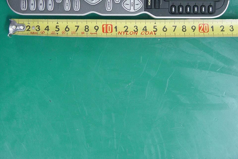
Click to zoom
Application Details
- Equipment Class
- DSC - Part 15 Security/Remote Control Transmitter
- Date of Grant
- May 22, 2007
- Application Purpose
- Original Equipment
- Date of Application
- May 20, 2007
- Equipment Note
- RF REMOTE CONTROLLER
- Frequency Range
- 433.92000000 - 433.92000000
- Company
- Ohsung Electronics Co., Ltd.
- Country
- South Korea
Documents & Files
Document Text
Text extracted from the exhibit documents filed with the FCC. Open a document above to read the original.
Users Manual
EUT Type: Remote Controller FCC ID.: OZ5URCMX900I Test Report No.: GETEC-E3-07-041 FCC Part 15 Subpart B,C APPENDIX I : USER’S MANUAL Operating Your System With The MX-900i TABLEO FCONTENTS This remote control was Custom Programmed for you by: For questions about your Custom Programming call: Custom Programming of a complex home theater and/or a multi-room system is one of the most challenging tasks within an audio/video instal- lation. It involves an intimate knowledge of how the components interact and exact details on the proper sequences of control. Only a Complete Control dealer has the requisite experience and training to quickly and effectively customize a remote control for true automated operation. Congratulations on your choice! MX-900i Owners Manual © 2006 Universal Remote Control, Inc. Front Cover Photo courtesy of Robert Ridenour of Connected Technologies, www .connected-technologies.com The information in this manual is copyright protected. No part of this manual may be copied or reproduced in any form without prior written consent from Universal Remote Control, Inc. UNIVERSAL REMOTE CONTROL, INC. SHALL NOT BE LIABLE FOR OPERATIONAL, TECHNICAL OR EDITORIAL ERRORS/OMISSIONS MADE IN THIS MANUAL. The information in this manual may be subject to change without prior notice. Complete Control is a registered trademark of Universal Remote Control, Inc. Entertainment Made Simple is a trademark of Universal Remote Control, Inc. All other brand or product names are trademarks or registered trademarks of their respective companies or organizations. Universal Remote Control, Inc. 500 Mamaroneck Avenue, Harrison, NY 10528 Phone: (914) 835-4484 Fax: (914) 835-4532 Introduction1 The LIGHT Button1 Optional RF “No Rules” Operation2 Installing Batteries3 Programming the MX-900i4 Selecting a New “Activity”5 Using the MX-900i to Control an “Activity”6 Displaying the Setup Screen7 Selecting from the Setup Screen7 Setting the LCD8 Sound Volume10 Light Settings10 System Settings11 Version Information Displays11 Warranty12 Specifications12 Information To The User 13 Warning 13 Universal Remote Control ® Page 2 MX-900i OWNERS MANUAL MX-900i OWNERS MANUAL Congratulations! You’ve purchased a unique synthesis of hardware and software engineering, the Complete Control MX-900i. The MX-900i achieves a magnificent combina- tion of power and flexibility, simplifying and automating operation of even the most complex system. One Touch Blue Backlighting Simply press the LIGHT button to backlight the screen. Integrated Sound Signaling The MX-900i incorporates a small speaker for beeps. Anytime you press a button, the MX-900i signals that it has understood your command with a beep sound. Custom Labeled Buttons The MX-900i is equipped with a bright easy to read LCD screen which labels the six buttons to the right of the screeen. These button labels change based on what you are watching or listening to. Thus, if you have selected Watching TV, you will see a list of buttons that are useful to that activity, while if you select DVD, the buttons will control the DVD. Optional RF “No Rules” Operation In combination with a Complete Control RF Base Station, the MX-900i can control your system without being in line-of-sight of the equipment. 3.The MRF-350i’s built-in Front Blaster sends commands to components in the same cabinet space as the MRF-350i. 4. Self-adhesive “Flashers”affix to the Infrared sensors on the front panels of your components.The Flashers relay commands to components out of sight of the MRF- 350i’s Front Blaster.The flashers plug in to the MRF-350i’s rear flasher line outputs via their 10 foot cables. Uniquely, the MRF-350i can also connect to rear panel IR Inputs via its adjustable IR Line Outputs. LIGHT Button Press the Light button on the side of the MX-900i to backlight the LCD display and all of the buttons. 2.The RFX-250i RF Sensor can be freely positioned for optimal reception. Either the MRF-350i or the RFX-250i RF base station is compatible with the MX-900i. Both incorporate RF addressing. RF Addressing gives you the ability to control equipment locations throughout your home, even if they are concealed in other rooms or are behind closed doors. 1.The MX-900i sends radio waves in every direction, so you don’t have to point the remote any- more! Page 1 Programming the MX-900i The MX-900i is programmed via a Windows PC equipped with a USB port (programming cable included), using our proprietary software, MX-900i Editor. You can download this software from our website: www .universalremote.com Basic setup takes only a few minutes with this software. However, to fully automate an audio/video system the user must have a detailed knowledge of each component, you the user (and your preferences) and how the system is connected and operated. We highly recommend that you use a professional audio/video installer to program your MX-900i so you will be able to enjoy all the benefits of the MX-900i as well as one touch operation via macros. Installing Batteries Open the battery cover by pressing the release and pulling back the cover on the back of the control. Remove the cover. Observe the + and - polarity indications inside the battery compartment. Place the four AAA batteries into their positions in the battery com- partment observing the + and - polarity indicators on the batteries. Now, replace the battery cover by inserting the hinged end in first, then snapping the cover back into place. Page 3 MX-900i OWNERS MANUAL Page 4 MX-900i OWNERS MANUAL + + - - Page 5 MX-900i OWNERS MANUAL Selecting a New “Activity” The MX-900i’s WATCH and LISTEN buttons display the activities you can control with your MX-900i. When you want to watch something else (a DVD movie, a videotape or an HDTV broadcast), simply press the WATCH button and select the new activity. When you want to listen to the radio or to a CD, touch the LISTEN button and select what you would like to listen to. Your installer will have programmed t…
Text truncated - open the document above for the full version.
Attestation Statements
EUT Type: Remote Controller FCC ID.: OZ5URCMX900I Test Report No.: GETEC-E3-07-041 FCC Part 15 Subpart B,C APPENDIX A : ATTESTATION STATEMENT April 01, 2007 Federal Communications Commission Authorization and Evaluation Division Equipment Authorization Branch 7435 Oakland Mills Road Columbia, MD 21046 U.S.A To whom it may concern: We, the undersigned, hereby authorize GUMI College EMC Center to act on our behalf in all matters relating to applications for equipment authorization, including the signing of all documents relation to these matters. Any and all acts carried out by GUMI College EMC Center on our behalf shall have the same effect as acts of our own. We also hereby certify that no party to the application is subject of a denial of benefits, including FCC benefits, pursuant 5301 of the Anti-Drug Abuse Act of 1988, 21 U.S.C. 853(a). Sincerely, Kwang-jae Ok, Manager OHSUNG Electronics Co., Ltd.
Block Diagram
EUT Type: Remote Controller FCC ID.: OZ5URCMX900I Test Report No.: GETEC-E3-07-041 FCC Part 15 Subpart B,C APPENDIX D : BLOCK DIAGRAM DATA ACTIVITY DETECTOR LOCK DETECT 32 × PLL CRYSTAL- OSCILLATOR DRIVER PA MAXIM MAX7044 SN74AC00PWR X-TAL2 /16 X-TAL2 PAOUT OSE_E VDD DATA VDD GND PAGND CLKOUT ANTENNA
Cover Letter(s)
OHSUNG ELECTRONICS CO., LTD #181 Gongdan-Dong, Gumi-Si, Gyeongsangbuk-Do, Korea Tel: +82-54-468-7282, Fax: +82-54-461-8368 Federal Communications Commission Authorization and Evaluation Division Confidentiality Request regarding application for certification of FCC ID: OZ5URCMX900I Pursuant to Sections 0.457 and 0.459 of the Commission’s Rules, we hereby request confidential treatment of information accompanying this application as outlined below: z Appendix E : Schematic Diagram z Appendix J : Operational Description The above materials contain trade secrets and proprietary information not customarily released to the public. The public disclosure of these materials may be harmful to the applicant and provide unjustified benefits to its competitors. The applicant understands that pursuant to Section 0.457 of the Rules, disclosure of this application and all accompanying documentation will not be made before the date of the Grant for this application. Sincerely, --------------------------------------------- Kwang-Jae Ok, Q.C Manager OHSUNG ELECTRONICS CO.,LTD Rev. 1/1/03
External Photos
EUT Type: Remote Controller FCC ID.: OZ5URCMX900I Test Report No.: GETEC-E3-07-041 FCC Part 15 Subpart B,C APPENDIX G : EXTERNAL PHOTOGRAPHS EUT Type: Remote Controller FCC ID.: OZ5URCMX900I Test Report No.: GETEC-E3-07-041 FCC Part 15 Subpart B,C EUT Type: Remote Controller FCC ID.: OZ5URCMX900I Test Report No.: GETEC-E3-07-041 FCC Part 15 Subpart B,C EUT Type: Remote Controller FCC ID.: OZ5URCMX900I Test Report No.: GETEC-E3-07-041 FCC Part 15 Subpart B,C
ID Label/Location Info
EUT Type: Remote Controller FCC ID.: OZ5URCMX900I Test Report No.: GETEC-E3-07-041 FCC Part 15 Subpart B,C APPENDIX C : ID SAMPLE LABEL & LOCATION EUT Type: Remote Controller FCC ID.: OZ5URCMX900I Test Report No.: GETEC-E3-07-041 FCC Part 15 Subpart B,C LABELLING REQUIREMENTS The label shown shall be permanently affixed at a conspicuous location on the device and be readily visible to the user at the time of purchase. ID Label ID Label Location of EUT ID Label
Internal Photos
EUT Type: Remote Controller FCC ID.: OZ5URCMX900I Test Report No.: GETEC-E3-07-041 FCC Part 15 Subpart B,C APPENDIX H : INTERNAL PHOTOGRAPHS EUT Type: Remote Controller FCC ID.: OZ5URCMX900I Test Report No.: GETEC-E3-07-041 FCC Part 15 Subpart B,C EUT Type: Remote Controller FCC ID.: OZ5URCMX900I Test Report No.: GETEC-E3-07-041 FCC Part 15 Subpart B,C EUT Type: Remote Controller FCC ID.: OZ5URCMX900I Test Report No.: GETEC-E3-07-041 FCC Part 15 Subpart B,C EUT Type: Remote Controller FCC ID.: OZ5URCMX900I Test Report No.: GETEC-E3-07-041 FCC Part 15 Subpart B,C EUT Type: Remote Controller FCC ID.: OZ5URCMX900I Test Report No.: GETEC-E3-07-041 FCC Part 15 Subpart B,C EUT Type: Remote Controller FCC ID.: OZ5URCMX900I Test Report No.: GETEC-E3-07-041 FCC Part 15 Subpart B,C EUT Type: Remote Controller FCC ID.: OZ5URCMX900I Test Report No.: GETEC-E3-07-041 FCC Part 15 Subpart B,C
Test Report
EUT Type: Remote Controller FCC ID.: OZ5URCMX900I Test Report No.: GETEC-E3-07-041 FCC Part 15 Subpart B,C APPENDIX B : TEST PLOTS EUT Type: Remote Controller FCC ID.: OZ5URCMX900I Test Report No.: GETEC-E3-07-041 FCC Part 15 Subpart B,C Occupied bandwidth EUT Type: Remote Controller FCC ID.: OZ5URCMX900I Test Report No.: GETEC-E3-07-041 FCC Part 15 Subpart B,C Complete Pulse Train/ On-time of the Head EUT Type: Remote Controller FCC ID.: OZ5URCMX900I Test Report No.: GETEC-E3-07-041 FCC Part 15 Subpart B,C EUT Type: Remote Controller FCC ID.: OZ5URCMX900I Test Report No.: GETEC-E3-07-041 FCC Part 15 Subpart B,C EUT Type: Remote Controller FCC ID.: OZ5URCMX900I Test Report No.: GETEC-E3-07-041 FCC Part 15 Subpart B,C Download mode < Hot line > < Neutral line >
Test Report
EUT Type: Remote Controller FCC ID.: OZ5URCMX900I Page 2 of 24 Test Report No.: GETEC-E3-07-041 FCC Part 15 Subpart B,C CONTENTS 1. GENERAL INFORMATION ......................................................................................................................................4 2. INTRODUCTION ........................................................................................................................................................5 3. PRODUCT INFORMATION ......................................................................................................................................6 3.1 DESCRIPTION OF EUT..............................................................................................................................................6 3.2 SUPPORT EQUIPMENT / CABLES USED.....................................................................................................................7 3.3 MODIFICATION ITEM(S)...........................................................................................................................................7 4. DESCRIPTION OF TESTS.........................................................................................................................................8 4.1 TEST CONDITION......................................................................................................................................................8 5. ANTENNA REQUIREMENT - §15.203 .....................................................................................................................8 5.1 DESCRIPTION OF ANTENNA......................................................................................................................................8 5.2 CONDUCTED EMISSION............................................................................................................................................9 5.3 RADIATED EMISSION..............................................................................................................................................10 5.4 DUTY CYCLE CORRECTION................................................................................................................................... 11 5.5 OCCUPIED BANDWIDTH......................................................................................................................................... 11 6. CONDUCTED EMISSION........................................................................................................................................12 6.1 OPERATING ENVIRONMENT...................................................................................................................................12 6.2 TEST SET-UP............................................................................................................................................................12 6.3 MEASUREMENT UNCERTAINTY..............................................................................................................................12 6.4 LIMIT......................................................................................................................................................................13 6.5 TEST EQUIPMENT USED..........................................................................................................................................13 6.6 TEST DATA FOR POWER LINE CONDUCTED EMISSION............................................................................................14 7. DUTY CYCLE CORRECTION................................................................................................................................15 7.1 OPERATING ENVIRONMENT...................................................................................................................................15 7.2 TEST SET-UP............................................................................................................................................................15 7.3 TEST EQUIPMENT USED..........................................................................................................................................15 7.4 TEST RESULT OF DUTY CYCLE...............................................................................................................................15 8. RADIATED EMISSION ............................................................................................................................................16 8.1 OPERATING ENVIRONMENT...................................................................................................................................16 8.2 TEST SET-UP............................................................................................................................................................16 8.3 MEASUREMENT UNCERTAINTY..............................................................................................................................16 8.4 LIMIT......................................................................................................................................................................17 8.5 TEST EQUIPMENT USED..........................................................................................................................................17 8.6 RADIATED EMISSION TEST DATA............................................................................................................................18 9. OCCUPIED BANDWIDTH MEASUREMENT......................................................................................................22 9.1 OPERATING ENVIRONMENT...................................................................................................................................22 9.2 TEST SET-UP............................................................................................................................................................22 9.3 LIMIT......................…
Text truncated - open the document above for the full version.
Test Setup Photos
EUT Type: Remote Controller FCC ID.: OZ5URCMX900I Test Report No.: GETEC-E3-07-041 FCC Part 15 Subpart B,C APPENDIX F : TEST SET UP PHOTOGRAPHS EUT Type: Remote Controller FCC ID.: OZ5URCMX900I Test Report No.: GETEC-E3-07-041 FCC Part 15 Subpart B,C The Conducted Test Picture and Radiated Test Picture show the worst-case configuration and cable placement. Conducted Test Picture (Front)_Download mode Conducted Test Picture (Rear) _ Download mode EUT Type: Remote Controller FCC ID.: OZ5URCMX900I Test Report No.: GETEC-E3-07-041 FCC Part 15 Subpart B,C Radiated Test Picture (Front) RF & IR mode Radiated Test Picture (Rear) RF & IR mode EUT Type: Remote Controller FCC ID.: OZ5URCMX900I Test Report No.: GETEC-E3-07-041 FCC Part 15 Subpart B,C Radiated Test Picture (Front) _Download mode Radiated Test Picture (Rear)_Download mode
Contact Information
Applicant
Hak-Ki Kim(General Manager)
Test Firm
GUMI UNIVERSITY EMC CENTERTea-Sig Park
Technical Specifications
| # | Rule Parts | Frequency Range | Power Output |
|---|---|---|---|
| 1 | 15.231 | 433.92 MHz - 433.92 MHz | - |
Other Applications from Ohsung Electronics Co., Ltd.
OZ5PSRMT
Jan 13, 2026RF4CE RCU
Equipment Class
DTS - Digital Transmission SystemOZ5G32
Dec 29, 2025Remote Controller
Equipment Class
DTS - Digital Transmission SystemOZ5PSEMR
Dec 19, 2025RF Module
Equipment Class
DTS - Digital Transmission SystemOZ5G22
Dec 16, 2025Remote Controller
Equipment Class
DTS - Digital Transmission SystemOZ5G12
Dec 16, 2025Remote Controller
Equipment Class
DTS - Digital Transmission System