OZ5URCMX980RF REMOTE CONTROLLER
Ohsung Electronics Co., Ltd.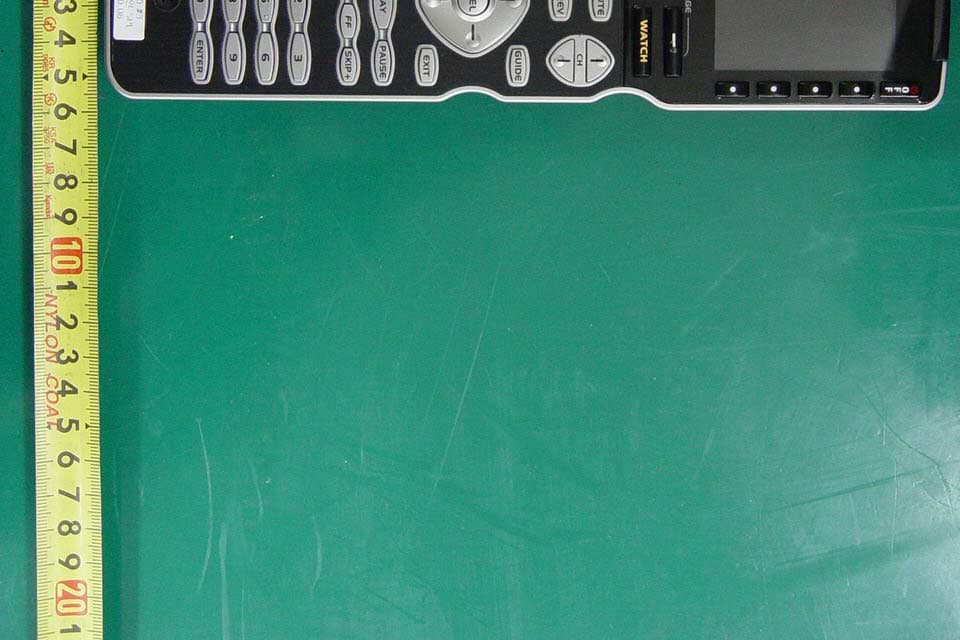
Click to zoom
Application Details
- Equipment Class
- DSC - Part 15 Security/Remote Control Transmitter
- Date of Grant
- Oct 24, 2007
- Application Purpose
- Original Equipment
- Date of Application
- Oct 22, 2007
- Equipment Note
- RF REMOTE CONTROLLER
- Frequency Range
- 418.00000000 - 418.00000000
- Company
- Ohsung Electronics Co., Ltd.
- Country
- South Korea
Documents & Files
Document Text
Text extracted from the exhibit documents filed with the FCC. Open a document above to read the original.
Users Manual
EUT Type: Remote Controller FCC ID.: OZ5URCMX980 Test Report No.: GETEC-E3-07-074 FCC Part 15 Subpart B,C APPENDIX I : USER’S MANUAL Operating Your System With the MX-980 This remote control was Custom Programmed for you by: For questions about your Custom Programming call: Custom Programming of a complex home theater and/or a multi- room system is one of the most challenging tasks within an audio/video installation. It involves an intimate knowledge of how the components interact and exact details on the proper sequences of control. Only a Complete Control dealer has the requisite experience and training to quickly and effectively customize a remote control for true automated operation. Congratulations on your choice! MX-980 Owners Manual © 2007 Universal Remote Control, Inc. Front Cover Photo courtesy of Stone Glidden, King of Prussia and Doylestown, PA www .stoneglidden.com The information in this manual is copyright protected. No part of this man- ual may be copied or reproduced in any form without prior written consent from Universal Remote Control, Inc. UNIVERSAL REMOTE CONTROL, INC. SHALL NOT BE LIABLE FOR OPERA- TIONAL, TECHNICAL OR EDITORIAL ERRORS/OMISSIONS MADE IN THIS MANUAL. The information in this manual may be subject to change without prior notice. Complete Control is a registered trademark of Universal Remote Control, Inc. Entertainment Made Simple is a trademark of Universal Remote Control, Inc. All other brand or product names are trademarks or registered trademarks of their respective companies or organizations. Universal Remote Control, Inc. 500 Mamaroneck Avenue, Harrison, NY 10528 Phone: (914) 835-4484 Fax: (914) 835-4532 MX-980 OWNERSMANUAL Table of Contents Introduction1 Using the Color LCD & the Screen Buttons1 Optional RF “No Rules” Operation2 Connecting the Battery Pack3 Using the Charging Base4 Programming the MX-9804 Selecting a New “Activity”5 Using the MX-980 to Control an “Activity”6 Displaying the Setup Screens7 Main Settings Menu8 Adjusting the Display8 Sound Volume9 System Settings Menu9 Information Menu10 Setting Time10 Specifications12 Information To The User13 Page 1 MX-980 OWNERSMANUAL Congratulations! You’ve purchased a unique synthesis of hardware and software engi- neering, the Complete Control MX-980. The MX-980 achieves a mag- nificent combination of power and flexibility, simplifying and automat- ing operation of even the most complex system. Automatic Backlighting The integral motion sensor detects any movement of the remote con- trol and automatically backlights the screen. You do not have to press any button to display the screen. Any movement of the MX- 980 renews the backlighting. Integrated Sound Signaling The MX-980 incorporates a small speaker for beeps. Anytime you press a button, the MX-980 signals that it has understood your com- mand with a beep sound. Using the Color LCD and the Screen Buttons The MX-980 is equipped with a bright easy to read LCD screen which your installer will customize for your system. The screen labels the eight hard buttons (easy to find by feel) positioned on either side of the screen. Normally, the screen is “split” so each button is allocated to a specific function (as shown on the right). This provides you with the ability to see and operate up to 8 functions on a single screen. However, your installer can com- bine two buttons to create a single row that can be accessed by either adjacent button. This simplifies operation for the entire family and enables convenient operation for both left and right-handed users for important functions you use fre- quently. Page 2 MX-980 OWNERSMANUAL Optional RF “No Rules” Operation In combination with an MSC-400 Master System Controller, or an RF Base Station, the MX-980 can control your system without being in line-of-sight of the equipment. The MSC-400 enhances the capabilities of the MX-980 by storing and issuing Smart Macros to your main system components. It is triggered by RF Smart Macro commands via RF (radio frequency). In addition, your MX-980 can control components in secondary rooms and systems via MRF-350 or MRF-260 RF base stations 3.The MSC-400 can control IR, RS232 and Relay controlled devices. 2.The RFX-250 RF Sensor can be freely positioned for optimal reception. 4. Self-adhesive “Flashers” affix to the Infrared sensors on the front panels of your components. Uniquely, all Complete Control base stations can also connect to components with rear panel IR Inputs via adjustable IR Line Outputs. The MSC-400 offers RS-232 control via rear panel con- nections as well. 1. The MX-980 sends radio waves in every direction, so you don’t have to point the remote anymore! Page 3 MX-980 OWNERSMANUAL Open the battery cover by depressing the release and pulling back the cover on the back of the control. Remove the cover. Observe the three contacts for the battery at the bottom left of the battery compartment. Observe the contacts on the battery First, angle the battery so that the contacts connect to the contacts inside the battery compartment. Then let the base of the battery down. Apply gentle pressure against the spring action of the con- tacts to fit the battery into place. Now, replace the battery cover. Connecting the Battery Pack Page 4 MX-980 OWNERSMANUAL Using the Charging Base Plug the 5V DC adapter into a power outlet and into the back of the charging base. Gently place the MX-980 into the cradle of the charging base. The Status light should immediately light. Red indicates that it is charging. Blue shows that it is fully charged. There is no harm in leaving the MX- 980 on its charging base whenever it is not in use. The Lithium Ion battery cannot be overcharged. Programming the MX-980 The MX-980 is programmed via a Windows PC equipped with a USB port (programming cable included), using our proprietary soft- ware, MX-980 Editor. You could download this software from our website: www .universalremote.com However, although some enthusiasts have learned to use …
Text truncated - open the document above for the full version.
Users Manual
Main Settings Menu Adjusting the Display Page 8 MX-980 O WNERSMANUAL DISPLAY- Press this setting button to adjust the screen and button backlight- ing. The longer your screen is lit, the more frequently you’ll need to charge the MX-980. SOUND - Adjust the volume of the sounds your MX-980 makes when you press buttons. SYSTEM - These settings are for service use. For diagnostic purposes, an installer can turn off the Pick Up sensor, display remaining battery charge and erase all programming permanently. Some of this menu may have been disabled by your installer as a safety measure. INFORMATION - Adjust the time, date or you can display the amount of mem- ory available and the version number of the firmware loaded into your MX-980. BACKLIGHT - Specify how long the MX-980 screen should stay lit after you press a button. You can select two dif- ferent time out settings. One for when it is hand held, another for when it is in the charging base. BRIGHT - Adjust the brightness of the screen. BUTTON LIGHT - Turn the backlighting for all buttons on or off. When on, all the buttons backlight so that you can read their labels in total darkness. System Settings Menu Page 9 MX-980 OWNERSMANUAL Sound Volume Press this button to raise the vol- ume. Press this button to cancel any changes you’ve made and return to the Main Setting menu. Press this button to lower the vol- ume. Press this button to save any changes you’ve made and return to the Main Setting menu. POWER- Displays the current power remaining and enables you to set the level that triggers a warning when you are using the MX-980. PICKUP - The MX-980 normally turns itself on when its angle is changed. This can be disabled for diagnostic purposes. FACTORY DEFAULT - WARNING! This setting is for service use. Your installer can erase all programming per- manently, before downloading your configuration back into the MX-980 via his/her PC. This button may have been disabled by your installer as a safety measure. Setting Time Information Menu Page 10 MX-980 OWNERSMANUAL Each time you press this button the hour will change. Each time you press this button the minute will change. Press this button to cancel any changes you’ve made and return to the Main Setting menu. Press this button to change from AM to PM. Press this button to save any changes you’ve made and return to the Main Setting menu. Press this button to turn daylight savings time on. Press this button to turn daylight savings time off. DATE- Press this button to set the date. TIME - Press this button to set the time. MEMORY - Press this button to display the amount of memory available. VERSION - Press this button to display the version of the MX-980 firmware. Page 11 MX-980 OWNERSMANUAL USA Limited Warranty Statement Your Universal Remote Control, when delivered to you in new condi- tion, is warranted against defects in materials or workmanship as fol- lows: UNIVERSAL REMOTE CONTROL, INC. warrants this product against defects in material or workmanship for a period of one (1) year and as set forth below. Universal Remote Control will, at its sole option, repair the product using new or comparable rebuilt parts, or exchange the product for a comparable new or rebuilt product. In the event of a defect, these are your exclusive remedies. This Limited Warranty covers only the hardware components packaged with the Product. It does not cover technical assistance for hardware or software usage and it does not cover any software products whether or not contained in the Product; any such software is provided "AS IS" unless expressly pro- vided for in any enclosed software Limited Warranty. To obtain warranty service, you must deliver the product, freight prepaid, in its original packaging or packaging affording adequate protection to Universal Remote Control at the address provided in the Owner's Manual. It is your responsibility to backup any macro programming, artwork, software or other materials that may have been programmed into your unit. It is likely that such data, software, or other materials will be lost during service and Universal Remote Control will not be responsible for any such damage or loss. A dated purchase receipt, Bill of Sale, Installation Contract or other veri- fiable Proof of Purchase is required. For product support and other impor- tant information visit Universal Remote Control's website: http://www .UniversalRemote.com Or call the Universal Remote Control Customer Service Center (914) 835-4484. This Limited Warranty only covers product issues caused by defects in mate- rial or workmanship during ordinary consumer use. It does not cover prod- uct issues caused by any other reason, including but not limited to product issues due to commercial use, acts of God, third-party installation, misuse, limitations of technology, or modification of or to any part of the Universal Remote Control product. This Limited Warranty does not cover Universal Remote Control products sold as USED, AS IS, REFURBISHED, so-called "B STOCK" or consumables (such as batteries). This Limited Warranty is invalid if the factory-applied serial number has been altered or removed from the product. This Limited Warranty is valid only in the United States of America. This Limited Warranty specifically excludes products sold by unauthorized resellers. Page 12 MX-980 OWNERSMANUAL Specifications Microprocessor: ARM9 32bit 202MHz LCD - 2.4” TFT (QVGA) 262,144 Colors Memory - 64 Megabytes of SDRAM & 32 Megabytes of Nand Flash Devices - Supports up to 255 Devices with text, less with heavy graphics usage Pages - Supports up to 255 Pages on each Device with text, less with heavy graphics usage Learning Capability - Standard frequencies (15kHz to 455kHz) Macro Capability - Up to 255 steps each, however nesting is allowed IR Range (Line of Sight via Infrared): 30-50 feet, depending on the envi- ronment RF Range (radio frequency): 50 to 100 feet, depending upon the envi- ronment RF Frequency: 418MHz Batteries: 1070mAh…
Text truncated - open the document above for the full version.
Attestation Statements
EUT Type: Remote Controller FCC ID.: OZ5URCMX980 Test Report No.: GETEC-E3-07-074 FCC Part 15 Subpart B,C APPENDIX A : ATTESTATION STATEMENT April 01, 2007 Federal Communications Commission Authorization and Evaluation Division Equipment Authorization Branch 7435 Oakland Mills Road Columbia, MD 21046 U.S.A To whom it may concern: We, the undersigned, hereby authorize GUMI College EMC Center to act on our behalf in all matters relating to applications for equipment authorization, including the signing of all documents relation to these matters. Any and all acts carried out by GUMI College EMC Center on our behalf shall have the same effect as acts of our own. We also hereby certify that no party to the application is subject of a denial of benefits, including FCC benefits, pursuant 5301 of the Anti-Drug Abuse Act of 1988, 21 U.S.C. 853(a). Sincerely, Kwang-jae Ok, Manager OHSUNG Electronics Co., Ltd.
Block Diagram
EUT Type: Remote Controller FCC ID.: OZ5URCMX980 Test Report No.: GETEC-E3-07-074 FCC Part 15 Subpart B,C APPENDIX D : BLOCK DIAGRAM MX MXMX MX- -- -980 H/W Block Diagram 980 H/W Block Diagram 980 H/W Block Diagram 980 H/W Block Diagram S3C2410A S3C2410AS3C2410A S3C2410A ( 202MHz ) O/S : WinCE.NET FLASH FLASH FLASH FLASH 32MB SDRAM SDRAMSDRAM SDRAM 32MB X 2 TFT LCD TFT LCD TFT LCD TFT LCD (2.4 ” 240X320) 262,114 Colors BackLight BackLightBackLight BackLight USB USBUSB USB JTAG JTAG JTAG JTAG IR IR IR IR Tx TxTx Tx/Rx /Rx/Rx /Rx uCOM uCOMuCOM uCOM Power Power Power Power (Battery 3.7V) Touch & Touch &Touch & Touch & Audio AudioAudio Audio User Key User KeyUser Key User Key RF RFRF RF LCD LCDLCD LCD Controller Controller Controller Controller Ver 1.1 Osc 8MHz RTC 32.768KHz OSC 12MHz H/W H/WH/W H/W Reset Reset Reset Reset 418MHz (418MHz)
Cover Letter(s)
OHSUNG ELECTRONICS CO., LTD #181 Gongdan-Dong, Gumi-Si,Gyeongsangbuk-Do, Korea Tel: +82-54-468-7282, Fax: +82-54-461-8368 TIMCO ENGINEERING INC. 849 NW State Road 45 Newberry, Florida 32669 Subject: Confidentiality Request regarding application for certification FCC ID: OZ5URCMX980 Dear TEI; Pursuant to Sections 0.457 and 0.459 of the Commission’s Rules, we hereby request confidential treatment of information accompanying this application as outlined below: z SCHEMETIC DIAGRAM(S) : URCMX980_SchDia.pdf z OPERATIONAL DESCRIPTION : URCMX980_OpeDes.pdf The above materials contain trade secrets and proprietary information not customarily released to the public. The public disclosure of these materials may be harmful to the applicant and provide unjustified benefits to its competitors. The applicant understands that pursuant to Section 0.457 of the Rules, disclosure of this application and all accompanying documentation will not be made before the date of the Grant for this application. Sincerely, --------------------------------------------- Kwang-Jae Ok, Q.C Manager OHSUNG ELECTRONICS CO.,LTD
External Photos
EUT Type: Remote Controller FCC ID.: OZ5URCMX980 Test Report No.: GETEC-E3-07-074 FCC Part 15 Subpart B,C APPENDIX G : EXTERNAL PHOTOGRAPHS EUT Type: Remote Controller FCC ID.: OZ5URCMX980 Test Report No.: GETEC-E3-07-074 FCC Part 15 Subpart B,C EUT Type: Remote Controller FCC ID.: OZ5URCMX980 Test Report No.: GETEC-E3-07-074 FCC Part 15 Subpart B,C EUT Type: Remote Controller FCC ID.: OZ5URCMX980 Test Report No.: GETEC-E3-07-074 FCC Part 15 Subpart B,C
ID Label/Location Info
EUT Type: Remote Controller FCC ID.: OZ5URCMX980 Test Report No.: GETEC-E3-07-074 FCC Part 15 Subpart B,C APPENDIX C : ID SAMPLE LABEL & LOCATION EUT Type: Remote Controller FCC ID.: OZ5URCMX980 Test Report No.: GETEC-E3-07-074 FCC Part 15 Subpart B,C LABELLING REQUIREMENTS The label shown shall be permanently affixed at a conspicuous location on the device and be readily visible to the user at the time of purchase. ID Label ID Label Location of EUT ID Label
Internal Photos
EUT Type: Remote Controller FCC ID.: OZ5URCMX980 Test Report No.: GETEC-E3-07-074 FCC Part 15 Subpart B,C APPENDIX H : INTERNAL PHOTOGRAPHS EUT Type: Remote Controller FCC ID.: OZ5URCMX980 Test Report No.: GETEC-E3-07-074 FCC Part 15 Subpart B,C EUT Type: Remote Controller FCC ID.: OZ5URCMX980 Test Report No.: GETEC-E3-07-074 FCC Part 15 Subpart B,C EUT Type: Remote Controller FCC ID.: OZ5URCMX980 Test Report No.: GETEC-E3-07-074 FCC Part 15 Subpart B,C EUT Type: Remote Controller FCC ID.: OZ5URCMX980 Test Report No.: GETEC-E3-07-074 FCC Part 15 Subpart B,C EUT Type: Remote Controller FCC ID.: OZ5URCMX980 Test Report No.: GETEC-E3-07-074 FCC Part 15 Subpart B,C EUT Type: Remote Controller FCC ID.: OZ5URCMX980 Test Report No.: GETEC-E3-07-074 FCC Part 15 Subpart B,C EUT Type: Remote Controller FCC ID.: OZ5URCMX980 Test Report No.: GETEC-E3-07-074 FCC Part 15 Subpart B,C EUT Type: Remote Controller FCC ID.: OZ5URCMX980 Test Report No.: GETEC-E3-07-074 FCC Part 15 Subpart B,C EUT Type: Remote Controller FCC ID.: OZ5URCMX980 Test Report No.: GETEC-E3-07-074 FCC Part 15 Subpart B,C
Test Report
EUT Type: Remote Controller FCC ID.: OZ5URCMX980 Test Report No.: GETEC-E3-07-074 FCC Part 15 Subpart B,C APPENDIX B : TEST PLOTS EUT Type: Remote Controller FCC ID.: OZ5URCMX980 Test Report No.: GETEC-E3-07-074 FCC Part 15 Subpart B,C Occupied bandwidth SWT 150 ms A Unit dB Ì V/m RBW 100 kHz VBW 100 kHz I2A RF Att 40 dB 2MA Ref Lvl 107 dB* Ref Lvl 107 dB* 200 kHz/Center 418 MHzSpan 2 MHz P20 TDS 2MAX 60 65 70 75 80 85 90 95 100 105 57 107 1 2 3 Delta 3 [T2] 0.10 dB 905.81162325 kHz D1 103.04 dB* D2 83.04 dB* F1 F2 Title: KUMI EMC CENTER Date: 11.OCT.2007 12:21:49 EUT Type: Remote Controller FCC ID.: OZ5URCMX980 Test Report No.: GETEC-E3-07-074 FCC Part 15 Subpart B,C Complete Pulse Train/ On-time of the Head EUT Type: Remote Controller FCC ID.: OZ5URCMX980 Test Report No.: GETEC-E3-07-074 FCC Part 15 Subpart B,C EUT Type: Remote Controller FCC ID.: OZ5URCMX980 Test Report No.: GETEC-E3-07-074 FCC Part 15 Subpart B,C EUT Type: Remote Controller FCC ID.: OZ5URCMX980 Test Report No.: GETEC-E3-07-074 FCC Part 15 Subpart B,C Download mode 0 5 10 15 20 25 30 35 40 45 50 55 60 65 70 75 80 150k 300 400 500 800 1M2M3M4M 5M 6 8 10M20M30M Level in dB 킮 Frequency in Hz EN 55022_class B_QP EN 55022_class B_AV < Hot line > 0 5 10 15 20 25 30 35 40 45 50 55 60 65 70 75 80 150k 300 400 500 800 1M2M3M4M 5M 6 8 10M20M30M Level in dB 킮 Frequency in Hz EN 55022_class B_QP EN 55022_class B_AV < Neutral line > EUT Type: Remote Controller FCC ID.: OZ5URCMX980 Test Report No.: GETEC-E3-07-074 FCC Part 15 Subpart B,C RF mode 0 5 10 15 20 25 30 35 40 45 50 55 60 65 70 75 80 150k 300 400 500 800 1M2M3M4M 5M 6 8 10M20M30M Level in dB 킮 Frequency in Hz EN 55022_class B_QP EN 55022_class B_AV < Hot line > 0 5 10 15 20 25 30 35 40 45 50 55 60 65 70 75 80 150k 300 400 500 800 1M2M3M4M 5M 6 8 10M20M30M Level in dB 킮 Frequency in Hz EN 55022_class B_QP EN 55022_class B_AV < Neutral line > EUT Type: Remote Controller FCC ID.: OZ5URCMX980 Test Report No.: GETEC-E3-07-074 FCC Part 15 Subpart B,C IR mode 0 5 10 15 20 25 30 35 40 45 50 55 60 65 70 75 80 150k 300 400 500 800 1M2M3M4M 5M 6 8 10M20M30M Level in dB 킮 Frequency in Hz EN 55022_class B_QP EN 55022_class B_AV < Hot line > 0 5 10 15 20 25 30 35 40 45 50 55 60 65 70 75 80 150k 300 400 500 800 1M2M3M4M 5M 6 8 10M20M30M Level in dB 킮 Frequency in Hz EN 55022_class B_QP EN 55022_class B_AV < Neutral line >
Test Report
EUT Type: Remote Controller FCC ID.: OZ5URCMX980 Page 2 of 27 Test Report No.: GETEC-E3-07-074 FCC Part 15 Subpart B,C CONTENTS 1. GENERAL INFORMATION ......................................................................................................................................4 2. INTRODUCTION ........................................................................................................................................................5 3. PRODUCT INFORMATION ......................................................................................................................................6 3.1 DESCRIPTION OF EUT..............................................................................................................................................6 3.2 SUPPORT EQUIPMENT / CABLES USED.....................................................................................................................7 3.3 MODIFICATION ITEM(S)...........................................................................................................................................8 4. DESCRIPTION OF TESTS.........................................................................................................................................9 4.1 TEST CONDITION......................................................................................................................................................9 5. ANTENNA REQUIREMENT - §15.203 .....................................................................................................................9 5.1 DESCRIPTION OF ANTENNA......................................................................................................................................9 5.2 CONDUCTED EMISSION..........................................................................................................................................10 5.3 RADIATED EMISSION.............................................................................................................................................. 11 5.4 DUTY CYCLE CORRECTION...................................................................................................................................12 5.5 OCCUPIED BANDWIDTH.........................................................................................................................................12 6. CONDUCTED EMISSION........................................................................................................................................13 6.1 OPERATING ENVIRONMENT...................................................................................................................................13 6.2 TEST SET-UP............................................................................................................................................................13 6.3 MEASUREMENT UNCERTAINTY..............................................................................................................................13 6.4 LIMIT......................................................................................................................................................................14 6.5 TEST EQUIPMENT USED..........................................................................................................................................14 6.6 TEST DATA FOR POWER LINE CONDUCTED EMISSION............................................................................................15 7. DUTY CYCLE CORRECTION................................................................................................................................18 7.1 OPERATING ENVIRONMENT...................................................................................................................................18 7.2 TEST SET-UP............................................................................................................................................................18 7.3 TEST EQUIPMENT USED..........................................................................................................................................18 7.4 TEST RESULT OF DUTY CYCLE...............................................................................................................................18 8. RADIATED EMISSION ............................................................................................................................................19 8.1 OPERATING ENVIRONMENT...................................................................................................................................19 8.2 TEST SET-UP............................................................................................................................................................19 8.3 MEASUREMENT UNCERTAINTY..............................................................................................................................19 8.4 LIMIT......................................................................................................................................................................20 8.5 TEST EQUIPMENT USED..........................................................................................................................................20 8.6 RADIATED EMISSION TEST DATA............................................................................................................................21 9. OCCUPIED BANDWIDTH MEASUREMENT......................................................................................................25 9.1 OPERATING ENVIRONMENT...................................................................................................................................25 9.2 TEST SET-UP............................................................................................................................................................25 9.3 LIMIT.........................…
Text truncated - open the document above for the full version.
Test Setup Photos
EUT Type: Remote Controller FCC ID.: OZ5URCMX980 Test Report No.: GETEC-E3-07-074 FCC Part 15 Subpart B,C APPENDIX F : TEST SET UP PHOTOGRAPHS EUT Type: Remote Controller FCC ID.: OZ5URCMX980 Test Report No.: GETEC-E3-07-074 FCC Part 15 Subpart B,C The Conducted Test Picture and Radiated Test Picture show the worst-case configuration and cable placement. Conducted Test Picture (Front)_Download mode Conducted Test Picture (Rear) _ Download mode EUT Type: Remote Controller FCC ID.: OZ5URCMX980 Test Report No.: GETEC-E3-07-074 FCC Part 15 Subpart B,C Conducted Test Picture (Front)_ RF & IR mode Conducted Test Picture (Rear) _ RF & IR mode EUT Type: Remote Controller FCC ID.: OZ5URCMX980 Test Report No.: GETEC-E3-07-074 FCC Part 15 Subpart B,C Radiated Test Picture (Front) RF & IR mode Radiated Test Picture (Rear) RF & IR mode EUT Type: Remote Controller FCC ID.: OZ5URCMX980 Test Report No.: GETEC-E3-07-074 FCC Part 15 Subpart B,C Radiated Test Picture (Front) _Download mode Radiated Test Picture (Rear)_Download mode
Contact Information
Applicant
Hak-Ki Kim(General Manager)
Test Firm
GUMI UNIVERSITY EMC CENTERTea-Sig Park
Technical Specifications
| # | Rule Parts | Frequency Range | Power Output |
|---|---|---|---|
| 1 | 15.231 | 418 MHz - 418 MHz | - |
Other Applications from Ohsung Electronics Co., Ltd.
OZ5PSRMT
Jan 13, 2026RF4CE RCU
Equipment Class
DTS - Digital Transmission SystemOZ5G32
Dec 29, 2025Remote Controller
Equipment Class
DTS - Digital Transmission SystemOZ5PSEMR
Dec 19, 2025RF Module
Equipment Class
DTS - Digital Transmission SystemOZ5G22
Dec 16, 2025Remote Controller
Equipment Class
DTS - Digital Transmission SystemOZ5G12
Dec 16, 2025Remote Controller
Equipment Class
DTS - Digital Transmission System