OZ5URCRFX250REMOTE CONTROL RECEIVER
Ohsung Electronics Co., Ltd.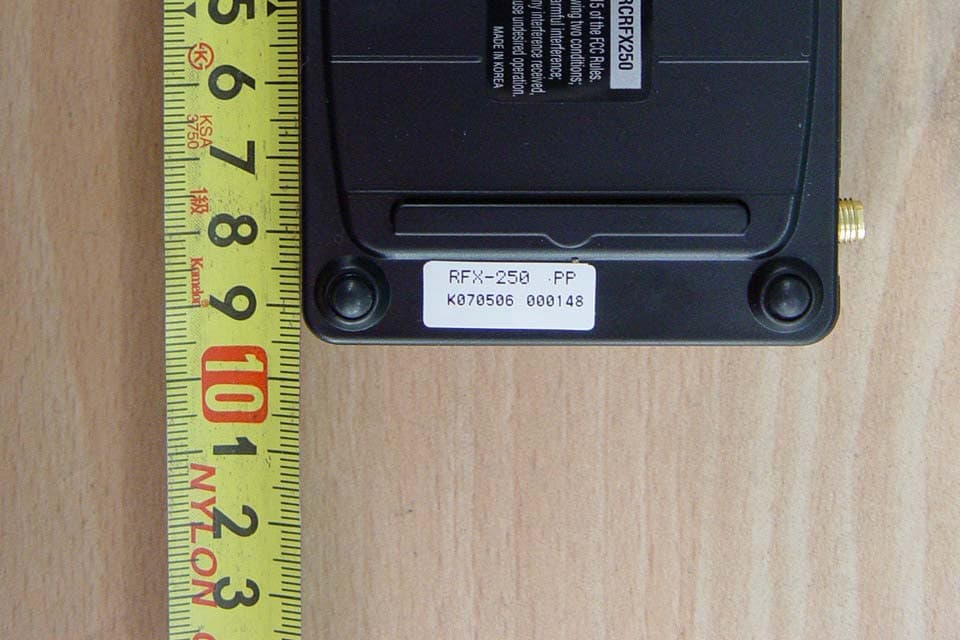
Click to zoom
Application Details
- Equipment Class
- CYY - Communications Receiver used w/Pt 15 Transmitter
- Date of Grant
- Aug 09, 2006
- Application Purpose
- Original Equipment
- Date of Application
- Aug 09, 2006
- Equipment Note
- REMOTE CONTROL RECEIVER
- Frequency Range
- 417.50000000 - 418.50000000
- Company
- Ohsung Electronics Co., Ltd.
- Country
- South Korea
Documents & Files
Document Text
Text extracted from the exhibit documents filed with the FCC. Open a document above to read the original.
Users Manual
EUT Type: Remote Control Receiver FCC ID.: OZ5URCRFX250 Test Report No.: GETEC-E3-06-058 FCC Part 15 Subpart B APPENDIX H : USER’S MANUAL 500 Mamaroneck Avenue, Harrison, NY 10528 Phone: (914) 835-4484 Fax: (914) 835-4532 www .uni v ersalremote.com COMPLETE ™ Universal Remote Control ® CONTROL COMPLETE This equipment has been tested and found to comply with the lim-its for a Class B digital device, pursuant to part 15 of the FCCRules. These limits are designed to provide reasonable protectionagainst harmful interference in a residential installation. This equip-ment generates, uses and can radiate radio frequency energy and,if not installed and used in accordance with the instructions, maycause harmful interference to radio communications.However, there is no guarantee that interference will not occur in aparticular installation. If this equipment does cause harmful inter-ference to radio or television reception, which can be determinedby turning the equipment off and on, the user is encouraged to tryto correct the interference by one more of the following measures: Reorient or relocate the receiving antenna. Increase the separation between the equipment and receiv-er. Connect the equipment into an outlet on a circuit differentfrom that to which the receiver is connected. Consult the dealer or an experienced radio/TV technicianfor help. Warning Changes or modifications not expressly approved by the manufacturercould void the user's authority to operate the equipment.Note : The manufacturer is not responsible for any Radio or TV inter-ference caused by unauthorized modifications to this equipment.Such modifications could void the user's authority to operate theequipment. Information To The User RFX-250 Installation Manual Optimizing Narrow Band Reception with the MRF-300 or MSC-400 COMPLETE ™ Universal Remote Control ® CONTROL COMPLETE Page 2 RFX-250 I NSTALLATION M ANUAL Page 1 RFX-250 I NSTALLATION M ANUAL Overview - CompatibilityThe RFX-250 is a narrow band RF receiver. It replaces an RFX-150 receiv-er in either an MRF-300 or MSC-400 system. It is tuned to receive a muchnarrower band and is more immune to the interference found near com-ponent racks (generated by microprocessors and power supplies). It isNOT compatible with all URC remote controls.Connections Optimizing Range and Reliability1. Power on all AV components, dim all dimmers to 50% and power on anything that may create RF (particularly devices with high speedmicroprocessors or hard drives). Observe the RF LED of the RFX-250 bycupping your hand over it. If it is glowing or flickering you must relo-cate the RFX-250. If you cannot relocate the RFX-250,try removing its antenna. 2. Once you have found a location that is absolutely clean with everything on, test to see if the range is adequateand that macro reliability is perfect. Start with theantenna angle set to 45 degrees and positioned so thatthe long side of the antenna is facing the customer’sfavorite seating position. 3. When testing, set both the remote and the MRF/MSC to the same VALID RFID#. Keep in mind that zero (0) is not a v alid RFID# . Watch the STATUS LED on MRF/MSC - it should light every time you press abutton on the remote. This will tell you that the signal was receivedand understood. Ignore the RF LED on the RFX-250 (it only indicatesthat a signal was received, not that it was understood). 4. If the range is inadequate, you may extend wire to any area that is not giving good results and place an additional RFX-250 in that area. Up tothree RFX-250’s can be connected to each MRF/MSC. NOTE: The RFX-250 is ONLY compatible with the current versions of the MX-3000, MX-950, MX-900 and the TX-1000 remote controls. The RFX-250 is NOT compatible with MX-3000 remote controls manufacturedbefore April 1, 2005.You can identify the build date of an MX-3000 by looking at the serialnumber. The first 6 digits indicate the build date. If the serial numberappears as 122905 014054, the first 6 digits indicate that the remote wasbuilt on December 29, 2005. NOTE: The RFX-250 is ONLY compatible with additional RFX-250s. You cannot mix RFX-150s in a system with RFX-250s. When the RFX-250 can be placed within 10 feetof the MRF/MSC unit, you can utilize the cablewith 3.5 mm plugs on both ends. When youneed a longer wire or are connecting up tothree RFX-250’s, use a cable with a minimum ofthree conductors. If you use CAT 5, utilize twoconductors each from two of the twisted pairsfor DATA and two from the other twisted pairsfor 5V. Use all four of the other conductorstwisted in with each pair for GND.This providesbetter shielding and conductivity for long runs. Connect ONE (only)of either of the RFX-250’s RF OUT connec-tors to ONE (only) ofeither of the RF INconnectors on theMRF or the MSC. Once the RFX-250 is correctly connect-ed, the POWER LED lights. If the RF LED lights, the RFX-250 mustbe moved to a new mounting location. Itis receiving in-band RF INTERFERENCE. Suggested antennaangle.
Attestation Statements
EUT Type: Remote Control Receiver FCC ID.: OZ5URCRFX250 Test Report No.: GETEC-E3-06-058 FCC Part 15 Subpart B APPENDIX A : ATTESTATION STATEMENT April 01, 2006 Federal Communications Commission Authorization and Evaluation Division Equipment Authorization Branch 7435 Oakland Mills Road Columbia, MD 21046 U.S.A To whom it may concern: We, the undersigned, hereby authorize GUMI College EMC Center to act on our behalf in all matters relating to applications for equipment authorization, including the signing of all documents relation to these matters. Any and all acts carried out by GUMI College EMC Center on our behalf shall have the same effect as acts of our own. We also hereby certify that no party to the application is subject of a denial of benefits, including FCC benefits, pursuant 5301 of the Anti-Drug Abuse Act of 1988, 21 U.S.C. 853(a). Sincerely, Kwang-jae Ok, Manager OHSUNG Electronics Co., Ltd.
Block Diagram
EUT Type: Remote Control Receiver FCC ID.: OZ5URCRFX250 Test Report No.: GETEC-E3-06-058 FCC Part 15 Subpart B APPENDIX C : BLOCK DIAGRAM EUT Type: Remote Control Receiver FCC ID.: OZ5URCRFX250 Test Report No.: GETEC-E3-06-058 FCC Part 15 Subpart B LABELLING REQUIREMENTS The label shown shall be permanently affixed at a conspicuous location on the device and be readily visible to the user at the time of purchase. ID Label ID Label Location of EUT I.D Label
Cover Letter(s)
Rev. 1/1/03 OHSUNG ELECTRONICS CO., LTD #181 Gongdan-Dong, Gumi-Si, Gyeongsangbuk-Do, Korea Tel: +82-54-468-7282, Fax: +82-54-461-8368 Federal Communications Commission Authorization and Evaluation Division Confidentiality Request regarding application for certification of FCC ID: OZ5URCRFX250 Pursuant to Sections 0.457 and 0.459 of the Commission’s Rules, we hereby request confidential treatment of information accompanying this application as outlined below: z Appendix D : Schematic Diagram z Appendix I : Operational Description The above materials contain trade secrets and proprietary information not customarily released to the public. The public disclosure of these materials may be harmful to the applicant and provide unjustified benefits to its competitors. The applicant understands that pursuant to Section 0.457 of the Rules, disclosure of this application and all accompanying documentation will not be made before the date of the Grant for this application. Sincerely, --------------------------------------------- Kwang-Jae Ok, Q.C Manager OHSUNG ELECTRONICS CO.,LTD
External Photos
EUT Type: Remote Control Receiver FCC ID.: OZ5URCRFX250 Test Report No.: GETEC-E3-06-058 FCC Part 15 Subpart B APPENDIX F : EXTERNAL PHOTOGRAPHS EUT Type: Remote Control Receiver FCC ID.: OZ5URCRFX250 Test Report No.: GETEC-E3-06-058 FCC Part 15 Subpart B EUT Type: Remote Control Receiver FCC ID.: OZ5URCRFX250 Test Report No.: GETEC-E3-06-058 FCC Part 15 Subpart B
ID Label/Location Info
EUT Type: Remote Control Receiver FCC ID.: OZ5URCRFX250 Test Report No.: GETEC-E3-06-058 FCC Part 15 Subpart B APPENDIX B : ID SAMPLE LABEL & LOCATION EUT Type: Remote Control Receiver FCC ID.: OZ5URCRFX250 Test Report No.: GETEC-E3-06-058 FCC Part 15 Subpart B LABELLING REQUIREMENTS The label shown shall be permanently affixed at a conspicuous location on the device and be readily visible to the user at the time of purchase. ID Label ID Label Location of EUT I.D Label
Internal Photos
EUT Type: Remote Control Receiver FCC ID.: OZ5URCRFX250 Test Report No.: GETEC-E3-06-058 FCC Part 15 Subpart B APPENDIX G : INTERNAL PHOTOGRAPHS EUT Type: Remote Control Receiver FCC ID.: OZ5URCRFX250 Test Report No.: GETEC-E3-06-058 FCC Part 15 Subpart B EUT Type: Remote Control Receiver FCC ID.: OZ5URCRFX250 Test Report No.: GETEC-E3-06-058 FCC Part 15 Subpart B EUT Type: Remote Control Receiver FCC ID.: OZ5URCRFX250 Test Report No.: GETEC-E3-06-058 FCC Part 15 Subpart B EUT Type: Remote Control Receiver FCC ID.: OZ5URCRFX250 Test Report No.: GETEC-E3-06-058 FCC Part 15 Subpart B EUT Type: Remote Control Receiver FCC ID.: OZ5URCRFX250 Test Report No.: GETEC-E3-06-058 FCC Part 15 Subpart B
Test Report
EUT Type: Remote Control Receiver FCC ID.: OZ5URCRFX250 Page 2 of 14 Test Report No.: GETEC-E3-06-058 FCC Part 15 Subpart B CONTENTS 1. GENERAL INFORMATION ......................................................................................................................................3 2. INTRODUCTION ........................................................................................................................................................4 3. PRODUCT INFORMATION ......................................................................................................................................5 3.1 DESCRIPTION OF EUT..............................................................................................................................................5 3.2 SUPPORT EQUIPMENT / CABLES USED.....................................................................................................................6 3.3 MODIFICATION ITEM(S)...........................................................................................................................................6 4. DESCRIPTION OF TESTS.........................................................................................................................................7 4.1 TEST CONDITION......................................................................................................................................................7 4.2 RADIATED EMISSION................................................................................................................................................8 4.3 CONDUCTED EMISSION............................................................................................................................................9 5. RADIATED EMISSION ............................................................................................................................................10 5.1 OPERATING ENVIRONMENT...................................................................................................................................10 5.2 TEST SET-UP............................................................................................................................................................10 5.3 MEASUREMENT UNCERTAINTY..............................................................................................................................10 5.4 LIMIT...................................................................................................................................................................... 11 5.5 TEST EQUIPMENT USED.......................................................................................................................................... 11 5.6 RADIATED EMISSION TEST DATA............................................................................................................................12 6. SAMPLE CALCULATIONS.....................................................................................................................................13 6.1 EXAMPLE 1 :...........................................................................................................................................................13 6.2 EXAMPLE 2 :...........................................................................................................................................................13 7. RECOMMENDATION & CONCLUSION..............................................................................................................14 APPENDIX A – ATTESTATION STATEMENT APPENDIX B – ID SAMPLE LABEL & LOCATION APPENDIX C – BLOCK DIAGRAM APPENDIX D – SCHEMATIC DIAGRAM APPENDIX E – TEST SET UP PHOTOGRAPHS APPENDIX F – EXTERNAL PHOTOGRAPHS APPENDIX G – INTERNAL PHOTOGRAPHS APPENDIX H – USER’S MANUAL APPENDIX I – OPERATIONAL DESCRIPTIO N EUT Type: Remote Control Receiver FCC ID.: OZ5URCRFX250 Page 3 of 14 Test Report No.: GETEC-E3-06-058 FCC Part 15 Subpart B Scope: Measurement and determination of electromagnetic emissions (EME) of radio frequency devices including intentional and / or unintentional radiators for compliance with technical rules and regulations of the Federal Communications Commission. 1. General Information z FCC ID. OZ5URCRFX250 z Equipment Class Communications Receiver used with Part 15 Transmitter (CYY) z EUT Type Remote Control Receiver z Power Source DC 5V z Model No. RFX-250 z Rule Part(s) FCC Part 15, Subpart B z Type of Authority Certification z Test Procedure(s) ANSI C63.4 (2003) z Dates of Test July 27, 2006 z Place of Test Gumi College EMC Center ( FCC Registration No.: 100749) 407, Bugok-Dong, Gumi-si, Gyeongsangbuk-Do, Korea z Test Report No. GETEC-E3-06-058 z Dates of Issue August 9, 2006 Applicant: OHSUNG ELECTRONICS CO., LTD. Applicant Address: #181 Gongdan-Dong, Gumi-Si, Gyeongsangbuk-do, Korea Manufacturer: OHSUNG ELECTRONICS CO., LTD Manufacturer Address: #181 Gongdan-Dong, Gumi-Si, Gyeongsangbuk-do, Korea Contact Person: Mr. Kwang-Jae Ok / Team Leader Q.C Tel. & Fax No.: Tel No.: +82-54-468- 0831 Fax No.: +82-54- 461- 8368 EUT Type: Remote Control Receiver FCC ID.: OZ5URCRFX250 Page 4 of 14 Test Report No.: GETEC-E3-06-058 FCC Part 15 Subpart B 2. Introduction The measurement procedure described in American National Standard for Methods of Measurement of Radio-Nose Emissions From Low-Voltage Electrical and Electronic Equipment in the Range of 9kHz to 40GHz (ASNI C63.4- 2003) was used in determining radiated and conducted emissions emanating from OHSUNG ELECTRONICS CO., LTD. Remote Control Receiver (Model No.: RFX-250) These measurement tests were conducted at Gumi College EMC Center. The site address is 407, Bugok-Dong, Gumi-si, Gyeongsangbuk-Do, Korea This test site is one of the highest point of Gumi 1 college at about 200 kilometers away from Seoul city and 40 kilometers away from Daege city. It is located in the valley surrounded by mountains in all directions where ambient radio s…
Text truncated - open the document above for the full version.
Test Setup Photos
EUT Type: Remote Control Receiver FCC ID.: OZ5URCRFX250 Test Report No.: GETEC-E3-06-058 FCC Part 15 Subpart B APPENDIX E : TEST SET UP PHOTOGRAPHS EUT Type: Remote Control Receiver FCC ID.: OZ5URCRFX250 Test Report No.: GETEC-E3-06-058 FCC Part 15 Subpart B Radiated Test Picture (Front) Radiated Test Picture (Rear)
Contact Information
Applicant
Hak-Ki Kim(General Manager)
Test Firm
GUMI UNIVERSITY EMC CENTERTea-Sig Park
Technical Specifications
| # | Rule Parts | Frequency Range | Power Output |
|---|---|---|---|
| 1 | 15B | 417.5 MHz - 418.5 MHz | - |
Other Applications from Ohsung Electronics Co., Ltd.
OZ5PSRMT
Jan 13, 2026RF4CE RCU
Equipment Class
DTS - Digital Transmission SystemOZ5G32
Dec 29, 2025Remote Controller
Equipment Class
DTS - Digital Transmission SystemOZ5PSEMR
Dec 19, 2025RF Module
Equipment Class
DTS - Digital Transmission SystemOZ5G22
Dec 16, 2025Remote Controller
Equipment Class
DTS - Digital Transmission SystemOZ5G12
Dec 16, 2025Remote Controller
Equipment Class
DTS - Digital Transmission System